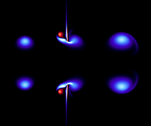



1. Introduction
The collision of a vortex ring with a surface is a dynamically rich canonical flow that has been used in a variety of vortex dynamics investigations. Walker et al. (Reference Walker, Smith, Cerra and Doligalski1987) examined a vortex ring impinging normally on a flat wall as a controlled laboratory experiment to investigate the bursting mechanism of turbulent boundary layers, wherein eruptions transfer near-wall vorticity to the outer layer. They found that the boundary layer, induced by the approaching ring, separates at the outer extent of the colliding vortex ring due to the resulting adverse pressure gradient. The separated shear layer rolls into a secondary ring, which couples with the colliding ring to rebound away from the wall, moving the boundary layer vorticity into the outer flow. By analogy, Walker et al. (Reference Walker, Smith, Cerra and Doligalski1987) proposed the sequence of unsteady separation and vortex rebound as a plausible physical mechanism behind turbulent boundary layer bursting phenomena. Swearingen, Crouch & Handler (Reference Swearingen, Crouch and Handler1995) performed spectral simulations and stability analysis on the vortex ring–wall interaction. They determined that the secondary vortex ring ejected from the boundary layer is unstable under the strain field of the primary vortex ring, which leads to turbulent transition. Verzicco & Orlandi (Reference Verzicco and Orlandi1994) examined the collision of a vortex ring with an inclined flat wall to investigate the role of differential stretching, finding that a high-pressure region forms in the leeward side of the ring due to high strain from stretching, which creates a pressure gradient that drives vorticity to the windward side. Recently, New et al. (Reference New, Long, Zang and Shi2020) investigated the head-on collision of a vortex ring with a V-wall, and observed that the additional constraints imposed by the V-wall introduces a complex three-dimensional vortex dynamics in comparison to a single inclined plane. New & Zang (Reference New and Zang2017) examined the head-on collision of a vortex ring with a cylinder to elucidate the vortex dynamics near arbitrarily contoured boundaries, noting that the strong interactions between the primary and secondary vortex rings due to the curvature lead to the ejection of smaller ringlets. In addition to the aforementioned studies with solid boundaries, vortex interactions with other interfaces, including free surfaces (Archer, Thomas & Coleman Reference Archer, Thomas and Coleman2010), granular surfaces (Masuda et al. Reference Masuda, Yoshida, Ito, Furuya and Sano2012), porous surfaces (Naaktgeboren, Krueger & Lage Reference Naaktgeboren, Krueger and Lage2012; Xu et al. Reference Xu, Wang, Feng, He and Wang2018) and stratified interfaces (Olsthoorn & Dalziel Reference Olsthoorn and Dalziel2017, Reference Olsthoorn and Dalziel2018) have been explored.
The dynamics of a vortex impacting the edge of a finite length plate are further complicated by vorticity generated and shed from the plate tip. Potential flow analysis of point vortices interacting with a finite length plate predicts very high (singular) bounded vorticity at the plate tip, which sharply influences local vortex trajectories (Alben Reference Alben2012; Peterson & Porfiri Reference Peterson and Porfiri2012b; Nitsche Reference Nitsche2017). Peterson & Porfiri (Reference Peterson and Porfiri2013) examined a vortex dipole colliding with a thin semi-infinite plate in a viscous fluid, wherein the dipole axis of symmetry aligned directly with the plate tip. They found in this configuration that the dipole splits in two upon impact with the plate, with the two dipole halves then coupling with secondary boundary layer vorticity and vorticity shed from the plate tip to form two new secondary dipoles that followed curved trajectories away from the plate. Zivkov et al. (Reference Zivkov, Yarusevych, Porfiri and Peterson2015) replaced the semi-infinite plate with a flexible plate and detailed the resulting changes in shed vorticity, which impacted the secondary dipole trajectories. In these studies, the vortex cores remained relatively undisturbed during the plate interaction by virtue of the initial vortex/plate alignment. The dynamics of a direct collision of a viscous vortex core with a thin plate edge, however, remains relatively unexplored. Hu & Peterson (Reference Hu and Peterson2018) experimentally studied a vortex ring colliding with a co-axial aperture to explore the dynamics of a viscous vortex core impacting a thin edge. The degree of core impact with the thin edge was controlled by the aperture-to-ring radius ratio, and the axisymmetry of the geometry enforced in a largely two-dimensional interaction. Their investigation explored a range of aperture-to-ring radius ratios and revealed that a vortex ring exited the aperture regardless of aperture size. For small radius ratios, the wall blocked the majority of the incoming ring, which subsequently followed the classical vortex rebound trajectory. The colliding ring did, however, induce flow through the aperture, which created a shear layer from the tip that formed into a new vortex ring exiting the aperture. For sufficiently large apertures, vortex rebound no longer occurred and the entire incoming ring passed through the aperture. Interestingly, they detected a rise in the hydrodynamic impulse for radius ratios of the order of one, although the physical mechanism for this was not investigated.
In this paper we seek to elucidate the physical mechanisms associated with the experimentally observed vortex impulse enhancement detailed by Hu & Peterson (Reference Hu and Peterson2018). In essence, this is an exploration of the dynamics of a vortex core interacting with a plate tip. While of fundamental interest, this has potential practical engineering applications in the development of energy harvesting devices that transduce vortex-induced structural deformations into electrical energy (Peterson & Porfiri Reference Peterson and Porfiri2012a; Hu et al. Reference Hu, Cha, Porfiri and Peterson2014). The paper is organized as follows: § 2 outlines the problem formulation and numerical set-up; § 3 provides an overview of the vortex dynamics; § 4 examines the passive enhancement of hydrodynamic impulse experienced by the incoming vortex ring; § 5 explains the structural loading experienced from the core interaction; § 6 discusses the circulation changes of the vortex ring after the interaction; § 7 briefly touches upon the influence of Reynolds number; and § 8 summarizes the major findings of the work.
2. Problem definition
We numerically explore the problem of an axisymmetric vortex ring colliding with a wall with a co-axial aperture of radius  $R_a$ in an otherwise quiescent viscous fluid, as shown schematically in figure 1. A cylindrical coordinate system (
 $r$,
 $x$) with origin at the centre of the aperture is defined such that the
 $x$ direction aligns with the aperture axis and is positive in the direction of the incoming vortex ring propagation. The velocity field is given by
 $\boldsymbol {u} = (u_x,u_r)$, where
 $u_x$ and
 $u_r$ are the axial and radial components, respectively. The azimuthal vorticity field is obtained from
 $\omega _\theta (x,r,t) = \partial u_r/\partial x - \partial u_x/\partial r$, while the vortex ring circulation is computed as
 \begin{equation} \varGamma(t) = \iint_\varOmega \omega_\theta (x,r,t) \, \mathrm{d} x\, \mathrm{d} r, \end{equation}
where  $\varOmega$ is the vortex core region, defined herein by the contour of
 $1\,\%$ of the initial maximum vorticity of the ring (
 $0.01\max [\omega _\theta (x,r,0)]$). The vortex ring radius is given by
 $R(t)$, which we define as the distance from the
 $x$-axis to the location of maximum vorticity within the vortex core. The vortex ring radius is located with sub-grid scale accuracy by fitting a Gaussian distribution to the vorticity field in the least squares sense, similar to sub-pixel interpolation schemes for correlation peak detection in particle image velocimetry (Raffel et al. Reference Raffel, Willert, Wereley and Kompenhans2007). The volumetric flow rate through the aperture is computed as
 \begin{equation} Q(t) = \int_0^{R_a} u_x(r,0,t)\, r \, \mathrm{d} r \end{equation}
and the pressure difference across the wall is given by  $\Delta p(r,t)$.
Schematic of a vortex ring interacting with a rigid wall with a co-axial aperture in an otherwise quiescent fluid.

The primary interest of this article is to examine how the momentum of the impinging ring is altered by its interaction with the aperture. Thus, it is convenient to express the momentum of the flow field in terms of vorticity. Applying the derivative moment transformation to the density normalized momentum integral yields
 \begin{equation} \int_{C_v} \boldsymbol{u}\, \mathrm{d} V = \tfrac{1}{2}\int_{C_v} \boldsymbol{x}\times\boldsymbol{\omega}\, \mathrm{d}V - \tfrac{1}{2} \int_{\partial{C_v}}\boldsymbol{x}\times(\boldsymbol{n}\times\boldsymbol{u})\, \mathrm{d}S, \end{equation}
where  $\boldsymbol {x}$ and
 $\boldsymbol {n}$ are position and boundary normal unit vectors (Wu, Ma & Zhou Reference Wu, Ma and Zhou2015), and
 $\partial C_v$ is the boundary of the control volume
 $C_v$. dV and dS are the differential volume and differential surface, respectively. The first term on the right-hand side of (2.3) is the hydrodynamic impulse (or vortex impulse), while the second term accounts for boundary flux and motions. Assuming the fluid in the far field is quiescent, and no slip along the wall, the second term is zero (Allen, Jouanne & Shashikanth Reference Allen, Jouanne and Shashikanth2007; Wu et al. Reference Wu, Ma and Zhou2015). Further assuming axisymmetry, the hydrodynamic impulse
 $I(t)$ simplifies to
 \begin{equation} I(t) = {\rm \pi}\iint_{C_v} \omega_\theta(x,r,t)\, r^2\, \mathrm{d} x\, \mathrm{d} r. \end{equation}
By integrating over the vortex core  $\varOmega$, (2.4) can be used to compute hydrodynamic impulse of a vortex ring (Saffman Reference Saffman1993; Gharib, Rambod & Shariff Reference Gharib, Rambod and Shariff1998). As note by Cantwell (Reference Cantwell1986) for an unbounded fluid,
 $I(t)$ only accounts for
 $2/3$ of the external forcing required to generate the fluid momentum, with the remainder needed to adjust the far-field pressure to oppose the motion.
Aperture to initial ring radius ratios ( $R_a/R_i$) spanning from
 $0$ to infinity (
 $R_a/R_i = 0$,
 $0.2$,
 $0.4$,
 $0.6$,
 $0.8$,
 $0.9$,
 $1.0$,
 $1.1$,
 $1.2$,
 $1.3$,
 $1.4$,
 $1.6$,
 $1.8$ and
 $\infty$) at three Reynolds numbers (
 $Re = \varGamma _i/\nu = 1000$, 2000 and 3000) are considered, where
 $\nu$ is the fluid kinematic viscosity. The subscript
 $i$ denotes the initial properties of the vortex ring (
 $t=0$), when the vortex ring is located
 $4R_i$ upstream of the aperture. For the purpose of comparison, the final properties of the vortex ring, denoted by subscript
 $f$, are taken when the vortex ring completely clears the aperture. The final times are
 $t_f\varGamma _i/R_i^2 = 42.3$,
 $39.1$ and
 $38.0$ for
 $Re=1000$,
 $2000$ and
 $3000$, respectively, where
 $t$ is time.
2.1. Numerical set-up
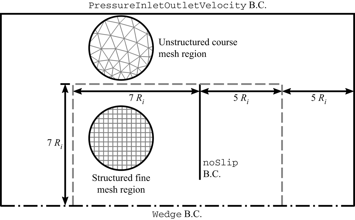
The two-dimensional axisymmetric simulations were performed using the second-order accurate transient incompressible Naiver–Stokes equations solver icoFoam in OpenFOAM 4.1. The wedge-shaped computational domain, comprising fine and course mesh regions generated using Gmsh (Geuzaine & Remacle Reference Geuzaine and Remacle2009), is summarized in figure 2. All vortex interactions occur in the  $12R_i \times 7R_i$ fine mesh region, which comprises
 $0.01R_i \times 0.01R_i$ structured cuboid elements. A course triangular prism mesh pads the fine mesh region, extending the domain by an additional
 $5R_i$ in all directions (except for the axisymmetry boundary) to reduce the influence of the far-field boundary condition. The employed numerical scheme is not energy conserving (Orlandi Reference Orlandi1990; Peterson & Porfiri Reference Peterson and Porfiri2013), and, as such, the mesh size used in this study is much smaller than previous second-order accurate vortex ring–wall interaction simulations (e.g. Chu, Wang & Chang Reference Chu, Wang and Chang1995a) to minimize numerical diffusion effects (Peterson & Porfiri Reference Peterson and Porfiri2013). The mesh size is sufficiently small that the boundary layer near the aperture plate is resolved without mesh inflation layers. The mesh size was selected based on a grid convergence study of the full wall impact (
 $R_a/R_i=0$) case, which produces the most vorticity and strongest boundary layer. The convergence metric was peak enstrophy varying by less than
 $1\,\%$.
Schematic of the computational domain. Note: B.C. stands for boundary condition.

The vortex core radius is assumed to be much larger than the plate thickness, and thus the wall is modelled with a zero thickness no-slip baffle extending to the edge of the fine mesh region. Note that the wall does not extend to the outer unstructured region to prevent back pressure across the aperture, similar to the experiments of Hu & Peterson (Reference Hu and Peterson2018). The totalPressure is applied as the far-field boundary condition, which sets the pressure  $p=0$ for outflow and
 $p=|\boldsymbol {u}|^2/2$ for inflow to mimic an unbounded fluid domain. The wedge boundary condition is applied on the faces of the one-element-thick domain to facilitate the axisymmetric simulation.
2.2. Vortex initialization
The vortex ring was initialized in an open domain (no wall) with a Gaussian (Lamb–Oseen) vorticity distribution given by
 \begin{equation} \frac{\omega_\theta(x,r,0) R_o^2}{\varGamma_o} = \frac{1}{{\rm \pi} (R_c/R_o)^2} \exp\left[ -\frac{(x-x_o)^2/R_0^2 + (r-R_o)^2/R_o^2}{(R_c/R_o)^2} \right], \end{equation}
where  $\varGamma _o$,
 $R_c$,
 $R_o$ and
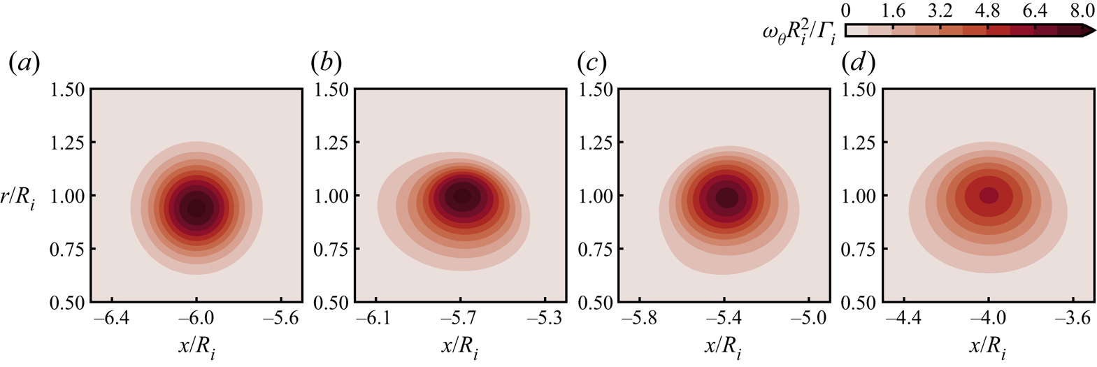
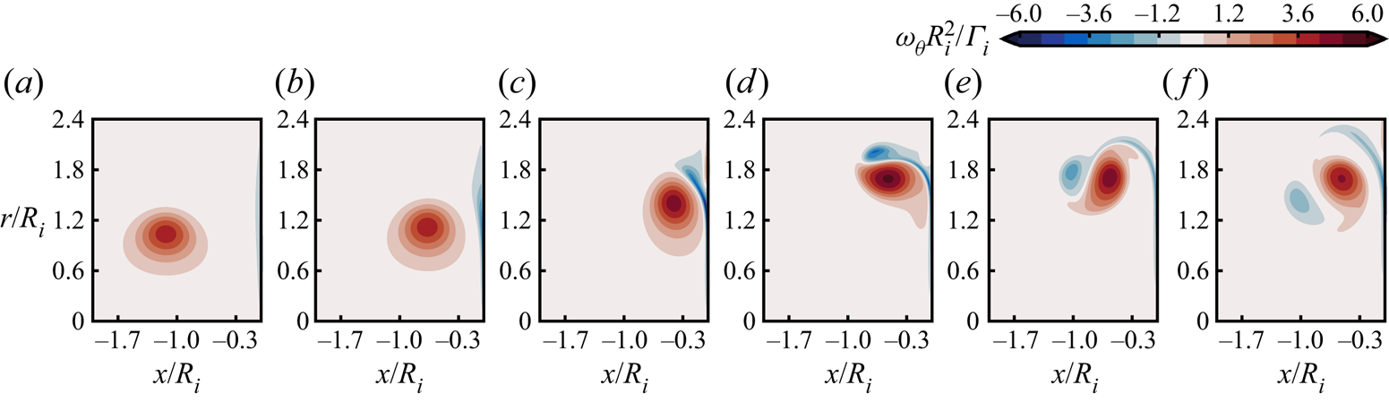
 $x_o$ are the circulation, core radius, ring radius and axial position of the ring, respectively. The simulation was allowed to evolve until the vortex core obtained a stable vorticity distribution, as shown in figure 3. This vorticity distribution was then mapped to the actual domain (with wall and aperture) with the ring centred at
 $x/R_i=-4$. The values of
 $\varGamma _o$,
 $R_c$ and
 $R_o$ were selected such that the vortex ring had the desired initial attributes
 $R_i$ and
 $\varGamma _i$ after core transition completed (figure 3d).
Initial transition of the vortex core from a Gaussian distribution to a realistic elliptical distribution. Vorticity fields are shown at  $tR_i^2/\varGamma _i \approx$ (a)
 $-8.3$, (b)
 $-7.2$, (c)
 $-5.9$ and (d)
 $0$ for all Reynolds numbers.

2.3. Validation
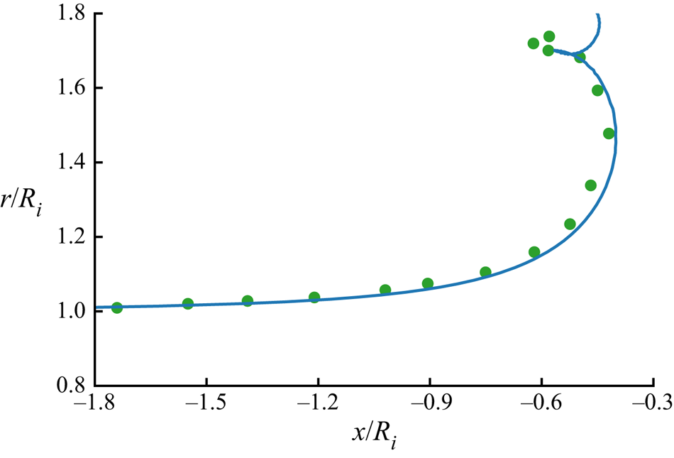
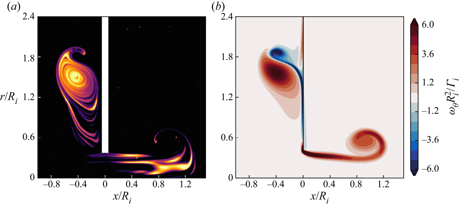
We validate the simulations by comparison with published experimental data for two conditions: a vortex ring impacting a solid wall (Chu et al. Reference Chu, Wang and Chang1995a); and a vortex ring interacting with a co-axial aperture (Hu & Peterson Reference Hu and Peterson2018). Figure 4 compares the trajectories of a vortex ring impacting a solid wall from the simulations and experiments for  $Re=2000$. The simulation accurately predicts the vortex rebound observed experimentally using flow visualization. This further implies that the vortex position in simulations can be assessed with reasonable accuracy via the vorticity peak location, despite the core deformation during the collision. Qualitative comparison with flow visualizations of a vortex ring interacting with a co-axial aperture (Hu & Peterson Reference Hu and Peterson2018) are shown in figure 5 for
 $R_a/R_i = 0.4$ at
 $Re = 4000$ (figure 16 in § 4.1 further compares experiment and simulation results for the
 $R_a/R_i = 1.2$ case). The simulations show very good agreement with the experiments, accurately capturing the core deformation and secondary vortex production throughout the interaction.
Trajectory of a vortex ring impacting a wall at  $Re=2000$. Simulation results are represented by a line, while the experimental results from Chu et al. (Reference Chu, Wang and Chang1995a) are marked by dots.

Comparison between (a) flow visualization (Hu & Peterson Reference Hu and Peterson2018) and (b) simulation of a vortex ring impacting a coaxial aperture with  $R_a/R_i = 0.4$ and
 $Re = 4000$.

Of potential concern is the impact of the employed axisymmetric assumption on the flow development. Orlandi & Verzicco (Reference Orlandi and Verzicco1993), for example, have shown that the axisymmetric condition prevents azimuthal instability development at higher Reynolds numbers. However, Swearingen et al. (Reference Swearingen, Crouch and Handler1995) revealed that the azimuthal instability develops on the secondary vortex ring under the strain field of the primary vortex ring. Hu & Peterson (Reference Hu and Peterson2018) have shown the strength of both the primary and secondary vortex rings are reduced due to the aperture, which damps the azimuthal instability. Furthermore, the azimuthal instability only reaches a noticeable amplitude at the late stage of the interaction for the classical vortex ring–wall interaction case (Orlandi & Verzicco Reference Orlandi and Verzicco1993; Swearingen et al. Reference Swearingen, Crouch and Handler1995; Cheng, Lou & Luo Reference Cheng, Lou and Luo2010). Thus, the occurrence of the azimuthal instability far exceeds the timescale of interest in the present study, and the axisymmetric simulations are deemed adequate for the Reynolds numbers investigated. This is corroborated by the observation that the dye layers in the flow visualization of Hu & Peterson (Reference Hu and Peterson2018) (see figure 5a) are preserved upon impact, indicating that the flow remains laminar throughout the interaction.
3. Results overview
We classify the vortex dynamics of the ring–aperture interaction into three regimes depending on the aperture to initial ring radius ratio  $R_a/R_i$, namely, the impact, ‘vortex nozzle’ and slip-through regimes. For the impact regime (
 $R_a/R_i \lessapprox 0.9$), the aperture wall blocks most of the colliding vortex ring and causes it to rebound, with behaviour qualitatively similar to a vortex ring impacting a solid wall. In the slip-through regime (
 $R_a/Ri \gtrapprox 1.3$) the majority of the incoming ring passes through the aperture and no rebound is observed. The ‘vortex nozzle’ regime (
 $0.9 \lessapprox R_a/R_i \lessapprox 1.3$) exhibits behaviour qualitatively similar to the slip-through regime, however, quantitatively, the vortex ring impulse is enhanced during the interaction with the aperture. These three regimes are discussed in the following sub-sections using the
 $Re = 2000$ case as an exemplar.
3.1. Impact regime
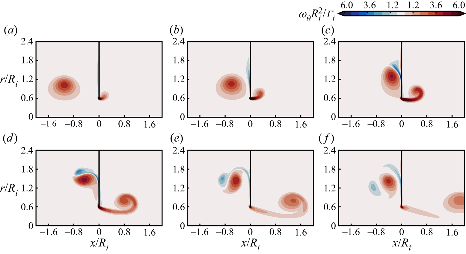
We begin with the special case of a vortex ring impacting a solid wall ( $R_a/R_i = 0.0$) as a reference baseline; the vorticity evolution is shown in figure 6. This configuration is well documented, see, for example, Walker et al. (Reference Walker, Smith, Cerra and Doligalski1987) and Cheng et al. (Reference Cheng, Lou and Luo2010), and as such we include only a brief description herein. In figure 6(a,b), a boundary layer is induced as the vortex ring approaches the wall. Upon collision in figure 6(c,d), the lower-pressure vortex core imposes an adverse pressure gradient that leads to unsteady boundary layer separation. The separated boundary layer rolls into a secondary ring, which couples with the impinging ring and rebounds, as shown in figure 6(d–f).
Vorticity evolution for  $R_a/R_i = 0.0$ at
 $Re = 2000$, with an increase in time from (a)
 $t\varGamma _i/R_i^2 \approx 13.0$ to (f)
 $t\varGamma _i/R_i^2 \approx 25.9$ at an interval of
 $t\varGamma _i/R_i^2 \approx 2.6$.

Figure 7 displays the evolution of the  $R_a/R_i = 0.6$ case, which exhibits similar features to the
 $R_a/R_i=0$ case, including boundary layer formation and separation (figure 7a–c) and subsequent coupling with the incoming ring and rebound from the wall (figure 7d–f). However, at the aperture, same-sign vorticity forms at the aperture edge as fluid is forced through the opening as the approaches, see figure 7(a,b). The vortex-induced shear layer at the aperture tip spirals into a new vortex ring in a manner similar to vortex ring formation by a piston/cylinder generator (Gharib et al. Reference Gharib, Rambod and Shariff1998) and discussed by Hu & Peterson (Reference Hu and Peterson2018).
Vorticity evolution for  $R_a/R_i = 0.6$ at
 $Re = 2000$, with an increase in time from (a)
 $t\varGamma _i/R_i^2 \approx 13.0$ to (f)
 $t\varGamma _i/R_i^2 \approx 25.9$ at an interval of
 $t\varGamma _i/R_i^2 \approx 2.6$. Corresponding movies are available in the supplementary materials available at available at https://doi.org/10.1017/jfm.2021.294.

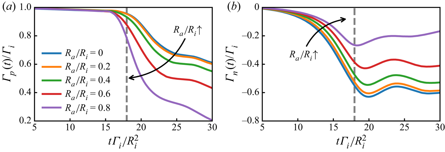
To further explore the rebound dynamics, we consider the evolution of the total positive,  $\varGamma _p$, and negative,
 $\varGamma _n$, circulations in the
 $x/R_i < 0$ half-plane in figure 8. The circulations
 $\varGamma _p$ and
 $\varGamma _n$ are computed from (2.1) with
 $\omega _\theta$ filtered to include only positive and negative-signed vorticity in the integration domain, respectively. Figure 8(a) shows the colliding vortex ring during its interaction. With no aperture (solid wall), circulation reduces through cross-diffusion with the opposite-signed vorticity generated along the wall. As the aperture ratio increases, the amount of opposite-signed vorticity generated along the wall decreases, as shown by the evolution of
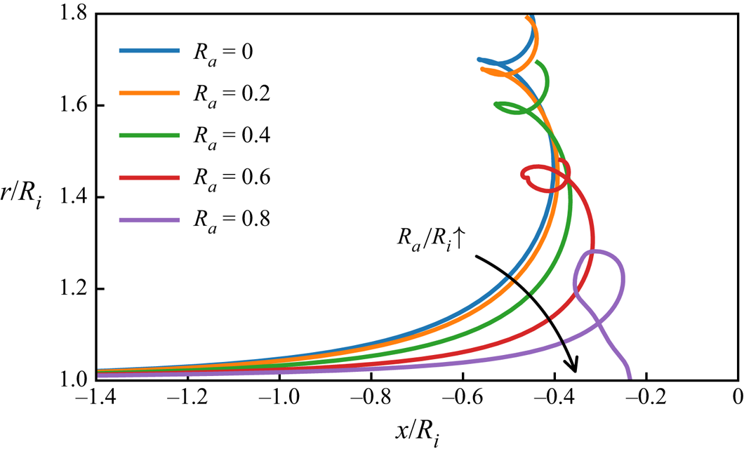
 $\varGamma _n$ in figure 8(b). Despite the reduction in opposite-signed vorticity generation, the circulation loss of the incoming ring is more pronounced as the aperture ratio increases due to the direct vorticity transport through the aperture. The directly transported vorticity joins the new ring formed by the shear layer emanating from the aperture tip. As a consequence of the reduced circulation at larger apertures ratios, the vortex rebound is weakened, as shown by the primary vortex ring trajectories in figure 9.
Circulation evolution of the (a) colliding,  $\varGamma _p(t)$, and (b) secondary,
 $\varGamma _n(t)$, vortex rings for
 $Re=2000$ throughout the interaction for
 $R_a/R_i=0.0$ to
 $0.8$. The dashed line indicates the time at which a ring would pass the
 $x/R_i=0$ plane in the absence of a wall (
 $R_a/R_i=\infty$).

Trajectory of the primary vortex ring core for radius ratios in the range  $R_a/R_i=0.0$ to
 $0.8$ at an interval of
 $0.2$ and
 $Re=2000$.

Once the radius ratio reaches  $R_a/R_i \approx 0.9$, so much of the colliding vortex ring passes through the aperture that the remaining ring is too weak to rebound, which marks the upper limit of the impact regime.
3.2. Slip-through regime
When the aperture radius is larger than the incoming vortex ring, the ring will slip through the aperture instead of rebounding, as shown by the vorticity evolution for  $R_a/R_i = 1.4$ in figure 10. The vortex ring no longer induces an appreciable boundary layer on the facing plane, as displayed in figure 10(a). The flow in the vicinity of the aperture edge due to the main ring is now in the retrograde direction, resulting in a shear layer of opposite-signed vorticity moving upstream, see figure 10(b,c). This vorticity rolls up into a new tip vortex of opposite sign to that generated in the impact regime, see figure 10(c). This newly formed tip ring is drawn downstream by the passing ring, which is in turn deformed by its presence, as illustrated in figure 10(d). Towards the end of the interaction, figure 10(e,f), the passing vortex ring reorganizes itself and propagates away from the aperture.
Vorticity evolution for  $R_a/R_i = 1.4$ at
 $Re = 2000$, with an increase in time from (a)
 $t\varGamma _i/R_i^2 \approx 13.0$ to (f)
 $t\varGamma _i/R_i^2 \approx 25.9$ at an interval of
 $t\varGamma _i/R_i^2 \approx 2.6$. Corresponding movies are available in the supplementary materials.

For cases with even larger aperture ratio, the influence of the aperture continues to diminish. The opposed-signed tip vortex ring is produced until  $R_a/R_i \approx 1.8$, but it does not interact with the passing ring to any meaningful degree for
 $R_a/R_i \gtrapprox 1.6$. Rather, the tip ring propagates upstream (in the negative
 $x$ direction), while the primary ring passes with no major disturbance. For
 $R_a/R_i \gtrapprox 1.8$, the influence of the aperture is essentially negligible.
3.3. Vortex nozzle regime
The vortex nozzle regime ( $0.9 \lessapprox R_a/R_i \lessapprox 1.3$) shares qualitative similarity with the slip-through regime in terms of the vortex dynamics, as shown in figure 11. The incoming vortex ring induces an opposite-signed boundary layer near the aperture tip (figure 11a,b), that eventually separates when the colliding vortex ring is close to the aperture (figure 11c). The secondary vortex ring does not rebound, but is rather pulled towards the aperture. The wall deforms the primary and secondary rings (figure 11d), both of which are pulled through the aperture (figure 11e). The secondary ring also induces a shear layer near the aperture edge that feeds back to the passing vortex ring. At the same time, the passing ring reorganizes its deformed core, similar to the spiralling of a vortex sheet during the formation process of a vortex ring (Didden Reference Didden1979; Heeg & Riley Reference Heeg and Riley1997; Mohseni, Ran & Colonius Reference Mohseni, Ran and Colonius2001). After the interaction, the passing vortex re-spirals its core into a Gaussian-like distribution and continues to propagate onward (figure 11f). The complex tip vortex dynamics for this aperture-to-ring size leads to interesting quantitative modifications to the passing ring, as discussed in the next section.
Vorticity evolution for  $R_a/R_i = 1.0$ at
 $Re = 2000$, with an increase in time from (a)
 $t\varGamma _i/R_i^2 \approx 13.0$ to (f)
 $t\varGamma _i/R_i^2 \approx 25.9$ at an interval of
 $t\varGamma _i/R_i^2 \approx 2.6$. Corresponding movies are available in the supplementary materials.

4. Passive enhancement of the hydrodynamic impulse
Figure 12 presents the final vortex ring impulse  $I_f = I(t \varGamma _i/R_i \approx 39.1)$ computed from (2.4) as a function of aperture-to-ring radius ratio for
 $Re=2000$. The results are normalized by the baseline impulse,
 $I_\infty$, of a vortex ring advecting through the domain in absence of a wall (
 $R_a/R_i=\infty$) at the same time point. In the impact and slip-through regimes (
 $R_a/R_i \lessapprox 0.9$ and
 $R_a/R_i \gtrapprox 1.3$, respectively), the final ring impulse is lower than that of a freely advecting ring due to losses associated with interaction with the wall and aperture tip, respectively. The normalized final impulse tends towards unity as
 $R_a/R_i$ becomes large, as expected. Interestingly, when the ring radius is approximately the same as the aperture radius, we observe impulse enhancement, which is the defining feature of the vortex nozzle regime introduced in § 3. As seen in figure 12, the vortex ring can increase its hydrodynamic impulse by more than
 $8\,\%$ compared to a freely convecting vortex ring through this nozzle effect for
 $Re=2000$, with the largest enhancement observed for
 $R_a/R_i=1.1$.
Final hydrodynamic impulse,  $I_f$, of the passing vortex ring for various radius ratios,
 $R_a/R_i$, taken at
 $t\varGamma _i/R_i^2 \approx 39.1$ for
 $Re=2000$. Radius and circulation are normalized by the baseline case of a freely advecting vortex ring (
 $R_a/R_i=\infty$) at the same time point.

To better understand the physics of the impulse enhancement, we consider Fraenkel's model of a vortex ring to express the impulse and energy (Fraenkel Reference Fraenkel1972; Sullivan et al. Reference Sullivan, Niemela, Hershberger, Bolster and Donnelly2008) given to second order by
 \begin{gather} I= {\rm \pi}\varGamma R^2\left[1 + \frac{3}{4} \left(\frac{R_c}{R}\right)^2 \right], \end{gather}
 \begin{gather}E = \frac{1}{2} \varGamma^2 R \left[ \ln\frac{8R}{R_c} - \frac{7}{4} + \frac{3}{8}\left(\frac{R_c}{R}\right)^2\ln\frac{8R}{R_c} \right]. \end{gather}
In the present simulations, the final core-to-ring radius ratio ( $R_c/R$) for the impulse enhancement cases differs by less than
 $2\,\%$ from that of a freely advecting vortex, which accounts for at most
 $0.2\,\%$ of the impulse variation and
 $1\,\%$ of the energy variation based on (4.1). Hence, we neglect the terms in square brackets in (4.1) for the remainder of this discussion and focus only on the leading-order changes due to variations in the primary variables
 $\varGamma$ and
 $R$ only.
Considering the first-order terms of (4.1), we can compare post-impact properties  $I_f$ and
 $E_f$ with analogous properties for a free ring, yielding
 \begin{gather} \frac{I_f}{I_\infty} \approx \left(\frac{\varGamma_f}{\varGamma_\infty}\right)\left(\frac{R_f}{R_\infty}\right)^2, \end{gather}
 \begin{gather}\frac{E_f}{E_\infty} \approx \left(\frac{\varGamma_f}{\varGamma_\infty}\right)^2\left(\frac{R_f}{R_\infty}\right), \end{gather}
which can be combined to give
 \begin{equation} \frac{I_f}{I_\infty} \approx \left(\frac{E_f}{E_\infty}\right)^{1/2} \left(\frac{R_f}{R_\infty}\right)^{3/2}. \end{equation}
Noting that the rigid wall does no work on the fluid, and the ring losses energy to vorticity production at the no-slip boundary during the interaction (figure 11), then  ${E_f/E_\infty < 1}$. Therefore, according to (4.3), the observed impulse enhancement (
 $I_f/I_\infty > 1$) must coincide with an increase in ring radius (
 $R_f/R_\infty > 1$). Figure 13(a) shows that indeed the final ring radius,
 $R_f$, is larger than that of a freely convecting vortex ring in the vortex nozzle regime.
Final (a) radius,  $R_f$, and (b) circulation,
 $\varGamma _f$, of the passing vortex ring for various radius ratios,
 $R_a/R_i$, taken at
 $t\varGamma _i/R_i^2 \approx 39.1$ for
 $Re=2000$. Impulse is normalized by the baseline case of a freely advecting vortex ring (
 $R_a/R_i=\infty$) at the same time point.

Furthermore, rearranging (4.2) yields
 \begin{equation} \frac{I_f}{I_\infty} \approx \left(\frac{E_f}{E_\infty}\right)^{2} \left(\frac{\varGamma_f}{\varGamma_\infty}\right)^{{-}3}, \end{equation}
revealing that the impulse enhancement must be accompanied by a decrease in circulation ratio ( $\varGamma _f/\varGamma _\infty < 1$). Figure 13(b) shows that the circulation of the vortex ring does indeed decrease through the interaction with the aperture, although the loss of circulation is somewhat mitigated in the vortex nozzle regime. The mechanisms behind this will be discussed in greater detail in § 6.
4.1. Fluid entrainment
The volume of a vortex ring can be approximated with an ellipsoid with a semi-major axis that is proportional to the ring radius (Sullivan et al. Reference Sullivan, Niemela, Hershberger, Bolster and Donnelly2008). Thus, the radial expansion of the passing vortex ring observed in figure 12(a) for the vortex nozzle regime implies that fluid entrainment occurs during the aperture interaction. That is, the mechanism of the impulse enhancement is the fluid entrainment process. To further explore the role of fluid entrainment in the impulse enhancement, we express the impulse in terms of ring volume,  $\mathcal {V}$, and velocity,
 $U$, as follows:
 \begin{equation} I(t) = (1+C_{am})\ \mathcal{V}(t)\ U(t), \end{equation}
where  $C_{am} \approx 0.72$ is the constant added mass correction (Dabiri Reference Dabiri2006; Sullivan et al. Reference Sullivan, Niemela, Hershberger, Bolster and Donnelly2008; Tinaikar, Advaith & Basu Reference Tinaikar, Advaith and Basu2018). We note that
 $C_{am}$ is purely dependent on the core to ring radius ratio, which is unaffected by the wall interaction in the vortex nozzle regime. Thus, it is reasonable to assume that
 $C_{am}$ remains constant.
The convective velocities of the ring obtained from the simulations are illustrated in figure 14(a). Except for large radius ratios,  $U_f/U_\infty < 1$, indicating that the ring loses velocity during the wall interaction, consistent with the reduction in circulation and the rise in ring radius observed in figure 13 (Fraenkel Reference Fraenkel1972; Sullivan et al. Reference Sullivan, Niemela, Hershberger, Bolster and Donnelly2008). Therefore, the only way for the ring to gain impulse is for its volume to increase. This is supported by figure 14(b), which shows a substantial increase of the passing vortex ring's volume in the vortex nozzle regime. The largest volume gain of
 $24\,\%$ occurs at
 $R_a/R_i = 1.1$, which is the radius ratio that also exhibits the largest impulse enhancement.
Final (a) velocity and (b) volume of the passing vortex ring,  $\mathcal {V}_f$, vs radius ratio,
 $R_a/R_i$, taken at
 $t_f\varGamma _i/R_i^2 \approx 39.1$ for
 $Re=2000$. Velocity and volume are normalized by the baseline case of a freely advecting vortex ring (
 $R_a/R_i=\infty$) at the same time point;
 $Re=2000$ shown.

Entrainment is visualized by seeding fluid along the front and back of the aperture wall with passive tracers at  $t\varGamma _i/R_i^2 \approx 0$, as shown in figure 15(a), and allowing them to passively advect until
 $t_f\varGamma _i/R_i^2 \approx 39.1$, with the final positions displayed in figure 15(b). Solid black dots mark tracers that are ultimately entrained into the ring. The initial position of these black tracers indicate that the fluid near the front of the aperture (
 $0.9 < r/R_i < 1.5$) is entrained into the passing vortex ring during the collision. Comparing with the vorticity distribution in figure 11, the tip vortex ring occupies the initial black tracer area during the collision, hinting at the tip vortex ring's role in the entrainment process.
Fluid tracers at their (a) initial seeding position and (b) final locations at  $t_f\varGamma _i/R_i^2 \approx 39.1$ for
 $R_a/R_i = 1.0$ and
 $Re = 2000$. Black circles indicate the tracers entrained into the vortex ring during collision.

To further explore the entrainment mechanism in relationship with the tip vortex ring, we display vorticity field snapshots and their corresponding experimental flow visualizations for  $R_a/R_i=1.2$ in figure 16. This initial vortex ring is marked with fluorescent dye in the experiments (see Hu & Peterson (Reference Hu and Peterson2018) for further details) In figure 16(a,d), region A illustrates the formation of the tip vortex ring. The lack of dye within the core of the tip ring shows that it comprises ambient fluid near the plate. In figure 16(b,e), the tip vortex begins to draw fluid away from the aperture wall and injects it towards the aperture, as shown by the arrows labelled B (see also figure 11e). Eventually, the passing vortex ring entrains the injected fluid, as shown by the fluid circled and labelled C in figure 16(c,f). Such entrainment has previously been described by Dabiri & Gharib (Reference Dabiri and Gharib2004) during formation, wherein the vortex ring captures the fluid within the vortex ring ‘bubble’. The sequence of events depicted in figure 16 reveals that the tip vortex ring is the driving agent behind the fluid entrainment that enables the impulse amplification. The coupling between the tip vortex ring and the aperture wall creates a jet that feeds ambient fluid into the passing vortex ring.
Snapshots of (a–c) vorticity field and (d–f) flow visualization of  $R_a/R_i = 1.2$ at
 $Re = 4000$. Columns correspond to
 $t\varGamma /R^2 \approx 1.80$,
 $20.2$ and
 $22.5$ from left to right.

A freely advecting vortex ring has zero net volumetric flux across a plane perpendicular to its path since it replaces the displaced volume by sweeping fluid from in front to behind the ring (Dabiri Reference Dabiri2006). In the present case, the physical obstruction of the wall results in net positive mass flux through the aperture as the travelling ring forces fluid through the hole. Mass is conserved across the plane of the wall by virtue of retrograde flow beyond the extent of the finite expanse wall. Figure 17 presents the peak volumetric flow rate  $Q_m = \max [Q(t)]$ through the aperture, which shows a net positive volumetric flux rate for all radius ratios. As shown in figure 15(b), only the vortex nozzle range of radius ratios results in fluid entrainment into the passing vortex ring, which consequently exhibits the highest peak volumetric flow rate.
Peak volumetric flow rate,  $Q_m$, for each radius ratio,
 $R_a/R_i$;
 $Re=2000$ shown.

4.2. Source of impulse
Lastly, we consider the source of the impulse in the ‘vortex nozzle’, which is a conserved quantity. The observed net gain of hydrodynamic impulse in the system requires an external source. Consider the control volume shown in figure 1, with its boundary enclosing the entire infinite fluid domain with a branch cut employed along the wall. The external source must come from forces imposed on the fluid by the wall. Figures 18 and 19 show the temporal evolution of the pressure field and the reaction force  $F_a(t)$ in the structure, respectively for the
 $R_a/R_i=1.0$ case. The pressure initially pulls the structure to the left as the vortex ring approaches (figure 18a), then to the right after the ring passes through, with the post-interaction pressure field exhibiting less load on the structure due to the reduced ring circulation (figure 18c). The reaction force in the structure (figure 19), which is equivalent to the force the structure applies on the fluid shows a net positive force (in the
 $x$-direction) applied to the fluid through the interaction. Therefore, the momentum balance for the control volume can be written as
 \begin{equation} I_i + I_a = I_i + \int_{t_i}^{t_f} F_a\, \mathrm{d} t = I_i - 2{\rm \pi} \int_{t_i}^{t_f} \int_{R_a}^{\infty} \Delta p\ r\, \mathrm{d} r\, \mathrm{d} t = I_f + I_s, \end{equation}
which includes a net positive average reaction force due to the pressure loading applied during the interaction for impulse enhancement. Note that  $I_s$ stands for the total impulse of secondary vortices, such as shear layers and the tip ring shown in figure 10(f) and
 $I_a$ represents the added impulse. The impulse gain for the case shown in figures 18 and 19 is
 $I_a/\varGamma _i R_i^2 = 2.16$.
Pressure distribution for  $R_a/R_i=1.1$, taken at
 $t\varGamma _i/R_i^2 \approx 17.8$,
 $18.8$ and
 $19.9$ from left to right;
 $Re=2000$ shown.

Reaction force histories,  $F_a(t)$, for
 $R_a/R_i = 1.0$.

5. Structural loading
In this section, we will further expand the discussion in the last sub-section on the structural loading to the entire  $R_a/R_i$ range. Snapshots of the pressure field for the solid wall (
 $R_a/R_i=0.0$) and impact regime (
 $R_a/R_i=0.6$) are shown in figure 20. Impact with a solid wall is a limiting case for the structural loading. As the ring collides, the forward flow at the central axis hits the wall, forming a high-pressure stagnation zone at the centre, which balances out the low pressure from the vortex core (figure 20a). Thus, almost no net force is exerted on the structure. On the other hand, the impact regime exhibits a similar forcing pattern to the vortex nozzle regime discussed in the previous section. The aperture opening relieves the high stagnation pressure seen in the solid wall case, allowing thelow-pressure core to dominate and pull on the plate initially (figure 20b). Once the new ring formed at the aperture gains sufficient strength, its influence begins to show as it pulls on the plate in the positive
 $x$ direction, while the impinging ring influence reduces as it rebounds away (figure 20c). For the vortex nozzle and slip-through regimes, the low pressure vortex core becomes the only contributor to the structural loading, as shown in figure 18, where it pulls at first in the negative then positive
 $x$ direction as it passes through the aperture. As the aperture becomes larger and larger, the pressure loading from the passing vortex ring diminishes.
Pressure distribution for (a)  $R_a/R_i=0.0$ at
 $t\varGamma _i/R_i^2 \approx 16.4$, and (b,c)
 $R_a/R_i=0.6$ at
 $t\varGamma _i/R_i^2 \approx 16.4$,
 $19.0$, respectively;
 $Re=2000$ shown.

As such, the structural loading,  $F_a(t)$, exhibits the same pattern regardless of the regime, excepting the case of a solid wall with no aperture (
 $R_a/R_i=0.0$), as shown in figure 21(a). The related added impulse,
 $I_a$, is shown in figure 21(b) for all cases. The figure shows that the added impulse is positive in every case, albeit small for
 $R_a/R_a$ approaching zero, consistent with the small net force on the wall suggested by due figure 21(a). This is not to say, however, that the colliding vortex ring does not experience significant impulse gain. As shown by the trajectories of the colliding vortex ring (figure 4), the colliding ring undergoes a noticeable radial expansion, which corresponds to an increase of impulse (
 $I\propto \varGamma R^2$, see the beginning of § 4). However, this impulse gain is balanced out by the production of secondary vortices, which have opposing impulses. As
 $R_a/R_i$ increases, so too does the added impulse due to the mitigation of the secondary vorticity production. In the vortex nozzle region there is a sudden drop in the added impulse, which then rises again outside of this region. We see that
 $I_a$ continues to rise after
 $R_a/R_i=1.2$, but the impulse gain for the passing ring begins to diminish (see figure 12). This is a result of the aperture tip vortex ring being unable to feed into the passing ring; instead, it creates secondary shear layers. For the large
 $R_a/R_i$, the influence of the aperture begins to drop off, and hence a decrease in the added impulse is observed.
Typical (a) pressure force histories,  $F_a(t)$, and (b) added impulse
 $I_a$ as a function of radius ratio,
 $R_a/R_i$;
 $Re=2000$ shown.

Lastly, to compare the unsteady loading between cases, we plot the peak-to-peak force,  $F_{ptp} = \max [F_a(t)] - \min [F_a(t)]$, against the radius ratio in figure 22. As expected, the unsteady loading maximizes in the vortex nozzle regime. This leads to an unsteady force amplitude that is orders of magnitude higher than for the solid wall and four times larger than the slip-through regime with
 $R_a/R_i=1.8$. This highlights the criticality of vortex positioning for applications such as sensing/energy harvesting with smart materials, where unsteady loading needs to be maximized (Hu et al. Reference Hu, Cha, Porfiri and Peterson2014).
The peak-to-peak force,  $F_{ptp}$ as a function of radius ratio,
 $R_a/R_i$;
 $Re=2000$ shown.

6. Vorticity production
The final circulation of the vortex ring,  $\varGamma _f$, is plotted against the radius ratio in figure 13(b), normalized by the
 $R_a/R_i=\infty$ case to eliminate circulation changes from diffusion over time. The circulation rises to a local maximum at
 $R_a/R_i = 1.0$ then dips to a local minimum at
 $R_a/R_i=1.2$, marking the approximate boundary of the vortex nozzle regime. At higher aperture radius ratios the circulation tends towards the freely advecting vortex case as the influence of the aperture diminishes.
The circulation of the passing vortex ring at  $R_a/R_i = 1.0$ has approximately the same value as that of the
 $R_a/R_i = 1.6$ case, where the influence of the aperture is almost negligible. The passing vortex ring in the
 $R_a/R_i = 1.0$ case maintains its circulation despite significant transformation and interaction, as illustrated in figure 11. The energy of a vortex ring is proportional to the square of the circulation, see (4.1b), and thus the minimal loss of circulation for
 $R_a/R_i=1.0$ also implies that direct collision with the aperture tip does not consume as much energy. This begs the question, why does the passing vortex ring in the
 $R_a/R_i=1.0$ case lose so little circulation despite significant disruption during impact with the aperture?
To address this question, we investigate vorticity production. As discussed by Morton (Reference Morton1984), the passing ring can only lose circulation via cross-diffusion with opposite-signed vorticity, which in this case, must be induced at the wall. Following Chu et al. (Reference Chu, Wang and Chang1995a), the vorticity production can be quantified by the enstrophy history  $\mathcal {E}(t)$ in the fluid domain
 $S$, which is computed as
 \begin{equation} \mathcal{E}(t) ={\rm \pi} \int_S \omega_\theta^2(x,r,t)\, r\, \mathrm{d} x\, \mathrm{d} r. \end{equation}
Examples of the enstrophy history for the case of  $R_a/R_i=0.8$,
 $1.0$ and
 $1.2$ are shown in figure 23(a). Enstrophy generally decreases in time due to diffusion, but at the moment of collision, it spikes to a peak due to vorticity production. To compare between cases, the peak enstrophy (
 $\mathcal {E}_p$) reached during collision for each case is presented in figure 23(b). The plot shows that vorticity production is the highest at the lower ranges of
 $R_a/R_i$ due to the large amount of induced vorticity and vortex stretching generated during collision of the vortex ring with the wall (Chu et al. Reference Chu, Wang, Chang, Chang and Chang1995b). At high radius ratios, the peak enstrophy tapers off because of the diminishing induced vorticity on the wall and at the aperture tip.
Examples of (a) enstrophy history and (b) peak enstrophy during collision,  $\mathcal {E}_p$, for each radius ratio,
 $R_a/R_i$;
 $Re=2000$ shown.

Local extrema are observed for  $R_a/R_i=1.0$ and
 $R_a/R_i=1.2$ that correlate well with the local extrema in the final vortex ring circulation in figure 13(b), showing that the circulation variation of the passing vortex ring is linked to vorticity production, and the subsequent cross-diffusion. The drop in vorticity production at
 $R_a/R_i=1.0$ and the subsequent peak at
 $R_a/R_i=1.2$ results from regions of the vortex core colliding with the aperture tip. Unlike in collision with a solid wall where the vortex core remains relatively ‘protected’ and intact, the inner region of the passing vortex ring directly interacts with the aperture tip in this range of radius ratios. The centre of a viscous vortex core has the lowest velocity and is surrounded by a high-velocity bell. For a ring with a similar radius as the aperture, the low-velocity region envelops the aperture tip as it slips by, while the fluid in the high-velocity bell simply flows around, thus minimizing opposite-sign vorticity production. If the aperture is slightly bigger than the ring radius, such as the
 $R_a/R_i = 1.2$ case, the high-velocity bell interacts with the aperture tip directly and creates a strong shear layer resulting in increased opposite-sign vorticity production. This is visualized in figure 24, where both the induced vorticity at the surface and the tip are lower for
 $R_a/R_i=1.0$ than
 $R_a/R_i=0.8$ and
 $1.2$.
Zoomed view of the vorticity field near the aperture tip for the cases of (a)  $R_a/R_i = 0.8$, (b)
 $1.0$ and (c)
 $1.2$ at
 $t\varGamma _i/R_i^2 \approx 18.5$;
 $Re=2000$ is shown.

In summary, the velocity distribution of a viscous vortex core plays a critical role during collision with a sharp structural tip, because the partial collision exposes the inner core to the solid boundary. This differs from the classical vortex–wall interaction, wherein the vortex rebound protects the vortex core from interacting with the wall.
7. Influence of Reynolds number
Lastly, we touch upon is the influence of the Reynolds number. Figure 25 compares the vorticity snapshots at the moment of impact ( $t\varGamma /R^2 = 19.2$ and
 $17.7$ for
 $Re = 1000$ and
 $2000$, respectively). Despite considerable differences in vortex ring strength due to viscous diffusion during approach towards the wall, the features remain near identical. The weak Reynolds number dependence agrees with the literature on the classical vortex ring/dipole–wall interactions by Orlandi (Reference Orlandi1990) and Orlandi & Verzicco (Reference Orlandi and Verzicco1993).
Vorticity fields for  $Re = 1000$ at
 $t\varGamma /R^2 = 19.2$ and
 $3000$ at
 $t\varGamma /R^2 = 17.7$ are shown in (a–c) and (d–f), respectively. Radius ratios
 $R_a/R_i= 0.6$,
 $1.0$ and
 $1.4$ are displayed in the columns (a,d), (b,e) and (c,f), respectively.

The impulse enhancement follows the same trend as shown in figure 25(a), which presents the final vortex ring impulse as a function of radius ratio for  $Re=1000$,
 $2000$ and
 $3000$. However, the impulse enhancement is observed for a broader range of radius ratios for higher Reynolds numbers, likely a result of the reduced losses during the collision as the viscous effect weakens. In addition, the impulse enhancement increases with increasing Reynolds numbers, with 4 % enhancement observed for
 $Re=1000$ and 11 % for
 $Re=3000$. To further examine the Reynolds number influence on the vortex nozzle effect, we compare the primary vortex ring properties (ring radius and circulation) at
 $R_a/R_i=1.1$ in figure 26(b). To no surprise, the final ring radius is higher due to the improved vortex nozzle effect, which entrains extra fluid to expand the ring radius. On the other hand, the drop in circulation appears to be counter-intuitive, since the lower circulation suggests higher losses despite the reduced effect viscosity. However, our analysis in § 4 shows that for the energy to be at best conserved, the circulation must drop in order for the impulse to increase (see (4.4)). Hence, the circulation loss is a trade-off of the improved vortex nozzle at higher Reynolds numbers. Hence, the vortex nozzle is a robust feature during the collision of a vortex ring with an aperture of a similar size over the Reynolds numbers investigated herein.
Reynolds number comparisons of the final vortex ring (a) impulse  $I_f$ at all radius ratios, and (b) radius
 $R_f$ and circulation
 $\varGamma _f$ at
 $R_a/R_i=1.1$. Values of
 $Re=1000$,
 $2000$ and
 $3000$ are taken at
 $t\varGamma /R^2 = 42.3$,
 $39.1$ and
 $38.0$, respectively.

8. Conclusion
The problem of a viscous vortex ring colliding with a co-axial aperture was explored numerically over a range of aperture-to-ring radius ratios. The vortex dynamics are classified into three regimes: impact, vortex nozzle, and slip through, based upon the primary event experienced by the vortex ring. When the aperture is smaller than the ring radius, the portion of the vortex ring that impacts the wall exhibits the classical vortex rebound action. When the aperture is larger than the ring it slips through the aperture, potentially undergoing some core deformation due to the influence of the tip. The most interesting phenomenon occurs when the ring radius is approximately the same as that of the aperture. In this case, the passing vortex ring experiences hydrodynamic impulse enhancement of up to  $4\,\%$,
 $8\,\%$ and
 $11\,\%$ respectively for
 $Re = 1000$,
 $2000$ and
 $3000$ when compared to a freely advecting ring. The impulse enhancement is the result of fluid entrainment during the collision, wherein the passing vortex ring gains considerable volume (mass). Whereas a traditional jet nozzle gains momentum through fluid acceleration, the vortex nozzle increases momentum through mass accumulation from fluid entrainment. Because of the fluid entrainment, the geometric constraint actually enhances the fluid transport across the aperture. The source of the impulse is the structural reaction force, which counters the pressure loading bias created by the passing vortex ring. The impulse enhancement is also attributed to the relatively smaller reduction in circulation that arises due to the details of the interaction of the vortex core with the aperture edge. Upon collision, the slow moving fluid at the centre of the vortex core envelops the aperture tip, allowing high-velocity fluid to move around the structure without generating significant opposite-sign vorticity. Reduced production of opposing vorticity weakens the cross-diffusion during the collision, thus allowing the passing vortex ring to maintain nearly all of its circulation. Reduced vorticity production also results in low enstrophy which correlates with low energy loss. Thus, the collision consumes little energy from the passing vortex ring.
The reported results in this article highlight the basic behaviour of vortices colliding with a thin plate tip, which could aid the understanding in engineering applications that employ thin plates, such as smart material sensing/energy harvesting (Hu et al. Reference Hu, Cha, Porfiri and Peterson2014; Pirnia et al. Reference Pirnia, Hu, Peterson and Erath2017). More importantly, the current interpretation of structural loading from vortex motions are based on the hydrodynamic impulse term in (2.3), which on the surface, breaks down two mechanisms, namely circulation and trajectory modifications during active vortex creation and destruction (Wu, Ma & Zhou Reference Wu, Ma and Zhou2006; Allen et al. Reference Allen, Jouanne and Shashikanth2007; Kim & Gharib Reference Kim and Gharib2011). Outside of the formation phase, fluid entrainment was thought to be only a consequence of diffusion, which brings no gain in impulse (Dabiri & Gharib Reference Dabiri and Gharib2004). However, our curated scenario exposes the hidden mechanism of passive (without energy input) fluid entrainment in sacrifice of circulation, which introduces noticeable impulse gains for vortices, similar to a jet nozzle.
Supplementary movies
Supplementary movies are available at https://doi.org/10.1017/jfm.2021.294.
Funding
This research received no specific grant from any funding agency, commercial or not-for-profit sectors.
Declaration of interests
The authors report no conflict of interest.