I. INTRODUCTION
Recently, the concept of multiple-input multiple-output (MIMO) radars has drawn remarkable attention [Reference Bliss and Forsythe1, Reference Forsythe, Bliss and Fawcett2]. Different from traditional transmitter based radars which emit coherent waveforms, MIMO radars emit orthogonal waveforms or non-coherent waveforms at transmitting ends and extract the waveforms at receiving ends with a set of matched filters. A significant advantage of MIMO radars is the highly improved spatial resolution [Reference Bliss and Forsythe1–Reference Chen and Vaidyanathan4]. The phase differences caused by different transmitting antennas along with the phase differences caused by different receiving antennas can form a new virtual array [Reference Chen and Vaidyanathan4, Reference Wang5] steering vector. With judiciously designed antenna positions, one can synthesize a very long virtual array with a small number of antennas. Therefore, the spatial resolution can be dramatically increased at a small cost.
The problem of how to properly arrange the transmitting and receiving (Tx/Rx) antenna elements in order to achieve the optimally sampled virtual array has received interests. Compared with uniform Tx/Rx arrays, thinned Tx/Rx arrays [Reference Bliss and Forsythe1, Reference Forsythe, Bliss and Fawcett2] can form a larger virtual array aperture and lead to better spatial resolution performance. In [Reference Wang, Shao and Cai6], Wang et al. proposed a polynomial factorization (PF) method for thinned MIMO antenna array design. In this method, the locations of Tx/Rx elements are analytically determined based on PF to synthesize a uniform virtual array. However, there are still a large number of redundant spacings in the resulting virtual array. To further improve spatial resolution performance, Chen and Vaidyanathan [Reference Chen and Vaidyanathan7] extended the minimum redundancy (MR) idea [Reference Moffet8, Reference Pillai, Bar-Ness and Haber9] originally used in the field of radio astronomy and spectrum estimation to MIMO radars and formulated the array design as a problem of MR-MIMO array synthesis, which is to properly place Tx/Rx elements to make the contiguous aperture of the virtual array as large as possible. Similar problem was considered in medical ultrasound imaging and direction of arrival estimation from the viewpoint of difference co-array [Reference Karaman, Wygant, Oralkan and Khuri-Yakub10, Reference Pal and Vaidyanathan11] (i.e. the spacing set of a given array). Although several classes of reduced redundancy MIMO array configurations were found in these studies, no effective methods were presented.
The difficulty in designing MR-MIMO arrays exists in the fact that the inverse mapping from difference co-array of the virtual array to Tx/Rx array configurations is analytically unknown. For a very small number of Tx/Rx elements, an exhaustive search (ES) [Reference Chen and Vaidyanathan7] or a stochastic optimizer (e.g. genetic algorithms (GAs) and particle swarm optimization (PSO) [Reference Rezer, Gropengießer and Jacob12]) can be used. However, for a slightly larger number of Tx/Rx elements, these kinds of algorithms seem infeasible due to the exponentially explosive search space [Reference Rezer, Gropengießer and Jacob12]. Recently, some classes of analytical binary sequences, such as cyclic difference sets (CDSs) [Reference Leeper13–Reference Kwon, Hwang, Park, Kim and Kim15] and almost difference sets (ADSs) [Reference Oliveri, Donelli and Massa16–Reference Oliveri and Massa18], have been applied to antenna array pattern synthesis. These kinds of analytical methodologies present several potentials over other state-of-art approaches such as computation efficiency and predictable array performances (e.g. peak sidelobe levels (PSL)). In [Reference Dong, Li and Guo19], we introduced CDSs into MIMO radar array designs firstly and established the CDS-based methodology for MR-MIMO array synthesis. In the framework of the CDS-based methodology, we derived the analytical locations of Tx/Rx elements and demonstrated that the completeness of the co-array of the virtual array can be guaranteed by CDSs’ autocorrelation property. Also, we developed an enumerative shifting procedure for identifying the optimal CDS-based MR-MIMO layout [Reference Dong, Shi, Lei and Guo20]. Although the CDS-based methodology is analytical and fast, the solutions provided are limited due to the finiteness of obtainable CDSs [Reference Baumert21–Reference Gordon23]. To the best of our knowledge, few other studies on MR-MIMO array designs have been found up to date. In [Reference Wang, Shao and Cai6], the PF-based method can analytically synthesize a uniform virtual array but the array aperture is much smaller compared with MR-MIMO array designs. In [Reference Oliveri, Caramanica, Migliore and Massa24], ADSs were exploited to design MIMO array configurations but the design objective is to maximize channel capacity in MIMO communication systems.
In this paper, we propose a hybrid method based on CDSs and ant colony optimization (ACO) for MR-MIMO array synthesis to achieve the optimal spatial sampling. This method can provide a large set of solutions at very small computational costs which may greatly enrich the choice of the proper array configurations in radar antenna applications. The rest of this paper is organized as follows. In Section II, the problem of MR-MIMO array synthesis is mathematically formulated from the viewpoint of co-array. In Section III, the key features of the CDS-based method and of the ACO-based technique are firstly discussed. Then, the integrated procedure is carefully described. In Section IV, selected numerical examples are provided to illustrate the effectiveness of the proposed method. Finally, Section V sums up the paper and presents conclusions.
II. PROBLEM FORMULATION OF MR-MIMO ARRAY SYNTHESIS
Consider a collocated MIMO radar with an M-element linear transmitting antenna array and an N-element linear receiving antenna array. Let x Ti and x Rj denote the position of the ith transmitting and the jth receiving antenna normalized by unit spacing (usually half-wavelength), respectively, where i = 1, 2,…, M; j = 1, 2,…, N. By transmitting orthogonal waveforms and extracting the waveforms in each receiving element with a set of matched filters, a virtual receiving array with MN antenna elements located at [Reference Bliss and Forsythe1, Reference Forsythe, Bliss and Fawcett2]
 $$VA = \left\{ {x_{Ti} + x_{Rj} \left \vert {i = 1,2, \ldots, M;\quad j = 1,2, \ldots, N} \right.} \right\},$$
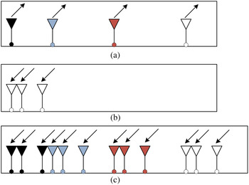
can be synthesized. Thus, we can create an MN-element virtual array with a large aperture by using only M + N physical antenna elements. Figure 1 shows an example of MIMO radar antenna arrays with M = 4 and N = 3.
Illustration of a MIMO radar system: (a) transmitting array, (b) receiving array, and (c) virtual array, with M = 4 and N = 3.

Correspondingly, the difference co-array (i.e. the spacing set) of the virtual array can be expressed as
 $$\eqalign{D_{VA} = & \{ \left. {x_{Ti} + x_{Rj} - (x_{Ti^{\prime}} + x_{Rj^{\prime}} )} \right \vert \cr i,i^{\prime} = & 1,2, \ldots, M;\quad j,j^{\prime} = 1,2, \ldots, N\}.} $$
Then, the redundancy R for MIMO arrays is defined as the number of possible Tx/Rx element pairs divided by the largest virtual array contiguous aperture L [Reference Dong, Li and Guo19]
 $$R = \displaystyle{{{}_{MN}C_2} \over L} = \displaystyle{{MN(MN - 1)} \over {2L}},$$
where p C q = p!/q!(p − q)! is the number of combinations of p items taken q at a time. In MR-MIMO array design, the idea is to form a co-array which is minimally redundant in spacings; that is, a co-array that captures all of the spacings with a minimum number of Tx/Rx element pairs (ideally, each element of a non-redundant co-array involves only a single Tx/Rx element pair, i.e. R = 1).
For a given total number of Tx/Rx elements, the MR-MIMO array design can be generalized as a multi-variable constraint optimization problem [Reference Dong, Li and Guo19],
 $$\mathop {\max} \limits_{\left\{ {x_{Ti}} \right\},\left\{ {x_{Rj}} \right\}} \quad L;\quad \quad s.t.\quad H(D_{VA} ) = 0,$$
where the objective function
 $L = \min \left\{ {l \notin D_{VA} \vert {\,1 \le l \le \max (D_{VA} )} } \right\} - 1$
, the constraint function H(D
VA
) denotes the number of holes (i.e. missing spacings) in the co-array and can be computed by
 $$H(D_{VA} ) = \sum\limits_{l = 1}^L {(l \in D_{VA} )}, $$
where (l ∈ D VA ) is equal to 0 if s belongs to D VA and 1 otherwise. Note that, the completeness of the co-array are required in order that a good point spread function with low sidelobe levels for imaging applications can be obtained [Reference Bliss and Forsythe1, Reference Karaman, Wygant, Oralkan and Khuri-Yakub10] or a covariance matrix can be estimated for direction of arrival estimation or adaptive beamforming [Reference Pillai, Bar-Ness and Haber9, Reference Pal and Vaidyanathan11].
In directly solving this optimization problem, there are some difficulties:
-
– Firstly, the inverse mapping from the difference co-array of the virtual array to Tx/Rx array configurations is analytically unknown.
-
– Secondly, there are only a few Tx/Rx array configurations that satisfy constraint H(D VA ) = 0. Furthermore, to find such an array configuration, a huge calculation burden is required even for a small number of Tx/Rx antennas because of the large synthesized virtual array aperture.
Usually, a numerical implementation described as follows for this problem is preferable: Given transmitting element number M and receiving element number N, an initial maximum aperture L of the synthesized virtual array is chosen to determine whether the Tx/Rx elements can be placed at the proper locations so that all the required spacings of the co-array are present, i.e. H(D VA ) = 0. If such Tx/Rx configurations are found, L can be increased and the procedure repeats until L grows too large. For such a numerical implementation, stochastic optimization techniques (e.g. PSO in [Reference Rezer, Gropengießer and Jacob12]) seem good candidates because of their flexibility and generality. Theoretically, they allow to effectively explore the whole solution space and to figure out optimal MIMO array layout. However, it is very difficult to find a satisfactory solution after a number of iterations due to the exponentially explosive solution space (e.g. when large MIMO array designs are at hand). Fortunately, the introduction of analytical binary sequences known as CDSs [Reference Dong, Li and Guo19, Reference Dong, Shi, Lei and Guo20] presents a deterministic thinning methodology for MR-MIMO array synthesis. This CDS-based methodology can analytically determine the locations of Tx/Rx elements and therefore is not affected by convergence problems whatever the array size. However, the provided solutions of MR-MIMO array are limited due to the finiteness of obtainable CDSs [Reference Baumert21–Reference Gordon23]. In this paper, we resort to the combination of an ACO-based stochastic optimizer with a CDS-based method for a rapid and numerically-effective exploration of the search space.
III. HYBRID SYNTHESIS METHOD
The objective of the synthesis is to find in a computationally efficient way the optimum Tx/Rx array configurations in terms of the contiguous virtual array aperture. Towards this end, we propose a hybrid optimization method. In order to point out the arguments that justify an integrated strategy, the key features of the CDS-based method and of the ACO-based synthesis technique are firstly discussed. Then, the integrated procedure is carefully described.
A) CDS-based method
CDSs are combinatorial methods initially investigated in combinatorial mathematics and information theory [Reference Baumert21–Reference Gordon23] and later applied to antenna array optimization [Reference Leeper13–Reference Kwon, Hwang, Park, Kim and Kim15, Reference Dong, Li and Guo19, Reference Dong, Shi, Lei and Guo20].
A CDS D(V, K, Λ) is a set of K integers {d j } [Reference Baumert21, Reference Hall22]
 $$0 \le d_1 \lt d_2 \lt \cdots \lt d_K \lt V,$$
such that any integer v (0 < v < V) can be represented exactly Λ times in the form
 $v \equiv d_j - d_i \;(\bmod \;V)$
, where “mod V” means the difference is to be taken modulo V. The parameters (V, K, Λ) of any CDS are connected by
 $$K(K - 1) = {\it \Lambda} (V - 1),$$
and so there are only two independent parameters among V, K, and Λ. Given a CDS D(V, K, Λ), the set
 $$D^{\prime} = \{ d_1 + s,d_2 + s, \cdots, d_K + s\} \equiv D + s,$$
where each element is taken modulo V, will also be a (V, K, Λ) difference set. In this case, D’ is called a cyclic shift of D. If D p and D q are two difference sets with the same parameters (V, K, Λ) and D p = tD q + s for any integers t and s with t prime to V, then D p and D q are called equivalent difference sets. For any particular (V, K, Λ) satisfying (7) there may be no difference sets, one difference set (disregarding equivalent sets), or several nonequivalent difference sets.
The most attractive feature of a CDS originates from its autocorrelation function expressed as [Reference Leeper13]
 $$C(\tau ) = \sum\limits_{k = 0}^{V - 1} {a_k} a_{k + \tau} = \left\{ {\matrix{ {K,} & {{\rm if}\,\tau (\bmod \,V) = 0} \cr {\Lambda,} & {{\rm otherwise}} \cr}} \right.,$$
where
 $$a_k = \left\{ {\matrix{ {1,} & {{\rm if}\,k(\bmod \,V) \in D} \cr {0,} & {{\rm otherwise}} \cr}} \right..$$
It can be seen from (9) that the autocorrelation function of a CDS is “two-valued”. Ultimately, it is this property that makes CDSs an effective prescription for the design of MR-MIMO arrays. In [Reference Dong, Li and Guo19, Reference Dong, Shi, Lei and Guo20], we demonstrated that by placing Tx/Rx elements at the CDS-derived locations, a very large virtual array aperture can be synthesized and the uniformity of its difference co-array is guaranteed by CDSs’ autocorrelation property.
The M × N CDS-based MR-MIMO arrays are constructed as follows,
 $$\eqalign{& \{ x_{Tm} \} = \{ b_m \cdot V\} \cr & \{ x_{Rn} \} = \{ d_n \},} $$
where {d n } is a CDS with the parameters (V, N, 1), n = 1,…,N, d 1 = 0 is specified; Λ = 1 is specified to ensure the synthesized contiguous aperture L as large as possible; {b m |0 ≤ b m ≤ P, m = 1, 2, …, M} is a difference basis [Reference Leech25] for a (0, P) segment such that any integer from this segment can be expressed as a difference b m –b m’ . In fact, an M-element difference basis corresponds to an M-element MR linear array in the transmitting only or receiving only scenario [Reference Linebarger, Sudborough and Tollis26].
The CDS-based method is a powerful analytical technique for the MR-MIMO array synthesis. However, such efficiency depends on the availability of a CDS for whatever size of the array [Reference Leeper13–Reference Kwon, Hwang, Park, Kim and Kim15]. Although several families of CDSs have been determined and extensive collections are also available [Reference Gordon23], it is well known that there is no corresponding CDS for several K values [Reference Baumert21, Reference Hall22] (i.e. it is not possible to define a binary sequence with a two-level periodic autocorrelation of length K).
B) ACO-based method
ACOs are stochastic multiple-agents optimization algorithms recently applied in the framework of antenna array optimization [Reference Rocca, Manica and Massa27–Reference Oliveri, Rocca, Poli, Carlin and Massa31]. The underlying concept of ACOs was originated by imitating the collective behavior of ants choosing an optimal path between the nest and the food source. In a colony, each ant affects the path choice of the others by marking the path it follows with a chemical called pheromone, producing a positive feedback for the shortest path. The application of ACOs in the MR-MIMO array design could come from the agent-based technique and also from its simplicity in optimization procedure. The former means that ACOs produce many optimized configurations simultaneously and allow for potential parallel implementation in modern computers. The latter means ACOs are most effective for the discrete nature of the problem at hand and do not need encoding or decoding operations on chromosomes as in GAs or PSO [Reference Rezer, Gropengießer and Jacob12].
In each iteration, each ant constructs an (M + N)-node path representing a candidate solution by applying the random proportional rule
 $$P_m^k (t) = \left\{ {\matrix{ {\displaystyle{{\left[ {\tau _m (t)} \right]^\alpha \left[ {\eta _m (t)} \right]^\beta} \over {\sum\nolimits_{s \in J^k} {\left[ {\tau _s (t)} \right]^\alpha \left[ {\eta _s (t)} \right]^\beta}}}} & {m \in J^k} \cr 0 & {{\rm otherwise}} \cr}} \right.,$$
where
 $P_m^k (t)$
is the probability of a given node m to be chosen for a path by ant k at iteration t, τ
m
is the pheromone level of node m, η
m
is the heuristic information of node m, and Jk
is the tabu list of nodes still to be visited by ant k. The parameters α and β are weights balancing the relative influence of the pheromone trail and the heuristic information. In particular, the heuristic information in this problem is related to number of holes in the difference co-array of virtual array, i.e.
 $$\eta ({\bf X}) = {1 / {H(D_{VA} )}},$$
where X = [X T ; X R ] = [{x Ti };{x Rj }] denotes the candidate solution constructed by an ant. The inclusion of this heuristic information will guide the ant-based solution construction and obviously improve solution quality but at the cost of much added computational expense.
In principle, ACO-based strategies allow to effectively explore the whole solution space and to figure out the optimal MR-MIMO layout with any given number of antennas. However, if a-priori information is not available and/or exploited, a satisfactory solution can be found only after a non-negligible number of iterations. Clearly, the computational burden grows with the dimension of the solution space (e.g. when large arrays are at hand).
C) Hybrid optimization strategy
The considerations outlined in the previous subsections suggest that an improvement could be achieved by integrating the CDS-based method into the ACO optimization process. More specifically, the limited quantity of MR-MIMO array configurations in the CDS-based method could be enriched by ACO global search capability, while the uniform difference co-array of CDS-derived schemata could be helpful to speed up the convergence of the ACO procedure.
One possible way is to consider CDS-derived schemata as a-priori knowledge to be inserted in the ACO search process in order to improve its efficiency. Like CDS-based method expressed in (11), we fix the receiving array by a CDS. Then the reference transmitting array in the CDS-based method is used as the local heuristic information to guide the ant-based solution construction while maintaining global search capability by pheromone level updating. The hybrid optimization strategy is described as follows:
1) CDS SELECTION AND INITIALIZATION
At the initialization step, the element locations of the receiving array (or the transmitting array, usually the array with a relatively larger number of elements) are fixed as a CDS, i.e.
 $${\rm \bf X}_R = {\rm \bf X}_R^{CDS} = D^{(\sigma )} (V,K,{\it \Lambda} )\left \vert {_{K = N,{\it \Lambda} = 1}} \right. = D^{(\sigma )} (V,N,1),$$
where Λ = 1 is specified to ensure the synthesized contiguous aperture L as large as possible;
 $D^{(\sigma )} = \{ d_j^{(\sigma )} \in {\bf {\opf Z}}^V, j = 1, \ldots, N;\quad \sigma = 0, \ldots, V - 1:d_j^{(\sigma )} = (d_j + \sigma )\left\vert {_{\bmod \;\;V}} \right.\} $
is the σ-th cyclic shift difference set. With an enumerative shifting procedure developed in [Reference Dong, Shi, Lei and Guo20], we can quickly find out the optimal CDS with respect to L for given parameters (V, K, Λ). Note that, CDSs with Λ = 1 only exist for K = q + 1 [Reference Baumert21, Reference Hall22], where q is a prime or a power of a prime. When there are no such CDSs D(V, N, 1), in order to make our method applicable for any given number of elements, a CDS with the parameters (V
CDS
, KCDS
, 1) (where K
CDS
is smaller than N but very close to N) can be assumed as the starting point of the receiving array for the optimization process. Then, the remaining N-K
CDS
receiving elements can be randomly inserted at any vacant position between 0 and V.
With this initialization, a significant advantage is the highly reduced dimension of the search space because only the transmitting array needs to be constructed by the ACO process. Consider an M × N MIMO radar with the largest virtual array aperture L. The total number N t of possible configurations (i.e. the dimension of the solution space) can be computed as
 $$N_t = {}_LC_{M - 1} \cdot {}_LC_{N - 1}, $$
where
p
C
q
= p!/q!(p − q)! is the number of combinations of p items taken q at a time; In particular, x
T1 = 0 and x
R1 = 0 is specified. Let us define
 $N_t^c $
as the total number of possible configurations with the constraint of (14) and it can be evaluated as
 $$N_t^c = {}_LC_{M - 1}. $$
For example, assuming a MIMO radar with M = 3, N = 5, and L = 63 [Reference Chen and Vaidyanathan7], we have N
t
≈ 1.16 × 10⁹ and
 $N_t^c \approx 1.95 \times 10^3 $
. It is clear that the total number of tries is drastically reduced by introducing the constraint of (14).
2) ACO-OPTIMIZATION
At each iteration, the ant-based optimization for the transmitting array takes place through path construction and pheromone update taking into account the following simplified heuristic information
 $$\eta = {1 / {\left \vert {{\rm \bf X}_T - {\rm \bf X}_T^{ref}} \right \vert}}, $$
where
 $\left\vert {{\rm \bf X}_T - {\rm \bf X}_T^{ref}} \right\vert$
denotes the distance of the currently constructing transmitting array X
T
away from the reference transmitting array
 ${\rm \bf X}_T^{ref} $
in the CDS-based method. By applying (17) as the heuristic information, it can be expected that the ant-based solution construction would be greatly speeded up because of the use of a-priori geometrical information and the reduced neighborhood for the current solution component.
3) TERMINATION
Given transmitting element number M, receiving element number N, and the initial maximum virtual array aperture L, the iterative optimization terminates when the constraint H(D VA ) = 0 is satisfied.
Both mechanisms in (14) and (17) are aimed at constraining ACO to search Tx/Rx array configurations similar to CDS-based ones, but with richer configuration choices due to swarm-based optimization strategies. Therefore, with our hybrid optimization strategy, the convergence of the ACO procedures will be greatly speeded up because of the highly reduced dimension of the search space and the CDS-guided local information. On the other hand, the global search capability of this hybrid method is maintained thanks to the ACO-based optimization. Moreover, the computational cost is greatly reduced because of the fixed receiving (or transmitting) array and the simplified heuristic information.
IV. NUMERICAL VALIDATION
In the following, numerical results will be presented and compared with those obtained by the previous methods [Reference Wang, Shao and Cai6, Reference Chen and Vaidyanathan7, Reference Dong, Li and Guo19] and the basic ACO, pointing out the advantages of our hybrid optimization strategy. The assumed parameters for the ACO-based procedures are α = 1 (weight of pheromone level), β = 5 ~ 10 (weight of heuristic information), ρ = 0.02 (pheromone decay rate), and
 $N_{ant} = \left\lfloor {L/(MN)} \right\rfloor $
(number of ants). These algorithm parameters have been chosen on the ground of several preliminary simulations [Reference Dong, Li, Jin, Zhu, Huang and Gui30]. In fact, the inclusion of CDSs knowledge makes an accurate tuning of ACO parameters not necessary. Since the CDS-based planar MR-MIMO array can be easily generated by “multiplying” two orthogonal CDS-based linear MR-MIMO arrays [Reference Dong, Li and Guo19], the following numerical studies will be focused on the linear MR-MIMO array synthesis.
Experiment #1: The first experiment deals with MR-MIMO array synthesis with a small number of Tx/Rx antennas (M = 3, N = 5). As a matter of fact, the design of a 3 × 5 MR-MIMO array is equal to the synthesis of a 15-element MR virtual array for a given maximum contiguous aperture L. In this case, an ES seems feasible for finding a MR-MIMO array due to the not very high size of search space. In [Reference Chen and Vaidyanathan7], a solution was given by an exhaustive search: {x Ti } = {0, 1, 3}, {x Rj } = {0, 6, 13, 40, 60}, and the resulting virtual array with L = 63 is VA = {0, 1, 3; 6, 7, 9; 13, 14, 16; 40, 41, 43; 60, 61, 63}. Also, an optimal CDS-based solution can be obtained from [Reference Dong, Li and Guo19, Reference Dong, Shi, Lei and Guo20]: {x Ti } = {0, 21, 63}, {x Rj } = {0, 3, 4, 9, 11}, and the resulting virtual array with L = 72 is VA = {0, 3, 4; 9, 11, 21; 24, 25, 30; 32, 63, 66; 67, 72, 74}. This solution is the best solution found up to date. Note that, the spacing of 73 is missing in this virtual array.
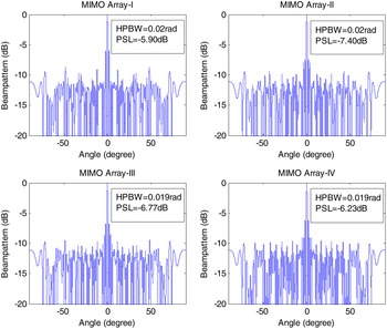
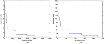
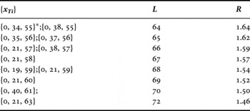
In the framework of our hybrid strategy, given the receiving array as {x Rj } = {0, 3, 4, 9, 11}, which is an optimal CDS with the parameters (21, 5, 1) obtained from [Reference Dong, Shi, Lei and Guo20], Table 1 presents several solutions obtained by the proposed method. All these solutions are superior to that obtained by the ES [Reference Chen and Vaidyanathan7] in terms of the maximum contiguous aperture L and the redundancy R of the virtual array, meaning higher spatial resolution and a larger number of available degrees of freedom. Figure 2 shows the comparison of beampattern characteristics (e.g. half power beamwidth (HPBW) and PSL) for four selected MR-MIMO array configurations. These MR-MIMO arrays with similar HPBWs have significantly different sidelobe performances, which would be helpful to the selection of proper configurations in antenna engineering applications. Basically, MR-MIMO arrays exhibit higher sidelobe levels compared with uniform MIMO arrays because of heavily thinning and an optimized weighting of array elements is often required in order to obtain a virtual array response with low sidelobes. Figure 3 shows the convergence of the basic ACO and our hybrid optimization method, respectively. Obviously, the convergence rate of the optimization process improves when using the hybrid strategy as compared with the bare ACO approach. Moreover, the blindness of the start of the bare ACO search is significantly reduced with the guide of the quasi-CDSs-based structure.
The comparison of beampatterns for four selected MR-MIMO array configurations. MIMO Array-I: {x Ti } = {0, 19, 59}, {x Rj } = {0, 3, 4, 9, 11}, and L = 68. MIMO Array-II: {x Ti } = {0, 21, 59}, {x Rj } = {0, 3, 4, 9, 11}, and L = 68. MIMO Array-III: {x Ti } = {0, 40, 61}, {x Rj } = {0, 3, 4, 9, 11}, and L = 70. MIMO Array-IV: {x Ti } = {0, 21, 63}, {x Rj } = {0, 3, 4, 9, 11}, and L = 72.

Minimum number of holes versus the number of iterations by using the basic ACO (a) and the hybrid optimization method (b), respectively.

Solutions of MR-MIMO linear arrays obtained by the proposed method (M = 3, N = 5, {x Rj } = {0, 3, 4, 9, 11}).

* Mirror image arrays are considered equivalent, e.g. {0, 34, 55} and {0, 21, 55} are the same transmitting array.
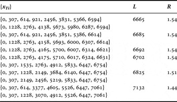
Experiment #2: Dealing with the application of the hybrid method to a higher complexity problem with a larger solution space, let us consider the MR-MIMO array synthesis with M = 8 and N = 18. As a matter of fact, the design of an 8 × 18 MR-MIMO array is equal to the synthesis of a 144-element MR virtual array for a given maximum contiguous aperture L. In this case, an ES or a bare stochastic optimizer seems powerless for finding MR-MIMO arrays due to the extremely large search space (e.g. being of the order of 1074 according to (15) when L = 7000) and the rigid constraint function (i.e. H(D VA = 0) in (4)). Given {x Rj } = {0, 12, 14, 34, 43, 59, 67, 80, 97, 103, 107, 108, 159, 178, 185, 217, 220, 235}, which is an optimal CDS with the parameters (307, 18, 1) obtained from [Reference Dong, Shi, Lei and Guo20], Table 2 presents a small portion of solutions as well as their performances obtained by the proposed method. It can be seen that these MR-MIMO array configurations with a modest number of physical antennas can produce huge virtual array apertures, meaning very few redundant spacings and very high spatial resolutions.
Solutions of MR-MIMO linear arrays obtained by the proposed method (M = 8, N = 18, {x Rj } = {0, 12, 14, 34, 43, 59, 67, 80, 97, 103, 107, 108, 159, 178, 185, 217, 220, 235}).

Experiment #3: To further confirm the effectiveness of our hybrid method, a representative example is performed by choosing M = 4 and N = 7. In this case, no CDS sequence with the parameters (43, 7, 1) is known or available (because 7 cannot be expressed as the sum of 1 and a prime or a power of a prime [Reference Baumert21–Reference Gordon23]) and therefore the CDS-based method seems not workable. On the other hand, a satisfactory solution of a 4 × 7 MR-MIMO array can only be found by a “bare” ACO search after a huge number of iterations considering the exponentially explosive computational burden (e.g. being of the order of 1017 according to (15) when L = 200) and the rigid constraint function in (4).
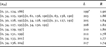
In the framework of our hybrid strategy, a CDS with the parameters (31, 6, 1), e.g. D(31, 6, 1) = {0, 1, 4, 10, 12, 17}, can be assumed as the starting point of the receiving array for the optimization process. Then, the remaining one receiving element can be inserted at any vacant position between 0 and 43. By choosing {x Rj } = {0, 1, 4, 10, 12, 17, 32}, Table 3 presents a small portion of solutions obtained by the hybrid optimization procedure. It can be observed that our hybrid method greatly enriches actually obtainable MR-MIMO array configurations despite no availability of CDS sequence for some particular parameters (V, K, Λ) and thus extends applicability of the CDS-based method.
Solutions of MR-MIMO linear arrays obtained by the proposed method (M = 4, N = 7, {x Rj } = {0, 1, 4, 10, 12, 17, 32}).

* The best solution obtained by CDS-based method [Reference Dong, Li and Guo19] in 4 × 6 MR-MIMO array synthesis also has L = 199.
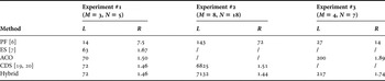
To summarize, Table 4 presents the comparison of MIMO arrays in terms of L and R between our hybrid method and other previous methods. In the PF-based method [Reference Wang, Shao and Cai6], a uniform virtual array is synthesized and its maximum contiguous aperture is determined by MN-1. As far as the spatial resolution performance is concerned, the PF-based method seems not a good candidate compared with the other designs aiming at a maximally thinned virtual array. Due to the exponentially explosive search space, an ES [Reference Chen and Vaidyanathan7] can only provide good solutions for Experiment #1 within reasonable iteration time. By introducing the multiple-agents optimization strategies, ACO shows global search capability and provides good solutions for Experiment #1 and #3. However, the computational burden strongly increases with the rising thinning rate (see (15)), which itself becomes not acceptable for the designs with a relatively large number of elements (e.g. Experiment #2). The CDS-based method [Reference Dong, Li and Guo19, Reference Dong, Shi, Lei and Guo20] can provide satisfactory solutions for Experiment #1 and #2 at a very small computational cost because of its analytical construction procedures. However, since no CDS sequence is available for Experiment #3, the CDS-based method becomes infeasible in this case. By combining the attractive features of CDS and ACO, the hybrid method can obtain satisfactory solutions in a computationally effective way for all the three cases.
Comparison of MIMO arrays between the hybrid method and other previous methods.

Further, in order to give an idea of computational efficiency in the above experiments, Table 5 presents the comparison of computational cost between the basic ACO and the hybrid method. In this table, each iteration time τ i , total run time τ total , and iteration number I are listed. All the reported values have been obtained by averaging over 20 trials. We performed the simulations in the following experimental environment:
-
– —CPU: 3.2 GHz Intel®Core™
-
– —RAM: 4GB DDR
-
– —Language: MATLAB 2012
Comparison of computational cost between basic ACO and the hybrid method.

In conclusion, all these experimental results have demonstrated that the proposed method outperforms the CDS-based method [Reference Dong, Li and Guo19, Reference Dong, Shi, Lei and Guo20] in terms of the generality and configuration variety, and outperforms the stochastic optimization methods (e.g. ACO and PSO [Reference Rezer, Gropengießer and Jacob12]) in terms of convergence rate and computational cost.
V. CONCLUSION
In this paper, a hybrid optimization method devoted to the MR-MIMO array synthesis has been presented. The proposed method exploits and combines the positive features of the combinatorial techniques and of the stochastic optimization techniques to obtain in a computationally effective way the best solution in terms of MIMO virtual array aperture. Numerical tests have been performed showing that the hybrid method outperforms the CDS-based method in terms of the generality and configuration variety, and outperforms the stochastic optimization methods in terms of convergence rate and computational cost.
Future works will be aimed at extending the proposed method to MIMO array synthesis with more complex and realistic scenarios. Moreover, other analytical sequences with good autocorrelation properties (e.g. ADSs, Hadamard difference sets [Reference Kopilovich32], and McFarland difference sets [Reference Oliveri, Caramanica, Fontanari and Massa33] which greatly extend the range of applicability of combinatorial methods) will be investigated to verify their advantages and potentialities for MIMO radar array designs.
ACKNOWLEDGEMENT
This work was supported in part by the National Science Foundation of China under project number 61201086 and 61379153, in part by the Doctoral Fund of Ministry of Education of China under project number 20110162120044, in part by the China Scholarship Council under project number 201506375060, and in part by the Planned Science and Technology Project of Hunan Province under project number 2014GK3022.
 Jian Dong received his B.S. degree in Electrical Engineering from Hunan University, Changsha, China, in 2004, and the Ph.D. degree in Electrical Engineering from Huazhong University of Science and Technology, Wuhan, China, in 2010. He is now an associated professor at the School of Information Science and Engineering, Central South University, Changsha, China. He has authored more than 50 research articles and his present research interests include antenna arrays, microwave remote sensing, and numerical optimization techniques for electromagnetic problems.
 Ronghua Shi received his Ph.D. degree from Central South University in 2007. He is presently a professor at the School of Information Science and Engineering, Central South University. He has authored more than 100 research articles and his present research interests include wireless communications, satellite communications, and antennas.
 Ying Guo received his Ph.D. degree from Shanghai Jiao Tong University, Shanghai, China, in 2006. He is presently a professor at the School of Information Science and Engineering, Central South University. He has authored more than 80 research articles and his present research interests include wireless communications, information theory and coding theory.