Introduction
The instrumentation of projectiles equipped with various sensors and telemetry units is of great interest for decades, in particular to support aerodynamic and ballistic research [Reference Kingey1–Reference Barton3]. The main challenges when designing such telemetry antennas are to combine the mechanical and electromagnetic (EM) properties of the structure in order to ensure resilience to the high accelerations during the firing (typically between 10 000 g and 70 000 g during 10 ms) and to centrifugal forces during the flight (spin rate up to 1000 Hz typically).
This paper focuses on the design steps of an asymmetric coaxial dipole at 2300 MHz for a projectile of caliber 30 mm, referred to as Secant Ogival Cylinder Boat Tail (SOCBT) [Reference Decrocq, Martinez, Albisser, Dobre, Gnemmi, Bailly and Roy4]. When fired from a 30 mm rifled gun at Mach 2.5, the maximum acceleration is about 36 000 g with a spin rate of 1200 Hz and maximum angles of attack of about 5°. The design must ensure the resistance of the antenna against these extreme conditions.
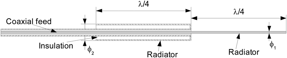
The antenna is located in the fuse of the projectile and is inspired by the well-known coaxial dipole architecture [Reference Bailey5], depicted in Fig. 1. The advantage of this structure is the feeding by a coaxial cable passing through one of the two radiators; the second one may be constituted of the inner conductor itself (outer shield is removed on this part). The length of each radiator is a quarter of the wavelength at the resonance frequency. This architecture is compact and symmetrical with respect to the roll axis as long as the radiators are cylindrical. The matching to the coaxial cable impedance (50 Ω in general) depends among others, on the radiator diameters ϕ 1 and ϕ 2.
Coaxial dipole, inspired by [Reference Bailey5].

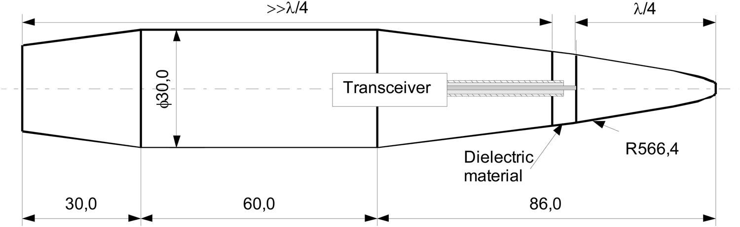
The first approach to integrate an antenna into the SOCBT projectile is described in Fig. 2. The fuse is cut into two parts constituting the two arms of a dipole. The first one (on the right) has a length of λ/4, whereas the second one is much longer (≈1.1 λ). Both are separated by a dielectric material and the feeding is done by a coaxial cable connected to the right arm.
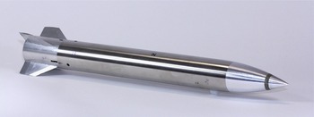
SOCBT projectile of caliber 30 mm and first approach to integrate the antenna.

In contrary to the classical projectile architectures, where the fuse is made out of steel or aluminum and the body is made out of cast iron, different materials are used here: A fiber-reinforced polymer is introduced into the structure as insulation material and the nose of the projectile is made of a brass alloy. Due to the modified materials and geometries, the maximum mechanical stresses in the antenna structure had to be evaluated during the design phase.
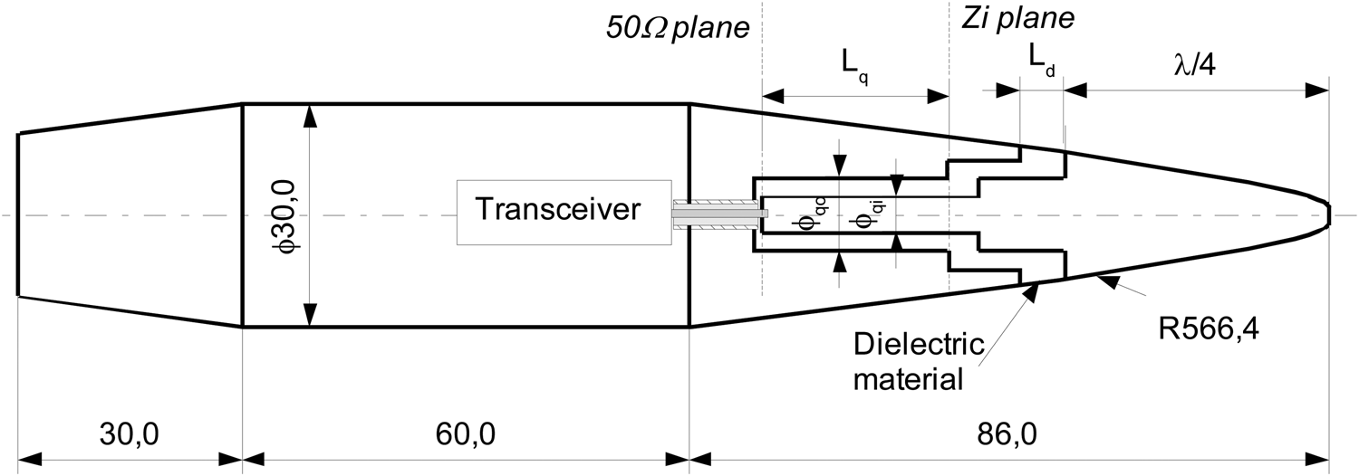
Therefore, the architecture has been updated and several additional steps were required before achieving the structure proposed in Fig. 3.
SOCBT projectile and final approach to integrate the antenna.

Mechanical and EM design
Extension of the quarter of wavelength arm
To increase the resistance to the transversal forces, the shorter arm of the dipole is extended in the dielectric material, as shown in Fig. 3. Indeed, this metallic part is much larger than the coaxial cable and is longer than the dielectric part between both arms of length L d. This dielectric part is also extended to keep the insulation between the metallic parts, respectively, connected to the inner and the outer conductors of the coaxial cable.
Selection of the dielectric material
In addition to its EM function, the dielectric part between the two metallic arms also contributes to the rigidity of the structure. Therefore, a material that allows a compromise between the mechanical and the EM constraints had to be found. In the end, 30% glass fiber-reinforced polysulfone (PSU-GF30) was retained because of its thermal capability and inherent flame resistance, as well as its improved mechanical properties, in comparison to Teflon, polypropylene or other polymer materials. The permittivity and dielectric losses of PSU-GF30 were estimated with a coaxial cell dedicated to the EM characterization of materials [Reference Georget, Abdeddaim and Sabouroux6]. The measurement was performed with hollow cylinder samples and finally, the permittivity was assessed to ɛr = 3.5, tanδ ~ 0.01 around 2300 MHz.
Matching the antenna to 50 Ω
The matching of the antenna is achieved by a quarter-wavelength coaxial line between the Zi plane and the 50 Ω plane; the coaxial cable connected to the transceiver is soldered to the metallic right arm in this plane. The length of the quarter-wavelength impedance transformer is L q, whereas the diameter of the inner conductor is ϕ qi and the diameter of the outer conductor ϕ qo.
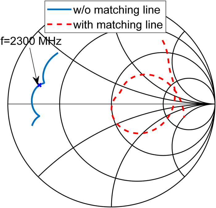
The simulated reflection coefficient in the Zi plane is represented in Fig. 4; for this simulation, the matching line is considered to have a length of L q = 0, and the coaxial cable (of impedance 50 Ω) is directly connected to the right arm in the Zi plane. At 2300 MHz, the impedance is Zi = 8.3 + j6.3 Ω. As a first approximation of the matching line dimensions, the following well-known equation is used [Reference Johnson7]:

Simulated reflection coefficient without (L q = 0) and with the quarter-wavelength transformer; frequency range [1500;3000] MHz.

It calculates the impedance viewed after a line of characteristic impedance Z q and of length L q, when terminated by the load Zi. To transform Zi = 8.3 + j6.3 Ω to 50 Ω, a line of characteristic impedance Z q = 19.3 Ω and of length L q = 25 mm is required. This result is taken as initial values for the optimization step with the full-wave solver HFSS [8].
The impedance of the quarter-wavelength line depends on the diameter of its inner and outer conductors ϕ qi and ϕ qo respectively, according to the following equation [Reference Johnson7]:

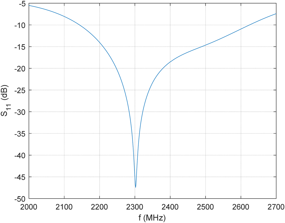
There are many couples (ϕ qiϕ qo) that are giving the same impedance. At this stage, the value ϕ qi = 3 mm is considered from the numerical mechanical simulation results (presented in the following section). After optimization, a matching line with L q = 17.8 mm, ϕ qi = 3 mm and ϕ qo = 5.5 mm is found to match the antenna at 2300 MHz. The simulated reflection coefficient with this matching line is given at Fig. 4 in the Smith chart and at Fig. 5 as magnitude in dB with an S11-bandwidth (S11-BW) of 480 MHz.
Simulated reflection coefficient with the quarter of wavelength impedance transformer.

Numerical mechanical simulations
In parallel to the EM design and simulation, static linear numerical simulations are performed to verify the rigidity of the geometry with the chosen materials under the given loads.
Since all loads are highly dynamic but in the first approximation only consist of one cycle, twice the elastic limit of the material is a good assumption for the maximum allowed material stress. The explanation why higher stress limits can be assumed is that material inertia acts against the deformation at high strain rates. This value proved to be a good assumption for load cases in the order of several milliseconds.
The loads applied during a standard firing can be separated into two simulation cases: The axial load due to the acceleration in the bore of the launcher and a normal force on the nose tip which creates flexion stress on the tip of the antenna assembly.
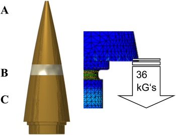
As shown in Fig. 6, the critical stress during axial acceleration load is concentrated on the notch region at the end of the thread which mounts part A on part B. This stress field originates in the weight of the pin constituting the inner conductor of the quarter of a wavelength, under the high acceleration. However, this stress is not leading to failure (detachment of part A during flight) since the threaded part of the steel pin assures the mechanical junction.
Antenna components under axial load – symmetric stress in a notch of part A at 36 000 g.

The axial load values during acceleration are an output value of the internal ballistics calculation and can be determined by using 0D-internal ballistics codes such as IntBal 1.0 [Reference Krcmar9]. The load case of flexion of the tip during the flight due to aerodynamic forces requires more expensive computational fluid dynamics. The maximum normal force is generated at the time of maximum angle of attack which is estimated here with 5° for normal flight conditions.
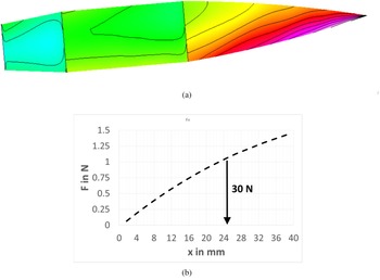
Figure 7(a) shows the aerodynamic pressure on part A at the moment of maximum angle of attack on the surface of the projectile. This pressure distribution creates a normal force distribution, as shown in Fig. 7(b), which can be reduced to a total force and the location of this total force (Fig. 8).
Load Estimation on Part A (a) Pressure distribution on projectile during maximum angle of attack in nominal flight, (b) Normal force distribution on part A and resulting force during flight (x = 0 equals theoretical SOCBT nose tip).

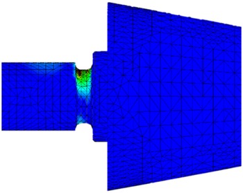
Antenna components under maximum flexion load – asymmetric stress in a notch of part A.

These values give a resulting momentum acting on the junction of part A and part B of approximately 0.5 N m.
The structural estimations did not indicate any mechanical failure of the antenna components.
EM characterization of the antenna
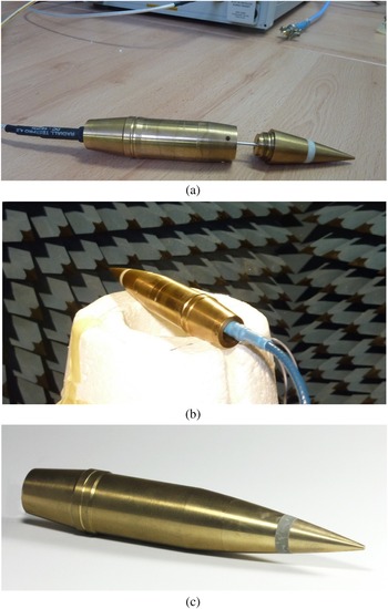
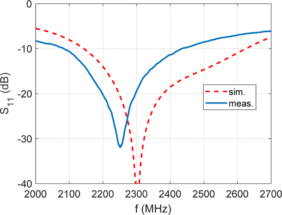
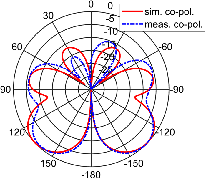
With the final retained architecture, S-parameters and far-field radiation were measured. Therefore, the antenna is assembled with a coaxial cable terminated by an SMA connector. It is then easy to connect the antenna to a vector network analyzer (VNA). To take into account the influence of the projectile body on the measurements, a hollow projectile is used with the feeding cable connected to the antenna passing through, as illustrated in Figs 9(a) and (9b). The measured reflection coefficient is given in Fig. 10; the antenna is well-matched around 2300 MHz (minimum of |S11| at 2251 MHz) with a measured S11-BW is of 349 MHz, covering more than the whole telemetry band ([2200;2400] MHz). This measured BW is narrower than the simulated one; nevertheless, the simulations were performed with a simplified geometry (in particular threads and notches were not considered). The measured radiation patterns at 2300 MHz are given in Fig. 11; these measurements are performed with an SG-24 near-field measurement system. The radiation is omni-directional with some ripples observed towards the rear of the projectile. They are due to the currents propagating on the longest arm of the dipole. In order to suffer at minimum from the radiation of the feeding cable in the anechoic chamber (see Fig. 9(b)), the horizontal plane (in the SG-24 coordinate system) is considered as a reference, since it is less affected by this disturbance. It is also to be noted that the feeding cable is oriented in the direction of radiation null at the rear of the projectile (towards 180°). A relatively good agreement with simulated radiation patterns is found with the maximum gain of 3.7 dB. This antenna fulfills the specifications to be used as an emitting antenna for projectile applications (2 MHz telemetry bandwidth in the telemetry S-band [2200;2400] MHz, antenna integrated into the projectile profile and designed to withstand the high accelerations and forces). The design has been successfully used in a test campaign with projectiles fired at Mach 1.5, up to initial accelerations of 12 000 g without structural failure. Additional firings are foreseen up to Mach 2.5. Figure 9(c) shows one of the manufactured antennas mounted on its own projectile. After assembling the antennas with SMA connectors and measuring their S-parameters and radiation performances, the 50 Ω coaxial is cut quite near to the antenna (the SMA connector is hence removed) and it is directly soldered on the transmitter board (input impedance of 50 Ω). The whole electronics, including batteries, are then enclosed in a real projectile (the antenna fuze is screwed to the front). The whole setup has then to be g-hardened before performing the firings.
Photographs of one of the manufactured antennas, (a) Antenna connected to the VNA with a hollow projectile, (b) Antenna in the anechoic chamber with a hollow projectile, (c) Antenna mounted onto the projectile (after having cut the coaxial cable and soldered it to the transmitter board).

Simulated and measured reflection coefficient.

Simulated and measured radiation patterns at 2300 MHz (nose towards 0° and rear towards 180°).

Receiving station
The payload of the projectile consists of several sensors such as gyros, accelerometers, magnetometers as well as pressure or temperature sensors. Up to 16 different sensors can be integrated and will be synchronously sampled to build up a data frame which will then be transmitted to a receiving station. In the past, we used dedicated telemetry hardware providing different functionalities like receivers, demodulators or bit-synchronizers. Even though these systems have excellent performance, they are very expensive, heavy, difficult to setup and did not meet our demands for remote control and automated processing. In addition, they are limited in terms of frequency and do not support modern modulations like OFDM.
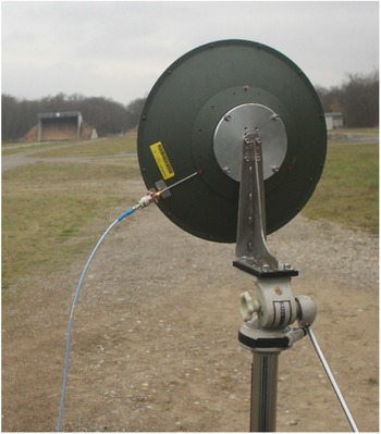
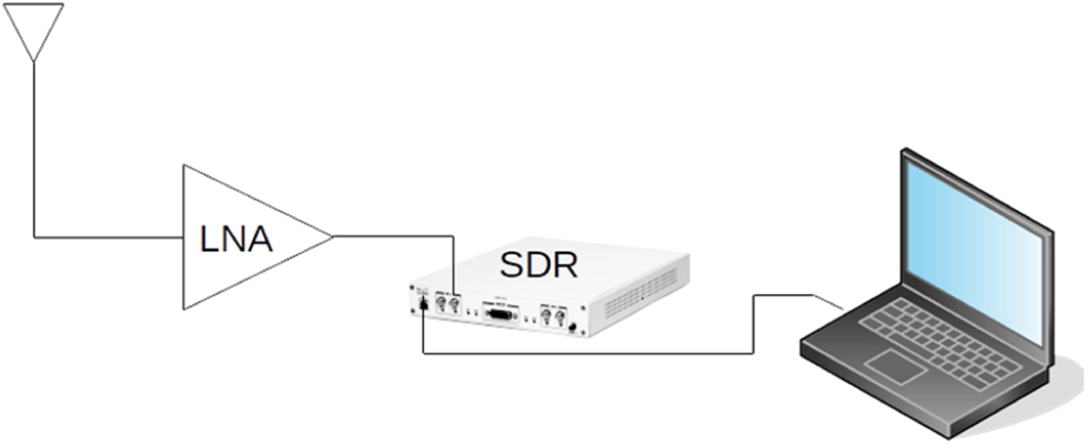
The receiving station described here is based on a very flexible and inexpensive commercial reception system based on a Software Defined Radio (SDR) from Ettus Research. The RF daughterboard of the SDR covers a frequency range from 10 MHz to 6 GHz. The setup of the receiving station using this SDR is straightforward: the RF signal is captured with a high-gain antenna (Fig. 12), sent through a low noise amplifier to the SDR. The amplified RF signal is down-shifted to the baseband, digitized with 200 Msamples/s within the SDR hardware and down-sampled to 25 Msamples/s before being sent to a PC for further processing with GNU Radio. Figure 13 shows a block diagram of the reception system.
High gain circularly polarized antenna.

Reception system.

The GNU Radio block implements a low-pass filter with a cutoff frequency at 1.5 MHz. The baseband signal is then demodulated using the “Quadrature Demod” block shown in Fig. 14. The demodulation block can be simply replaced by any other demodulator available in GNUradio. It is even possible to design new demodulator blocks.
GNU radio processing block.

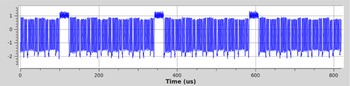
Figure 15 shows the baseband signal after the low pass filter and Fig. 16 the demodulated signal after the demodulator. The demodulated signal is stored in a file which is then further processed to finally recover the sensor data.
Baseband signal after low pass filter.

Demodulated signal.

Example of firing data
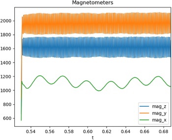
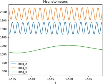
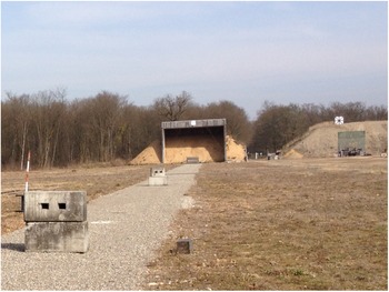
In the following, an example of firing data is given for a projectile with a spin of 720 Hz. The received data are shown below in Figs 17 and 18. The flight time was approximately 970 ms. The signals of the radial magnetometers (mag_y and mag_z) are sinusoidal (see Fig. 18), corresponding to the spin of the projectile during its flight. The axial magnetometer (mag_x) oscillates with the projectile pitch. As can be seen in Fig. 18, the radial magnetometers show the expected phase shift of 90°. Figure 19 show part of the firing line with the sand bay at the end for projectile recovery.
Magnetometer data.

Magnetometer data (zoomed).

Sand bay for projectile recovery.

Extension of the antenna concept to other projectiles
In this section, a few other projectiles are presented for which the dipole antenna concept is extended to instrument them.
Air Force finner
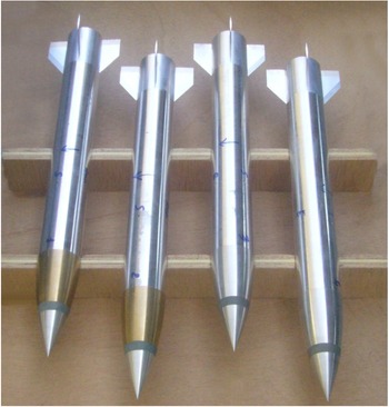
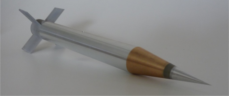
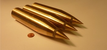
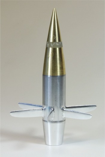
The Air Force finner projectile in body diameter 30 mm was fired from two of ISL's 90 mm launchers while the 48 mm version which served as a testbed for more voluminous electronic components was launched from a 105 mm launcher. Most tests were performed at transonic and low subsonic speeds of Mach 1.7 up to an acceleration maximum of 25 000 G's (Figs 20–25).
Air Force finner projectiles with antennas in brass and aluminum alloy (30 mm caliber).

Air Force finner projectile of caliber 48 mm with an ogival antenna.

Basic finner projectile of caliber 28 mm with a conical antenna.

40 mm projectile with cone antenna.

Army Navy spinner rocket with an antenna in front (caliber 40 mm).

Instrumented long-range projectile with fins (caliber 25 mm).

Basic finner
The basic finner standard model was used with slight modifications for multiple free-flight tests at ISL with initial Mach numbers of up to 3.0. Due to its acceleration in a large bore launcher, these firings were possible with maximum accelerations of 15 000 G's. The results of these measurements were used for various research projects at the institute.
40 mm Projectile
Similar to the previously presented 30 mm SOCBT architecture, an early version of the presented dipole antenna was applied in a 40 mm spin-stabilized projectile in 2009.
This projectile endured 15 000– 20 000 G's during 4 shots at low supersonic speeds of about Ma = 1.4. Spinrates during these free flight test varied slightly around 435 Hz.
Army navy spinner rocket
This projectile is of caliber 40 mm and of length 200 mm. The antenna BW is typically of 400 MHz.
Long-range projectile with fins
To experimentally validate the aerodynamic performances of gliding projectile with an extended range, a down-scale model of caliber 25 mm was instrumented with various sensors, telemetry and a front antenna.
This architecture was fired 18 times at subsonic speeds with accelerations between 5000 and 6000 G's. The test campaign took place in the year 2017. The scientific results of the firings can be found in [Reference Decrocq, Martinez, Juncker, Berner, Leopold, Bailly and Roy10, Reference Albisser, Dobre, Decrocq, Saada, Martinez and Gnemmi11].
Conclusion
A small telemetry antenna is presented, which was integrated into a projectile of caliber 30 mm. The design steps of this asymmetrical coaxial dipole are presented, from the EM point of view as well as from the mechanical one. The proposed design withstands the harsh conditions during projectile launch and the S parameters test results presented show a BW of about 350 MHz and a gain of 3.7 dB with an omnidirectional radiation pattern.
The receiving station was realized with an SDR, which largely reduces size, weight, and power. It is much easier to setup and completely flexible concerning modern modulation schemes.
This concept of the antenna was extended to various other projectiles for instrumented firings.
 Loïc Bernard graduated in electronics and communication systems from the National Institute of Applied Sciences (INSA) of Rennes, France in 2000. After this engineer degree, he received the Ph.D. degree in electrical engineering from INSA of Rennes, France in 2003. He joined the French-German Research Institute of Saint-Louis (ISL), France, in May 2004, as a research scientist. He received the “Habilitation à Diriger des Recherches” degree from the University of Rennes 1, Rennes, France in 2017. He is involved in the electronics instrumentation of flying systems with very high dynamics for aerodynamic and ballistic research; his research interests are focusing on antennas and antenna arrays, microwave circuits and meta-materials.
 Hrvoje Covic graduated in communication and information technology from the Faculty of Electrical Engineering, Mechanical Engineering and Naval Architecture (FESB) of Split, Croatia in 2013. He joined the French-German Research Institute of Saint-Louis (ISL), France, in June 2016, as a development engineer. He is involved in the development of the miniaturized microwave electronics used in flying systems with very high dynamics for aerodynamic and ballistic researches. His area of expertise lies in the area of microwave circuits, electronics, antennas and antenna arrays.
 Andreas Zeiner got his Master of Science in aerospace engineering at the Technical University of Munich in 2013. During his studies, he spent 6 months as an intern at EADS Astrium Space Transportation in Ottobrunn before finalizing his studies with a Master Thesis at Purdue University in the United States. He works at ISL since 2014 as an engineer for exterior ballistics and is involved in the free flight campaign preparation, prototype design and engineering support for ISL's laboratory launcher.
 Armin Schneider received his MSc in physics 1987 from the Fachhochschule Ravensburg-Weingarten. In 1988 he joined the French-German Research Institute of Saint-Louis. He is responsible for hard- and software development in the area of sensors, telemetry and communication systems. In 2001, he stayed at the École Polytechnique dé Montréal (Canada), where he participated in the development of a generic network processor. His current research interests are in the area of real-time signal processing, embedded systems, wireless communication systems and GNSS systems for defense and security applications.