Introduction
Research in the biomedical field has seen the development of small, durable, and low-power consumption types of communication systems to support implantable medical devices like pacemakers, neural stimulators, and biosensors [Reference Aldhaibani, Mohammed, Mahmood and Sellab1, Reference Alghanimi2]. These machines are based on incessant wireless communication of information between internal implantation and external monitoring devices in order to guarantee patient safety and the accuracy of treatment. Nevertheless, it is still challenging to have a stable connection of wireless communication in the human organism because of the high dielectricity of biological tissues, dynamic motions, and multipath attenuation of signals [Reference Alharbi, Moniruzzaman, Aldhaheri, Aljohani, Singh, Samsuzzaman and Islam3]. Traditional antenna designs can tolerate extreme detuning, a decrease in gain, and a high specific absorption rate (SAR), which deteriorate telemetry performance and are a safety concern [Reference Ali, Al Ghamdi, Iqbal, Khalid, Aldabbas and Saeed4, Reference Bhavani and Shanmuganantham5]. The submission of ultra-wideband (UWB) antennas has become a potential candidate for implantable telemetry due to their wide bandwidth, low transmission power, and high data rate [Reference Chehri and Mouftah6]. However, the vast majority of the mentioned designs are functioning within a very limited frequency spectrum, or they need very large structures that cannot be integrated into biomedical applications [Reference Cheraghinia, Shahid, Luchie, Gordebeke, Caytan, Fontaine and De Poorter7]. Moreover, their electromagnetic properties are very sensitive to the closeness of tissues and environmental fluctuation, and as such, resonant changes are not predictable, and impedance matching is erratic [Reference Dayo, Aamir, Dayo, Khoso, Soothar, Sahito and Guan8]. Such limitations, in turn, lead to a necessity for smart, adaptive antennas that could change the electric parameters of the antenna to ensure stable communication on the fly. Similar to the miniaturization of antennas, artificial intelligence (AI) and deep learning methods have shown much promise in wireless optimization problems, including channel prediction, adaptive modulation, and power control [Reference Debnath9–Reference Elmezughi, Salih, Afullo and Duffy11]. Recurrent neural networks (RNNs) and long short-term memory (LSTM) architectures are especially useful when modeled to do sequential signal modeling, and thus provide the possibility to predict the time-dependent characteristics of the channel accurately [Reference Faisal, Zada, Yoo, Mabrouk, Chaker and Djerafi12]. Their incorporation with implantable antenna systems to perform real-time adaptive tuning has, however, not been given much focus. A significant proportion of the current research is sometimes concerned with the optimization of a static geometry by evolutionary algorithm or by learning through reinforcement, without the inclusion of a closed-loop feedback down the line after the antenna has been deployed [Reference Ganesan and Iympalam13, Reference Gupta, Aljaidi, Bansal, Al Mamlook, Kumar, Aljohani, Aljohani and Singla14]. To overcome such limitations in this work, an adaptive multiband UWB antenna is suggested with a deep RNN-LSTM-based feedback mechanism to provide self-tuning during a pacemaker telemetry implantable system. The antenna suggested in this proposal uses a small fractal patch structure realized on polycarbonate material, which is biocompatible with low dielectric constant, is highly flexible, and has minimum SAR in the presence of tissues because of the low dielectric constant of the material. The antenna has multiband 2.4, 5.8, and 9 GHz capabilities with a strong communication link over low-rate control signaling and high-rate physiological data transmission. The deep learning version keeps the telemetry signals of the antenna, it predicts impedance variation due to tissue movement or to the position changes, and automatically modulates resonant parameters in response to these changes in position or tissue. This co-optimization between equipment and software has accomplished three key purposes: (i) the ability to maintain resonance stability in a dynamically challenging biological setting, (ii) the ability to achieve enhanced energy efficiency and radiation levels, and (iii) the ability to greatly reduce latency versus other more conventional fixed configuration systems. The simulation findings validate that the designed system achieves the return loss of −41.2 dB; the gain of 6.5 dBi; radiation efficiency of 88%; and the SAR of 0.72 W/kg, all of which are inside the exposure limits in the IEEE C95.1 [Reference Gupta, Kumari, Sharma, Alsharif, Uthansakul, Uthansakul and Bansal15]. The adaptive deep learning feedback guarantees 99% telemetry error and achieves lower latency, instead of 8 ms, as compared to traditional fixed and rule-based retuning.
The chosen study is innovative due to the incorporation of a robust RNN-LSTM learning engine and a UWB implantable antenna into real-time adjustable tuning. However, unlike traditional antenna designs, which utilize an offline optimization algorithm or a limited set of fixed geometries, the proposed system provides a closed-loop feedback system that predicts variations in impedance and shifts in resonance with tissue- or motion-driven variability. This is the implementation, which is the first one, whereby the direct coupling of temporal learning with the electromagnetic simulation is done to correct the antenna parameters dynamically. This is in addition to the fact that a biocompatible polycarbonate substrate is used further to improve safety and mechanical flexibility, since it does not affect gain or SAR compliance. The hybrid system will make the antenna an intelligent, self-optimized transceiver to provide telemetry with ultra-reliability and low latency that can be used in the next-generation implantable biomedical systems.
Major contributions
• Adaptive multiband UWB antenna design: A small fractal patch antenna is produced that works at 2.4, 5.8, and 9 GHz with the help of a biocompatible polycarbonate substrate. The design has a broad range of impedance bands and low SAR, which is favorable in implantable pacemaker telemetry.
• Deep RNN-LSTM-simulated signal adaptation: A temporal learning system that is based on data is presented to forecast and rectify impedance drift due to movement of tissues and differences in dielectric to allow dynamic resonance tuning without recalibration.
• Closed-loop intelligent feedback mechanism: The antenna and learning model are incorporated into a real-time feedback system, which makes adjustments to the tune of electrical parameters to maintain the conditions of low-latency and high-fidelity telemetry under changing physiological circumstances.
• Performance optimization and validation: It is demonstrated by electromagnetic simulation as superior performance: return loss of −41.2 dB, gain of 6.5 dBi, radiation efficiency of 88%, and SAR of 0.72 W/kg, which outperform conventional static and rule-based models.
Literature survey
UWB antennas have captured immense interest in the field of biomedical and healthcare applications, particularly in terms of their high data rate, wide frequency range, and ability to achieve precise, short-range wireless transmission [Reference Alghanimi2, Reference Mane16, Reference Sharma, Vijay and Shukla17]. Initial experiments showed that wearable textile and patch antennas have potential remarks on biomedical investigative applications with a low profile, flexible antenna designs working at 2.43 GHz with both dependable gain and reduced SAR [Reference Aldhaibani, Mohammed, Mahmood and Sellab1, Reference Bhavani and Shanmuganantham5, Reference Prasanna, Annaram and Venkatalakshmi18, Reference Tiwari, Gupta and Balyan19]. Such designs are referred to as wireless body area networks (WBANs) and allow real-time monitoring of patients [Reference Chehri and Mouftah6, Reference Yaghoubi, Ahmed and Miao20]. Recent evolution of UWB antennas of implantable systems has seen a reduction in bandwidth of over 100% and gains of up to 12 dBi with miniature designs on substrates like FR4, Rogers, and Teflon [Reference Faisal, Zada, Yoo, Mabrouk, Chaker and Djerafi12–Reference Gupta, Aljaidi, Bansal, Al Mamlook, Kumar, Aljohani, Aljohani and Singla14, Reference Yousaf, Mabrouk, Zada, Akram, Amin, Nedil and Yoo21]. Multiband and Multiple Input, Multiple Output (MIMO) antennas also provide additional, reliable, and more isolated signals to the microwave imaging and Internet of Things (IoT) -based health monitoring systems [Reference Gupta, Kumari, Sharma, Alsharif, Uthansakul, Uthansakul and Bansal15, Reference Kiani, Savci, Munir, Sedik and Mostafa22–Reference Savcı24]. Complementary split-ring resonators and fractal patterns have been suitable in enhancing impedance matching, directivity, and bandwidth throughout the UWB band between 3.1 and 10.6 GHz [Reference Jameel, Mezaal and Atilla25–Reference Zhang, Soh, Chen and Yan29]. The incorporation of UWB antennas and Complementary Metal-Oxide-Semiconductor (CMOS) power amplifiers and transceiver circuits in WBANs has enhanced the efficiency of the system, allowing transmission of data at high speeds with minimum hardware complexity [Reference El-Feky, Ellaithy and Fedawy10, Reference Wang, Song, Rhee and Wang30]. Antenna designs such as energy-harvesting and meta-material or meta-material–based antenna designs have increased operation frequency coils and operation efficiency to levels of about 3–5 dBi and ultra-high efficiencies of over 90% [Reference Dayo, Aamir, Dayo, Khoso, Soothar, Sahito and Guan8, Reference Sabban31]. The latest papers on conformal and flexible antennas can also be applied in wearable applications because it is guaranteed that on-body communication remains reliable even in complicated settings [Reference Prasanna, Annaram and Venkatalakshmi18, Reference Tiwari, Gupta and Balyan19, Reference Regulagadda and Kumari32, Reference Särestöniemi, Sonkki, Myllymäki and Pomalaza-Raez33]. Deep learning with RNN-LSTM networks and alternatives has demonstrated UWB signal processing/classification, which is promising in enhanced accuracy and reduced interference and noise [Reference Cheraghinia, Shahid, Luchie, Gordebeke, Caytan, Fontaine and De Poorter7, Reference Debnath9, Reference Elmezughi, Salih, Afullo and Duffy11, Reference Karayaneva34, Reference Li, Tang, Vishwakarma, Ge and Li35]. Sequencing models can be started, and these models represent temporal variations in the sequence models of data to ensure the effective use of sequential data to monitor topics in the first place, to recognize speakers, and to recognize human actions in the second place [Reference Liu and Bao36, Reference Ma, Qi, Wang, Liang, Lv, Yu, Zhang and Chen37].
Kalman filtering and attention mechanisms additionally improve the reliability and the clarity of the signal that biomedical communications convey [Reference Elmezughi, Salih, Afullo and Duffy11, Reference Raja Guru, Vimala Devi and Marichamy38]. In spite of these improvements, there are still issues such as interference, cross-device compatibility, insecurity, and poor communication range [Reference Ali, Al Ghamdi, Iqbal, Khalid, Aldabbas and Saeed4, Reference Faisal, Zada, Yoo, Mabrouk, Chaker and Djerafi12, Reference Kumar, Kumar, Ali, Kumar and Vincent39]. Although a few studies have developed UWB antennas that have higher isolation, band-notching, and full-band performance, the majority of them omit adaptive beamforming and hardware-acceleration encryption in order to solve these concerns holistically [Reference Singh and Singh40, Reference Radi, Ismail, Zakaria, Abd Razak and Abdullah41]. However, the combination of sophisticated UWB antenna designs, wearable solutions, and smart signal processing is a radical approach to healthcare communications to permit low-latency, high-reliability wireless systems in both on-body and implantable applications [Reference Khan, Ghaffar, Khan and Cho42–Reference Kumar, Pai and Ali44]. In summary, the body of literature supports the significance of using UWB antennas to help the next-generation biomedical connectivity, and this phenomenon can be applied to health monitoring, emergencies, integration of IoT-based medical devices, and microwave imaging [Reference Alharbi, Moniruzzaman, Aldhaheri, Aljohani, Singh, Samsuzzaman and Islam3, Reference Yousaf, Mabrouk, Zada, Akram, Amin, Nedil and Yoo21, Reference Mahmood, Ishak, Jalal, Saeidi, Shafie, Soh and Abbasi23]. Ongoing development aims to enhance efficiency, reliability, and security with respect to minimizing size and power requirements to deploy healthcare into the field.
Gupta et al. [Reference Gupta, Kumar, Bansal, Alsharif, Jahid and Cho45] designed a miniaturized tri-band implantable antenna (MTIA) covering Industrial, Scientific, and Medical (ISM), Wireless Medical Telemetry Service (WMTS), UWB, and Wi-Fi bands, achieving wide bandwidth, compact size, and low SAR values. The antenna demonstrated superior gain and performance in tissue environments, though its complex structure and multiband design may increase fabrication difficulty and implementation challenges. Gupta et al. [Reference Gupta, Aljaidi, Bansal, Al Mamlook, Kumar, Aljohani, Aljohani and Singla46] proposed a compact two-element MIMO implantable antenna with coplanar waveguide (CPW) feed (MIMO-CPW) for IoT health monitoring, achieving high gain, low mutual coupling, and excellent diversity performance. While it ensures safe SAR levels and reliable communication, its design complexity and limited operating band may restrict broader multiband applications. Chaparala et al. [Reference Chaparala, Imamvali, Tupakula, Aljaidi, Bansal, Prakash and Alkoradees47] proposed a dielectric rod antenna fed by spoof surface plasmon polaritons (SSPPs), achieving high gain and improved impedance matching using cost-effective FR-4 material. The design demonstrates strong directional radiation and sensing capabilities, though its optimization complexity and frequency-specific operation may limit flexibility across broader communication bands.
Problem statement
The implantable pacemaker wireless telemetry requires lossy biological tissues to provide stable, low-latency, energy-efficient communications. The traditional implantable antennas have the drawback of being detuned, having an impedance mismatch, and having a high SAR because of the differences between tissue dielectric properties and movement in the patient. These problems deteriorate the signal integrity, radiation efficiency, and compromise patient safety. Even though the potential solutions that UWB antennas offer in terms of the bandwidth and compact design are significant, their stationary nature does not allow them to induce real-time alteration to anomalous physiological changes (in reality, there is no real-time adaptation). Current optimization methods, the evolutionary or the rule-based tuning, work offline and do not offer continuous correction after deployment. This makes the telemetry connection unstable and reduces the reliability of the implant in the long term. In order to overcome these issues, an acute necessity arises in a biocompatible and adaptive multiband antenna system with a feedback capability of deep learning to predict and correct electromagnetic variations autonomously and thus have a uniform and reliable performance in a real-world biomedical setting.
Microstrip antennas for biomedical applications
Materials and design
Flexible and biocompatible materials like Rogers ULTRALAM (with an εr of 2.9, tanδ = 0.0025) and other manufacturers that are flexible and biocompatible are commonly utilized, which provide opportunities for microstrip antennas with a bandwidth of 1533 MHz and enhanced gain, and lowering SAR and WBAN applications. It was found that 1 Mbps secure transmission was obtained through 15 m when the analysis was performed using a link budget [Reference Yousaf, Mabrouk, Zada, Akram, Amin, Nedil and Yoo21]. CMOS-based power amplifiers in UWB transceivers are also increased in efficiency [Reference El-Feky, Ellaithy and Fedawy10]. Multiband antennas with FR4 (24 × 25 × 1.6 mm3) showed over 100% bandwidth (3–9 GHz), 2.5 dBi gain, and SAR of 2–3.5 W/kg [Reference Sesha Vidhya, Rukmani Devi, Shanthi and Santhi48].
Performance characteristics
CPW-fed antennas had a resonance frequency at 2.81 GHz and had an impedance band between 3.5 and 10.3 GHz [Reference Regulagadda and Kumari32]. Meta-material slot antennas had the bandwidth of ∼75% (0.15–0.42 GHz), 3 dBi gain, and >90% efficiency [Reference Sabban31]. FR4 antennas with a small size (22 × 28 × 1.5 mm3) dramatically increased coverage by 103% with 82% efficiency [Reference Dayo, Aamir, Dayo, Khoso, Soothar, Sahito and Guan8, Reference Gupta, Aljaidi, Bansal, Al Mamlook, Kumar, Aljohani, Aljohani and Singla14]. Fractional bandwidth of 58% between 5.159.35 GHz, gain over 12 dB, and SAR of less than 1.3 W/kg were shown in wearable UWB antennas (30 × 35 × 1.2 mm3) [Reference Ganesan and Iympalam13, Reference Zhang, Soh, Chen and Yan29]. Slim RO5880 MIMO antennas had 16 dB higher isolation at 9.2 GHz in comparison to slim RO5880 antennas [Reference Kiani, Savci, Munir, Sedik and Mostafa22]. AST-validated WPA prototypes had 124% bandwidth, a gain of 6.5 dBi, and an 85% efficiency [Reference Alharbi, Moniruzzaman, Aldhaheri, Aljohani, Singh, Samsuzzaman and Islam3].
Research gaps
Irrespective of good measurements, fundamental issues are present: (i) UWB interference causing loss of medical data [Reference Ali, Al Ghamdi, Iqbal, Khalid, Aldabbas and Saeed4], (ii) inter-IEEE 802 standards compatibility problems [Reference Faisal, Zada, Yoo, Mabrouk, Chaker and Djerafi12], (iii) security risks in unauthorized access [Reference Chehri and Mouftah6], and (iv) lack of communication range in large healthcare organizations [Reference Kumar, Kumar, Ali, Kumar and Vincent39]. Current literature did not provide any helpful solution to adaptive suppression of interference or hardware-implemented encryption, which reduces the dependability of the mission-critical biomedical system.
System overview
The proposed system presents an adaptive UWB antenna with a deep RNN-LSTM feedback modeling to experience low-latency wireless telemetry in implantable pacemakers. The main goal is to achieve stable electromagnetic performance at the different physiological settings by matching the physical antenna layer to an intelligent learning layer that has the capability to self-tune in real time. This bipolar design incorporates both the accuracy of electromagnetic design and flexible data-driven signal correction, developing an active closed-loop communication architecture.
The antenna at the hardware level uses a small fractal patch antenna geometry that is intended to operate at numerous resonant frequencies at 2.4, 5.8, and 9 GHz. These bands span the low-power control communication, as well as high-rate biomedical data transmission. The antenna is printed on a biocompatible polycarbonate substrate, which has low dielectric loss, mechanical flexibility, and chemical inertness, which are important parameters for safe in-body operation. Its partial ground plane and slot-loaded geometry increased the bandwidth of impedance, as well as reducing the SAR, thus maintaining electromagnetic efficiency as well as being biologically safe. By tuning the geometry to high gain and stable resonance, parametric optimization makes it possible to overcome both the detuning effects of tissue permittivity variations and even the detuning effects of a tumor itself. To develop a method to circumvent the constraints of the conventional tuning, the suggested system uses a deep RNN-LSTM network, which is trained so as to capture the temporal variation of the attributes of telemetry signals. The model processes sequential UWB telemetry signals and trains to detect fine variations in impedance, value of return loss, and reflection theory that are caused by physiological movement or a change in position. Using these temporal dependencies, the network anticipates the future occurrence of detuning conditions and creates corrective values that are sent to the current control subsystem of the antenna. It is a kind of intelligent feedback loop, which consists of the feed offset and slot geometry being calibrated at the deep model prediction, and reactive matching elements being calibrated at the deep model prediction.
Overall proposed methodology for designing an antenna for the prediction of classification and regression.

• Long description
The flowchart outlines a methodology for designing an antenna and classifying data using deep learning. It begins with ′Antenna design using CST′, focusing on bidirectional radiation patterns and a compact geometric antenna for biomedical applications, operating between 2 to 9 GHz. Simulation data is collected. The next step is ′Load the dataset′, followed by ′Data pre-processing′. The data is then split into ′Train and test data of (80 by 20)′. A ′Proposed model for classifying the data′ is developed. The model uses a ′Deep RNN-LSTM with attention mechanism′, which includes a sequence input layer, multiple stack LSTM layers, hidden layers and an attention mechanism. The process continues with ′Integrating the capture of long-term dependencies of data′, followed by ′Test data′. Finally, ′Performance metrics′ such as accuracy, precision, recall and f1-score are calculated.
A real-time signal monitoring and feedback controller will provide the integration of the antenna and the learning model. The response data obtained on the antenna through telemetry is preprocessed and normalized, and processed into the deep learning component to make inferences. The foreseen corrections are then used to dynamically restructure the antenna in the electromagnetic space, thereby keeping the optimum radiation and minimal reflection unattended by human beings. This feedback mechanism is in a circular manner, and this way the system is self-adaptive to changes in the environment, in the shortest time possible, and therefore is able to maintain high signal integrity and the lowest possible latency in communication. By making the proposed system go beyond the conventional constraints further with an implantable antenna assumed to be a passive, fixed component, the system has been developed into intelligent, self-optimizing transceivers. It allows real-time adaptation to the variability of tissues, which allows stable transmission of data, less SAR exposure, and better energy efficiency. The synergistic nature of the state-of-the-art fractal UWB geometry and temporal deep learning prediction creates a new paradigm of smart biomedical telemetry, which can be reliably operated in the long term in dynamic physiological settings.
Figure 1 illustrates a detailed approach that combines antenna design with machine learning for biomedical uses, emphasizing the interaction of engineering and data analysis. At first, the antenna design is formed with Computer Simulation Technology (CST) software, showcasing bidirectional radiation patterns and tailored as a compact geometric antenna suitable for biomedical applications, functioning between 2 and 11 GHz frequencies. After the design stage, simulation data are gathered and brought into MATLAB for preprocessing, which includes cleaning and normalization, before being divided into training (80%) and testing (20%) sets. A specialized deep learning model is created using a deep RNN-LSTM structure with an attention mechanism to understand time-related relationships in the data. This design consists of several LSTM layers stacked on top of each other to extract intricate features and an attention mechanism to concentrate on vital parts of the data, improving the accuracy of predictions.
To explain the practical viability of the suggested adaptive mechanism, it should be mentioned that the existing application of the RNN-LSTM–based antenna tuning is based on a simulation-based closed-loop system, instead of an actual hardware prototype. CSSTMATLAB co-simulation of the adaptation mechanism is thus conceptually validated as the deep learning model predicts the changes in impedance and dynamically controls the parameters of the antennas in an imaginary electromagnetic environment. Hardware-wise, the proposed system can be realized with the available RF tuning technologies. Particularly, tuning in real time is possible by using elements like varactor diodes, Radio Frequency Microelectromechanical System (RF MEMS) switches, tunable capacitors, and digitally controlled impedance matching networks that are able to modify the effective electrical length, resonance frequency, or matching conditions of the antenna. These components may be connected to a microcontroller or Field-Programmable Gate Array (FPGA) to run the trained RNN-LSTM model.
In terms of latency, the proposed system aims at ultra-low inference and actuation latency (0.8 ms). In realistic applications, the latency would be affected by (i) signal acquisition time, (ii) preprocessing overhead, (iii) model inference time, and (iv) the hardware tuning response. Lightweight implementation of LSTM and modern embedded AI accelerators allows such latency constraints in real-time biomedical telemetry. Therefore, although the current work illustrates the algorithm-antenna codesign on a simulation level, the architecture is implemented in a way that can be easily scaled and matched to the hardware requirements of real-time deployment of the codesign in implantable biomedical systems.
Proposed framework
The suggested research approach will combine the design of the antenna of the multiband UWB with a deep learning-based adaptive framework to facilitate resilient and low-latency implantable pacemaker telemetry. The design will start with the optimization of the antenna by CST simulations, so that it operates at multiband (2.4, 5.8, and 9 GHz), in order to have the separated channels of control and high-rate physiological data. Different substrate materials such as FR4, polycarbonate, and Roger RT/duroid were tested in terms of radiation efficiency, gain, and SAR, and the polycarbonate was chosen to be better in terms of biocompatibility and minimum SAR. At the same time, a deep RNN-LSTM network with attention is used to understand real-time telemetry signals. The UWB continuous signals are processed raw and transformed into sequential feature maps that contain amplitude variation, phase variation, spectral variation, and so on. Convolutional layers identify features on the spatial and frequency-domain level, whereas stacked bidirectional LSTM layers allow for identifying long-term temporal dependencies created by the cardiac motion, tissue proximity, and implant orientation. To reduce the interference with an improved signal prediction, the attention layer gives priority to highly important time intervals. The act of antenna and deep learning model are coupled after being put together into a closed loop mechanism where the LSTM outputs continuously vary the virtual feed/resonance parameters on the antenna that amplifies or diminishes detuning or signal attenuation. This permits real-time adjustment to the tune, error rejection, and a better signal nature. Training is performed based on a mixture of categorical cross-entropy and mean square error (MSE) loss functions, and both paradigms of cardiac signal pattern classification and impedance regression are optimized. According to the methodology, it guarantees low-latency telemetry (<8 ms), high hits on transmission (>99%), and low SAR (<0.75 W/kg). Through combining electromagnetic design with intelligent temporal learning, the framework offers an energy-efficient, self-system, self-optimizing, and safe design of the communication of an implantable pacemaker, and is capable of maintaining reliable data transmission even during changes in physiological and environmental conditions. Figure 2 shows the Proposed methodology block diagram for UWB antenna signal analysis.
Proposed methodology block diagram for UWB antenna signal analysis.

The suggested framework deploys the adaptive tuning process as a closed-loop co-simulation pipeline, uniting electromagnetic modeling with deep learning-based prediction. It is necessary to underscore that the actual work lacks a simulated real-time tuning circuit, but rather the adaptation is verified by repeated CST-MATLAB modeling, wherein the anticipated corrections are implemented on the antenna parameters, including feed position, slot size, or impedance characteristics. To make the predicted tuning parameters practical, the proposed prediction can be implemented in hardware by mapping the prediction to physical control variables. An example of such would be digitally tunable capacitors or varactor-based matching networks to compensate for the impedance variation, and RF MEMS switches or reconfigurable structures based on PIN diodes to reconfigure the frequency. An embedded processing unit running the trained RNN-LSTM model can control these components and create a real hardware closed-loop adaptive system.
Implantable telemetry is important in consideration of latency. The system delay may be defined as the combination of sensing system delay, preprocessing system delay, inference system delay, and actuation system delay. Although the simulation framework is based on idealistic timing (<8 ms), real-world applications need to take into account switching latency (in microseconds to milliseconds), Analog-to-Digital Converters/Digital-to-Analog Converters (ADC/DAC) conversion latency, and on-board processing limits. Real-time constraints can be met with the help of optimization techniques (e.g., model compression, quantization, and edge AI deployment). Thus, the presented framework can be viewed as a hardware-aware simulation-validated adaptive system in which the migration to physical implementation can be done with standard RF tuning technology and embedded intelligence platforms.
Antenna design and simulation
The proposed UWB antenna will ensure that electromagnetic performance is constant in implantable biomedical conditions with a compact size, low SAR, and high radiation efficiency. The design process will incorporate an analytic model with complete wave electromagnetic analysis to ascertain that the antenna works best at various frequency ranges of 2.4, 5.8, and 9 GHz. The antenna structure is implemented with the aid of polycarbonate as a substrate, which is biocompatible and has low dielectric loss (2.9) and mechanical flexibility, which is a critical characteristic in the safe implantation. The substrate size is streamlined to 80 × 68 × 1.6 mm3 to trade off miniaturization and radiation laws.
Geometric configuration and resonance modeling
The antenna design aims at the realization of reduced size, multiband application, and high radiation efficiency of antennas applicable to implantable biomedical equipment. The structure has a modified fractal patch geometry, a partial ground plane, and a number of current paths that offer various resonances of 2.4, 5.8, and 9 GHz. Fractal offers a better bandwidth and miniaturization, but it does not increase the total size of the antennas. The process of design commences with estimating the patch width and the effective dielectric constant by using Eqs. (1) and (2) and calculating length extension  $(\Delta L)$ and physical patch length L by use of Eqs. (3)–(5),
 \begin{equation}W = \frac{c}{{2fr}}\sqrt {\frac{2}{{{\varepsilon _r} + 1}}} ,\end{equation}
 \begin{equation}{\varepsilon _e}ff = \frac{{{\varepsilon _r} + 1}}{2} + \frac{{{\varepsilon _r} - 1}}{2}{\left( {1 + 12\frac{h}{w}} \right)^{1/2}},\end{equation}
 \begin{equation}\Delta L = 0.412h\frac{{\left( {{\varepsilon _{{\text{eff}}}} + 0.3} \right)\left( {\frac{W}{h} + 0.26} \right)}}{{\left( {{\varepsilon _{{\text{eff}}}} - 0.258} \right)\left( {\frac{W}{h} + 0.8} \right)}},\end{equation}
 \begin{equation}{L_{{\text{eff}}}} = \frac{c}{{2{f_r}\sqrt {{\varepsilon _{{\text{eff}}}}} }},\end{equation}
 \begin{equation}L = {L_{{\text{eff}}}} - 2\Delta L.\end{equation}
These parameters are what determine the basic resonant frequency of the antenna. Further iterations of the fractal form, more current paths, which are modeled by (6), are required to permit multiband properties. This design has uniform impedance over every operating frequency.
 \begin{equation}{f_{r,n}} = \frac{c}{{2{L_n}\sqrt {{\varepsilon _{{\text{eff}}}}} }}.\end{equation}
The partial ground plane also enhances the bandwidth since it enhances the coupling of the radiating patch component to the substrate. The optimized design is stable to operation even in cases of detuning of biological tissues, and the electromagnetic radiations remain efficient, and the reflection losses are also minimal. A biocompatible polycarbonate substrate guarantees mechanical flexibility as well as electromagnetic stability, which are essential to instantiable applications that require a change in the geometry of the antennas and dielectric environments.
Feedline design and impedance matching
Effective conduction of the energy between the feedline and the radiating element is essential for the maximum radiation performance and as little reflection as possible. The antenna that is proposed here utilizes a 50-ohm microstrip feed line in an in-set-fed design to have accurate impedance matching. Wf is adjusted (as a result of solving (7)) to hold the characteristic impedance constant throughout the sought frequency band.
 \begin{equation}{Z_0} = \frac{{120\pi }}{{\sqrt {{\varepsilon _{{\text{eff}}}}} \left( {\frac{{{W_f}}}{h} + 1.393 + 0.667{\text{ln}}\left( {\frac{{{W_f}}}{h} + 1.444} \right)} \right)}}.\end{equation}
Reflection coefficient (Γ) in (8) and a return loss (RL) in (9) are monitored constantly to ensure that there is an ideal balance in energy coupling at the feed and patch.
 \begin{equation}\Gamma = \frac{{{z_{{\text{in}}}} - {z_0}}}{{{z_{{\text{in}}}} + {z_0}}}.\end{equation}
 \begin{equation}{\text{RL}} = - 20{\log _{10}}\Gamma .\end{equation}
A favorable value of return loss of less than −10 dB and the value of VSWR near that of unity imply that the standing wave level is low, and power remains transmitted at its maximum. Adequate impedance matching also avoids spurious reflections that can cause interference with the transmission of biomedical signals. However, during simulation, small movements of the feed location and slot structure were done in order to adjust the impedance bandwidth to minimize the reaction losses. This provides constant performance of S 11 and Sony radiation in all operating bands. The last feed design enables easy connection to an external telemetry circuit and is electrically isolated by the adjacent tissue layers. The flux in optimization of feed in biomedical applications is crucial, since the impedance mismatch may cause inefficiency of energy consumption, thermal hotspots, and poor signal quality.
Electromagnetic analysis
The CST Microwave Studio was used to do comprehensive image analysis of the electromagnetic system with a time-domain solver due to its potential to simultaneously model broadband transients and broadband frequency behavior in a single time-frequency run. In the three dimensions, the model space was bounded by open (add space) borders on all sides so that the computational limits were minimally reflected and the radiation was realistic in free space. The substrate and metallic layers were simulated with all the quantitative electrical properties of the material, including permittivity, conductivity, loss tangent, but the surrounding medium was filled with a tissue-equivalent material to mimic dielectric loading at in-vivo conditions. An adaptive mesh in the form of a hexahedron was used, and with the starting cell size of 0.25 mm, the mesh was automatically refined in high-field areas like feed gaps, slot ends, and substrate-air interfaces. The criteria converge value was set at −40 dB of the residual energy, and frequency sampling was set between 1 and 10 GHz with 10 MHz resolution. If the iteration took place, field monitors were established to measure surface current density, E-field magnitude, power flow, and radiation efficiency. The simulation generated both S-parameters and radiation patterns and gains in the polar and in 3D formats, far-field. After the working post-processing was done to obtain radiation efficiency and gain according to (13) and (14), it was established that over 88% of the input power was emitted as useful electromagnetic energy. SAR was determined using (15) in a 4-layered phantom of the human tissue, namely skin (2 mm), fat (3 mm), muscle (8 mm), and bone (10 mm), with each layer having frequency-dependent conductivity and density parameters.
 \begin{equation}{\eta _r} = \frac{{{P_{{\text{rad}}}}}}{{{P_{{\text{input}}}}}}.\end{equation}
 \begin{equation}G = {\eta _r}D.\end{equation}
 \begin{equation}{\text{SAR}} = \frac{{\sigma {{\left| E \right|}^2}}}{{2\rho }}.\end{equation}
The average SAR power of 1-g and 10-g mass cubes was lower than 0.75 W/kg, which is far within the IEEE C95.1 and ICNIRP safety limits, and, therefore, proves that the antenna could be safely implanted in the long term. Field-distribution analysis showed that in the frequency at 2.4 GHz, the current is most concentrated around the external edges of the patch, forming a fractal as well, creating a stabilized dipole-like radiation. The inner fractal branches are dominant at 5.8 GHz, which enhances the bandwidth of the impedance and isolates various polarities. Slot resonances at 9 GHz are known to help achieve compact multiband by keeping the E- and H-plane radiations symmetrical. The far-field plots exhibit the uniform omnidirectional tendencies with insignificant side-lobe radiations, which can guarantee the reliability of the telemetry of the implant, no matter the position.
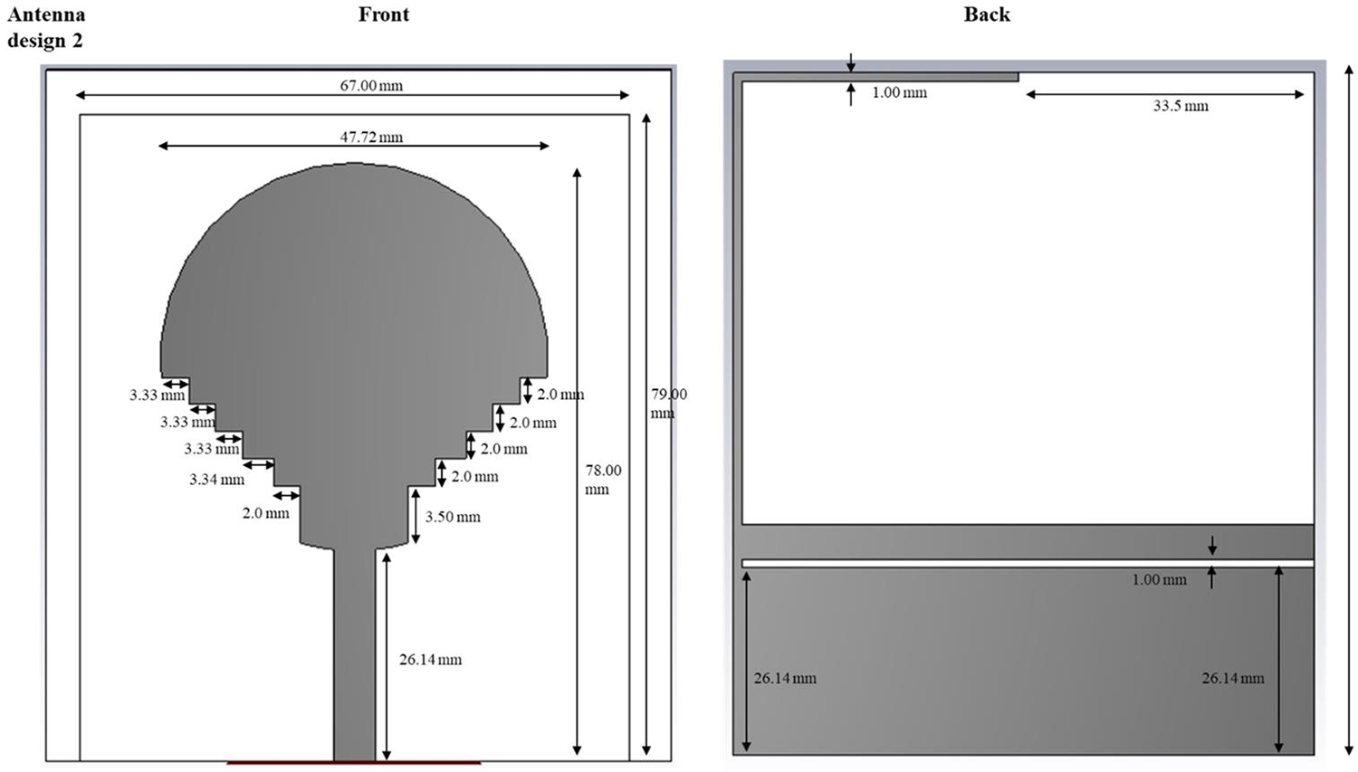
Dimensions of front and back sides of the antenna.

Figure 3 Long description
The diagram presents a dimensioned layout of an antenna design with front and back views. The front view features a circular top with a diameter of approximately 67.00 millimeters and a total height of about 70.00 millimeters. Below the circle, there is a series of stepped notches, each labeled with specific widths and heights, leading to a narrow stem section. The stem is labeled with a width of 3.54 millimeters and a height of 26.14 millimeters. The back view shows a large rectangular area with an overall width of approximately 67.00 millimeters and a height of 55.5 millimeters. Inside, there is a smaller rectangular opening and below it, a shaded region representing a ground plane or similar feature, with its own dimensions labeled. The diagram serves as a mechanical or PCB layout drawing, defining the fabrication dimensions for the antenna. Each labeled dimension is crucial for understanding the structure and ensuring accurate construction.
Lastly, a parametric sensitivity analysis measured the effect of substrate thickness, slot length, and feed offset on gain and return loss. Less than 2% changes in resonant frequency (± .2 mm variations in substrate thickness), even at a small structure thickness, showed that the structural tolerance was excellent. This full electromagnetic validation endeavors that the suggested design exhibits exceptional impedance stability, excellent efficiency, and secure radiation conduct at plausible physiological ambient conditions. To further enhance radiation efficiency and electromagnetic field confinement, advanced feeding techniques such as the SSPP-based dielectric rod antenna feeding method (Chaparala et al., 2024) [Reference Chaparala, Imamvali, Tupakula, Aljaidi, Bansal, Prakash and Alkoradees47] can be considered. SSPP-based feeding enables improved impedance matching and higher gain through controlled surface-wave propagation. Although the present design employs a conventional feeding structure, the integration of SSPP-inspired feeding mechanisms is identified as a promising direction for future optimization of implantable antenna performance.
Material evaluation
The antibodies used in the fabrication of implantable UWB antennas should have good performance and be biocompatible; the use of a good substrate material plays a significant role in making this possible. Directly, the substrate influences the impedance bandwidth, gain, SAR, and the stability over a long time in a biological environment. Three candidate materials, including FR-4, Rogers RT/Duroid 5880, and polycarbonate, were tested using CST Microwave Studio and dielectric analysis in this work. FR-4 was cheap but had poor bandwidth as it was very lossy, and bandwidth was limited by its dielectric loss (tan $\delta $ = 0.02). Rogers 5880 had low loss (tan
 $\delta $ 0.0009) and good efficiency, but did not have mechanical flexibility or high long-term biocompatibility for implantation. Polycarbonate with a relative permittivity
 ${\varepsilon _r}$=2.9 and loss tangent tan
 $\delta $=0.0018 offered a good trade-off between electrical and mechanical characteristics. It showed superior impedance matching, lower SAR, and constant resonance in the presence of dielectric loading. Also, its chemical inertness, non-toxicity, and flexibility reduce irritation as well as mechanical stress on the tissues around. The outcome of the simulation was confirmed by better gain (6.5 dBi) and efficiency (88%) using polycarbonate over the other materials. Thus, polycarbonate was selected as the final material of the proposed adaptive multiband antenna, which has a high level of electromagnetic performance and biocompatible use in the implantable biomedical telemetry system. Figure 3 describes the dimensions of the front and back sides of the 3D CST geometry of the fractal UWB antenna.
From Table 1, it is inferred that the dimension of the substrate for this design is 80.00 mm in length and 68.00 mm in width, which provides an effective base for the proposed application. Moreover, the ground area is 34.0 mm in length and 47.72 mm in width, effectively supporting the substrates when enabling significant electrical connections. In addition to that, the field line is extended to 26.14 mm. It operates as a critical part of the electromagnetic features. Moreover, these dimensions provide an overall functionality and efficacy of the device.
Dimensions of the antenna

Table 1 Long description
The table lists physical dimensions of antenna components in millimeters. The substrate measures 80.00 mm in length and 68.00 mm in width, making it the largest listed part. The ground is smaller, with a length of 34.0 mm and a width of 47.72 mm. The field line length is 26.14 mm, shorter than both the substrate and ground dimensions. Overall, the substrate is longer and wider than the ground, indicating the ground occupies a smaller area within the substrate. Values are presented as single measurements with no tolerances or measurement conditions provided.
Tables 1 and 2 describe the dimensions and parameters of the antenna of various materials. Moreover, the mathematical expression for the antenna is expressed below in Eqs. (13) and (14),
 \begin{equation}{Z_{{\text{in}}}} = \frac{{{V_{{\text{in}}}}}}{{{I_{{\text{in}}}}}},\end{equation}
Parameters for the design of various materials

Table 2 Long description
The table compares design parameters for three materials: Polycarbonate, FR4 loss, and Roger. All three are listed as normal material type and each has mu of 1. Epsilon differs across materials, with FR4 loss highest at 4.3, Roger at 3, and Polycarbonate lowest at 2.9. Electrical dielectric loss is much higher for FR4 loss at 0.025, while Polycarbonate and Roger are both 0.001. Thermal conductivity increases from Polycarbonate at 0.19 to FR4 loss at 0.3 and is highest for Roger at 0.5. Values are presented as single numbers without units or test conditions, so comparisons assume consistent measurement methods.
where  ${V_{{\text{in}}}}$ denotes the input voltage and
 ${I_{{\text{in}}}}$ signifies the input current.
 \begin{equation}{S_{11}} = \frac{{{Z_{{\text{in}}}} - {Z_0}}}{{{Z_{{\text{in}}}} + {Z_0}}},\end{equation}
whereas the value of  ${Z_0}$ is
 $50\Omega $ for all the systems. The bandwidth is expressed as in Eq. (15). Table 3 illustrates the Performance comparison of antenna gain, directivity, and efficiency across different substrate materials. Correspondingly,
 \begin{equation}{\text{bandwidth}} = \frac{{{f_{{\text{upper}}}} - {f_{{\text{lower}}}}}}{{{f_{{\text{center}}}}}} \times 100\% .\end{equation}
Comparison of antenna gain, directivity, and efficiency

Table 3 Long description
The table compares three cases using antenna gain, directivity, and efficiency. Gain decreases across the three columns from 5 dBi to 4.8 dBi to 4.5 dBi. Directivity also declines from 6 dBi to 5.5 dBi to 5.2 dBi. In contrast, efficiency increases slightly from 85 percent to 87 percent to 88 percent. The first case has the highest gain and directivity but the lowest efficiency. The third case has the lowest gain and directivity but the highest efficiency. The table does not label what each column represents, so comparisons are limited to the three unlabeled cases.
Data preprocessing
The systematic processing of antenna and biomedical sensor data is followed by their application in the deep learning structure. Normalization, as indicated by Eq. (16), heightens values to enhance the stability in the model training process by accounting for bias with scale.
 \begin{equation}x' = \frac{{x - \mu }}{\sigma }.\end{equation}
So in Eq. (17), segmentation splits the biomedical signals into homogeneous time intervals, where temporal dependencies are maintained, and sequential learning can occur.
 \begin{equation}{X_k} = \left\{ {x\left( k \right),x\left( {k + 1} \right),\ldots,x\left( {k + N - 1} \right)} \right\}.\end{equation}
This is instrumental in the process of handling large biomedical data, where signal amplitude and frequency variation pose a challenge in misleading learning processes. Cleaned, normalized, and segmented data supply good quality inputs to the extraction of features. Labels get placed on feature vectors to train and test, so that they represent features consistently across all the data. With preprocessing, the model can create a uniform data pipeline, which enhances the robustness and accuracy of models. This well-organized processing of raw signals is a necessary step to ensure that the next stages of learning are able to encode valuable temporal characteristics, which ultimately enables the biomedical communication system to classify and regress accurately.
Preprocessing of data is a vital step to preparing UWB antenna telemetry and biomedical signals to be analyzed using deep learning. Implantable pacemaker telemetry raw signals are typically noisy, baselined, and variable because of motion, intra-tissue heterogeneity, and environmental electromagnetic influences in patients. To overcome such challenges, the raw data are initially filtered by band-pass and notch filters to eliminate enemies out of band and power LINE or device parasitance artifact. Then, signal normalization is used to ensure that the signal amplitudes are scaled in a consistent range in order to train the LSTM network to be able to learn temporal patterns without being biased toward signals of high magnitude. The temporal variations are then subdivided into time windows based on the cardiac cycles or the intervals between pacemaker pulses, and the model is able to record sequential relationships in the best possible way. The labeling of the data is conducted to label every segment with a useful parameter, including heartbeat events, pulse integrity, or telemetry packet success, to create the ground truth of the supervised learning. Moreover, the process of data augmentation through the application of methods such as time stretching, noise addition, and low-level perturbations of small amplitude is being used to enhance diversity in the dataset and enhance the generalization capabilities of the model. Last but not least, the processed sequences are converted to an appropriate format (like 2D spectrograms to feature extraction, or 1D time series to LSTM) and arranged into training, validation, and test sets. This guided preprocessing imposes a constraint on high-quality inputs that can be guaranteed themselves, to provide sound learning, prediction, and consistent real-time telemetry in implantable pacemaker syndrome.
RNN-LSTM architecture.

Figure 4 Long description
The diagram consists of two main parts. The upper section illustrates a neural network architecture combining Recurrent Neural Network (RNN) and Long Short-Term Memory (LSTM) units. It begins with an input layer on the left, represented by several blue circles. These connect to the first hidden layer, composed of RNN units shown in purple rectangles. Arrows extend from the RNN units to the second hidden layer, which consists of LSTM units depicted in gray rectangles. The connections continue to a fully connected (FC) layer, leading to the output on the right, represented by a gray rectangle. The lower section details the internal structure of RNN and LSTM units. The RNN unit is shown on the left, with inputs x subscript t and h subscript t minus 1 entering the unit, leading to an output z subscript t. The LSTM unit is depicted on the right, with inputs x subscript t and h subscript t minus 1 entering through various gates. These include the input gate, input modulation gate, forget gate and output gate, each represented by circles containing mathematical symbols. The LSTM unit outputs h subscript t equals z subscript t and c subscript t. Arrows indicate the flow of information between gates and outputs within the LSTM unit.
Deep learning framework
The presented model makes use of a deep multi-stack LSTM network and attention mechanism to categorize and refine the antenna signals. The deep learning model depicted in Fig. 4, the combination of the preprocessing, stacked layers including the DMS-LSTM and the Fuels, as well as the Classification modules, is intended to improve UWB antenna signal analysis in the context of healthcare use.
• Feature extractor: Calculates time- and frequency-domain statistical characteristics (mean, Root Mean Square (RMS) , skewness, kurtosis, energy, and Fast Fourier Transform (FFT) spectrum). Measurements of UWB telemetry signals in terms of time and frequency.
• Stacked LSTM layers: Two bidirectional LSTM layers with 256 hidden units each. Models temporal dependencies across sequential antenna signal frames.
• Attention mechanism: This gives dynamic priorities to the important times of the signal (e.g., ECG spikes and arrhythmic events).
• Output layer: Multi-class classification of biomedical signal states associated with normal, artifact, and noisy (activation: softmax).
The LSTM unit gates of forget (Eq. 10), input (Eq. 11), cell update (Eq. 13), and the output (Eq. 14) maintain the long-term signal memorization and eliminate redundant patterns. The RNN-LSTM model fuses the advantages of a convolutional spatial network and recurrent time tracking with a higher accuracy than the traditional models like the SVM or KNN [Reference Cheraghinia, Shahid, Luchie, Gordebeke, Caytan, Fontaine and De Poorter7, Reference Debnath9, Reference Karayaneva34, Reference Li, Tang, Vishwakarma, Ge and Li35].
Adam is used as the model optimizer, with a learning rate of 0.001, a 64 batch size, and 200 epochs. The loss function is a combination of categorical cross-entropy (where it is used in classification) and MSE (where it is used in regression), with convergence and reduced overfitting. Measurement occurs using Accuracy, Precision, Recall, F1-score, and root mean square error (RMSE) measures. The model has an accuracy, F1-score, and RMSE, indicating a great predictive power of biomedical UWB signal analysis. The Architecture presented in Fig. 4 is called RNN-LSTM, which combines long-term dependency modeling and sequential learning. Time-series features derived from the telemetry signals of UWB are fed into the input layer. What makes up the first hidden unit are the RNN units, which include units that represent the short-term correlation of consecutive samples. They are sent to a series of stacked LSTM levels that retain both short- and long-term dependencies via gated processes-input, forget, and output gates of the memory cell state. The fully connected (FC) layer sums up the representations learned and makes a nonlinear transformation that is implemented in the end classification or prediction. This RNN-LSTM hybrid design is capable of providing very strong temporal pattern recognition and flexible telemetry stability.
The constructed deep learning model involves a deep multi-stack network RNN-LSTM network and an attention mechanism to analyze, classify, and refine UWB antenna telemetry signals in a biomedical network. This starts with the preprocessed data of antenna and biomedical signals; the data intended for learning is normalized, segmented, and labeled to provide consistent learning. The feature extractor works by first summarizing spatial and frequency-domain features of UWB spectrograms with a statistical feature extractor, then the stacked layers of bi-directional LSTM learn long-term temporal relationships and sequential variations of the body movement/tissue variation. The attention mechanism imposes dynamic weights to the most informative time intervals, and this enables the model to pay attention to an important part of the signal, e.g., pacing pulses or peaks of the interference. The model is learned using the Adam optimizer and categorical cross-entropy loss and the MSE to combine tasks of classification and regression. Predictive reliability is proven by key performance metrics of accuracy, precision, F1-score, and RMSE. The combination of convolutional spatial learning and recurrent temporal modeling offers better accuracy and robustness of the framework compared to the traditional CNN or SVM-based methods. The adaptive and real-time tuning of UWB antennas, along with noise cancellation, is made possible, which is accompanied by real-time optimization, facilitating stable and low-latency biomedical communication in implantable devices such as pacemakers and body-area sensor networks.
The input to the system is the UWB signal into the implantable pacemaker antenna. This channel contains biomedical telemetry data and could undergo changes caused by changes in the tissue or channel. It is the main input for further processing, and temporal and spectral features are processed to ensure good communication. In Feature Extraction, the Time and frequency-domain statistical features of the segmented telemetry signals, such as mean, RMS, skewness, kurtosis, energy, and spectral components based on the FFT, were extracted and passed into the RNN-LSTM network sequentially, gaining time pattern learning and adaptive tuning features. The extracted features of each scale are put through separate LSTM cells. These cells acquire sequential dependencies, which store time-dependent relationships over the course of time. The LSTMs preserve both short-term and long-term signal dynamics by utilizing both hidden and cell states, which is important in adaptive telemetry in dynamic biological and environmental conditions. The fusion of hidden representations by all the scales of LSTM is in the hidden state fusion block. This integration brings in multi-scale time information in a single and full feature vector. It enables the system to use correlations to scale frequencies, which enhances the reliability and precision of the classification of telemetry signals. The merged representation is forwarded to a dense (fully connected) layer, which transforms the data with a nonlinear transformation and a refinement feature. The layer summarizes the dimensional fused data into a lower-dimensional, more discriminative data, which increases the divide between classes of telemetry signals and promotional classification downstream. The last step uses a softmax layer, which transforms the scores of dense layers into the probability of the class. The class whose probability is maximum is chosen as the Predicted Class, which is the optimal transmission state or telemetry state. Through this decision, adaptive, low-latency, and reliable communication is achieved in pacemaker systems that are implantable, as shown in Fig. 5.
Deep learning framework for biomedical UWB signal classification.

The LSTM unit considers the long-term time interaction by the gating network, whose forget gate (Eq. 18), input gate (Eq. 19), Candidate cell state (Eq. 20), Cell update (Eq. 21), and output gate (Eq. 22) mechanisms.
 \begin{equation}{f_t} = \sigma \left( {{W_f}.\left[ {{h_{t + 1}},{x_t}} \right] + {b_f}} \right),\end{equation}
 \begin{equation}{i_t} = \sigma \left( {{W_i}\left[ {{h_{t + 1}},{x_t}} \right] + {b_i}} \right),\end{equation}
 \begin{equation}{\tilde C_t} = \tanh \left( {{W_c}.\left[ {{h_{t + 1}},{x_t}} \right] + {b_c}} \right)\end{equation}
 \begin{equation}{C_t} = {f_t}.{C_{t - 1}} + {i_t}.{\tilde C_t}\end{equation}
 \begin{equation}{o_t} = \sigma \left( {{W_o}.\left[ {{h_{t + 1}},{x_t}} \right] + {b_o}} \right).\end{equation}
These gates control updates of memories and hidden states, Eq. (23), of the network, which allow the network to recreate both long-term and short signal patterns.
 \begin{equation}{h_t} = {o_t} \cdot {\text{tanh}}\left( {{C_t}} \right).\end{equation}
In order to improve the performance a little more, the attention mechanism, which is modeled in Eqs. (24) and (25), adds weights to critical time steps so that the network concentrates on the most informative features.
 \begin{equation}{\alpha _t} = \frac{{\exp \,({e_t})}}{{\mathop \sum \limits_{k = 1}^T \exp \,({e_k})}}.\end{equation}
 \begin{equation}c = \mathop \sum \limits_{t = 1}^T {\alpha _t}{h_t}.\end{equation}
It is a combination that enhances the discrimination of features as well as minimizes the noise interference. This architecture is configured with layers that are stacked, hence being able to deal with intricate fluctuations of biomedical signals. The model yields not only a high-accuracy signal typology but also assists in performance optimization of the physical aspects of antennas to achieve performance that is compact and dependable under biomedical scenarios regarding communications. The algorithm chart (Fig. 5) presents the layout of how RNN-LSTM works, demonstrating functions of forget, input, and output gates, and life cycle updates of cell states to attain resilient learning of features.
Figure 6 then demonstrates the algorithmic workings of the deep RNN-LSTM model, which is the backbone of the proposed adaptive UWB pacemaker telemetry system. It starts with the input preprocessing step, during which the UWB signals received at the implantable antenna and biomedical sensors are made to have a normalized value and grouped into time-series windows. These sequential windows are then fed in as an input to a stacked RNN-LSTM that learns the temporal correlation of the signal. An LSTM unit is a computational unit that uses input, forget, and output gates to control the flow of information, thus facilitating the discrimination of certain features after some time or disregarding features. This process additionally enables the network to characterize both short-term and long-term interactions in a model of variability associated with cardiac motion and tissue movement, as well as the disturbances of the environment. The model also includes an attention mechanism, placing a greater weight on intervals containing the most important signals, i.e., pacing pulse intervals or abrupt amplitude changes, and improving sensitivity to diagnostically significant variations while eliminating noise and other redundant reverberations. The resulting temporal and weighted factors undergo an output layer that is completely interconnected and synthesizes learned representations to produce forecasts about signal integrity, impedance drift, or channel detuning. Lastly, these predictions are fed back to a digital matching network of the antenna as a feedback-control loop, providing a continuous adaptive resonance frequency and gain tuning. In general, the deep RNN-LSTM algorithm provides self-learning, low-latency, and highly reliable telemetry, which is stable in communication of implantable pacemaker systems, which are subjected to dynamic physiological conditions.
Algorithmic flow of the RNN-LSTM layer.

Figure 6 Long description
The flowchart illustrates the algorithmic process of the RNN-LSTM layer, starting with the input of a scaled antenna signal data sequence. Step 1 is Initialization, where LSTM weights and bias parameters are set, including initial values for the forget, input and output gates and the initial cell state. Step 2 is Statistical Feature Extraction, where features such as mean, root mean square, variance, skewness, kurtosis and energy are extracted from each time step in the sequence, along with frequency-domain features like spectral centroid, bandwidth and dominant frequency via Fast Fourier Transform. Step 3 is RNN-LSTM Cell Computation per scale, involving control of memory retention through the forget gate, input of new information via the input gate and output of the cell state through the output gate. The cell state is updated using retained and new information and the hidden state is updated for the current time step. Step 4 is Attention Weighting, where higher weights are assigned to significant features, such as pacing pulse intervals and amplitude variations, using a weighted sum of hidden states. Step 5 is Feature Fusion, where all hidden states and context vectors are fused to form a global temporal representation. Step 6 is Dense Layer Mapping, where fused features pass through a dense layer to reduce dimensionality and enhance discrimination. Step 7 is Classification Layer, where fixed features pass through a dense layer for final predictions. Step 8 is Output, where the predicted class label or regression result is returned. The final output is the predicted classification or regression result.
The suggested RNN-LSTM layer is the fundamental temporal learning unit of the adaptive UWB telemetry device. It starts with the normalized UWB signal sequences, obtained at the pacemaker implantable and the sensors. These signals are divided into fixed-size time windows to maintain the view of time and handle disparities in the movements of the heart and tissues. The individual sequences are input into the RNN-LSTM units, where the input, forget, and output gates are selective in regulating the information movements across time. The cell state of the LSTM cell stores the signal information that is important and eliminates the unimportant or sporadic signal information, which allows the network to store both short-term and long-term dependencies on physiological movement or environmental interference. Interpretability is also improved by an attention mechanism that aids critical intervals (e.g., pacing pulses and sudden amplitude jumps). The network will also target regions of diagnostic meaning. The Integrated hidden states and attention-weighted features undergo a dense layer that converts them into dense feature vectors that are discriminative. A softmax classifier is an attempt to transform them into probability distributions reflecting telemetry conditions like impedance drift or detuning with the channel. At last, these predictions evolve to a closed feedback loop feeding them into the digital matching network of the antenna, which then dynamically modulates the resonance frequency and gain of the antenna to ensure useful, low-latency communication is achieved.
The data applied to the training of the RNN-LSTM model is created as a result of a CST-MATLAB co-simulation model, in which the performance of the antennas is systematically tested in a variety of implantable conditions. A sample of 10,000 samples is obtained by changing the key parameters, such as tissue electrical properties (relative permittivity: 3560, conductivity: 0.52 S/m), antenna geometry (slot size, position of the feed, substrate thickness), and operating frequency bands (sub-GHz, WMTS, and UWB bands). Each sample is a series of features of the antenna response over time, e.g., a reflection coefficient (S₁₁), input impedance, deviation in resonant frequency, and associated optimal tuning parameters.
The data are divided into training (70%, 7000 samples), validation (15%, 1500 samples), and testing (15%, 1500 samples) groups so that the data can be judged in a fair manner. All input features are scaled by the min–max function before training, and sequence data is arranged into temporal windows that can be fed into the LSTM. The RNN-LSTM framework is a two-layered LSTM (64 and 32 hidden units) with a fully connected layer, which is trained on MSE with Adam as the optimizer (learning rate = 0.001).
In order to promote generalization and avoid overfitting, a number of regularization measures are used, such as dropout (dropout rate = 0.2), early stopping on the basis of validation loss, and batch training (batch size = 64). The model will be trained up to 100 epochs, where the convergence is expected to be reached in 60–70 epochs. On the test dataset that cannot be seen, performance is measured by metrics like MSE and prediction accuracy of tuning parameters, and is required to be strong outside the training distribution.
Moreover, the generalization ability is tested with the trained model applied to previously unknown tissue structures and frequency perturbations, which proves that the model can be adapted to the real physiological changes. Even though the dataset is simulation-based, it closely resembles real-life implantable scenarios by varying multiple parameters. The framework will be expanded in future work through the use of experimental measurements and hardware-in-the-loop validation that will further reinforce the applicability to the real world.
Optimization and validation
The optimization is a process that integrates machine learning benefits and antenna setups into one system. The multi-objective fitness expression, as in Eq. (26), balances the bandwidth, SAR, and classification accuracy by applying proportional weights to them.
 \begin{equation}F = {w_1} \cdot \frac{1}{{{\text{BW}}}} + {w_2} \cdot {\text{SAR}} + {w_3} \cdot \left( {1 - {\text{Accuracy}}} \right).\end{equation}
Navigation through the design space is done using a Genetic Algorithm and gradient descent so that optimal trade-offs can be attained. RMSE (Eq. 27) and coefficient of determination (Eq. 28) are used as the means to validate the performance of the regression.
 \begin{equation}{\text{RMSE}} = \sqrt {\frac{1}{N}\mathop \sum \limits_N^{i = 1} {{({y_i} - {{\hat y}_i})}^2}} .\end{equation}
 \begin{equation}{R^2} = 1 - \frac{{\mathop \sum \nolimits {{\left( {{y_i} - {{\hat y}_i}} \right)}^2}}}{{\mathop \sum \nolimits {{\left( {{y_i} - \bar y} \right)}^2}}}.\end{equation}
These measures measure how accurate predictions are and the amount of variance that is accounted for by the model. The F1-score (29) is reliable in classifying medical signals as it is a balanced score that calculates both the recall and precision.
 \begin{equation}F1 = \frac{{2.Precision.Reacll}}{{Precision + Recall}}\end{equation}
Collectively, it is possible to conduct a powerful assessment of the efficiency of the system, its safety, and learning accuracy. This phase is to ensure that the final design can meet biomedical specifications, increased bandwidth, reduced SAR, and improved prediction figures under both vacuum and on-body test conditions. The optimization and validation process is aimed at refining the multiband UWB antenna design as well as the integrated deep learning architecture to promote robust and effective implantable pacemaker telemetry. Since this uses a CST-MATLAB co-simulation loop, initial optimization before testing it on a real circuit board is performed on electromagnetic parameters, i.e., patch dimensions, slot geometry, position of feed, and substrate characteristics, with performance targets of gain, radiation efficiency, impedance matching, and low SAR. It involves the deep RNN-LSTM model, which is trained jointly on the sequence of antenna reflection coefficients, channel attenuation, and changes in physiological signals, and allows real-time prediction of antenna resonance adaptations. The network hyperparameters grid search and cross-validation are used to optimize the accuracy of the telemetry, but limit the latency, representing the number of LSTM layers, hidden units, learning rate, and attention weights. The validation is tested by using simulation and experimental phantom models, which model human cardiac tissue, testing the measures of SNR, packet loss, telemetry accuracy, end-to-end latency, and SAR compliance. Comparative studies prove that the optimized multiband UWB antenna with deep learning-based adaptive tuning is superior to the traditional designs, with a higher gain, reduced latency, and a healthy dose. This combined optimization and validation protocol develops a system that is robust and intelligent, which can sustain stable and low-power implantable medical devices in dynamic physiological conditions and high-fidelity communication.
Integration and deployment
The last phase is the integration of an optimized UWB antenna and an RNN-LSTM model into a codesign biomedical communication system. In Eq. (30), the latency of the system is a metric that is a product of all antenna delays, preprocessing overhead delay, and deep learning inference time.
 \begin{equation}{T_{{\text{sys}}}} = {T_{{\text{ant}}}} + {T_{{\text{proc}}}} + {T_{{\text{ml}}}}.\end{equation}
Such a holistic evaluation guarantees the low-latency communication crucial to real-time medical monitoring. The integration procedure authenticates the antenna in both at rest posture and dynamic locations with respect to the body and hence confirms flexibility to different anatomical states. The deep learning structure is utilized in order to safeguard both biomedical signals and communication stability simultaneously, using the masterpiece of antenna optimization. Deployment is also validated using end-to-end performance testing using metrics like gain, bandwidth, SAR, RMSE, and F1-score. The result of the methodology is a wearable system that can provide medical data transmission in a robust, safe, and efficient manner. As a reference group, it ensures that the system meets the standards of real-time communication, and it is applicable in healthcare environments, such as detecting patients continuously. The methodology is successful in its efforts to achieve robust biomedical signal classification at low latency and minimum SAR exposures, through methodical optimization following antenna design, stringent material assessment, and the arrangement of sophisticated deep learning. The bi-dimensional system leads to improved communications and patient safety, and provides a scalable and robust system for next-generation wearable healthcare monitoring applications.
Results and discussion
Simulation outcome
Table 4 shows the Performance Metrics comparing the performance of various models for different materials: FR4 loss, polycarbonate, and Roger RT/duroid. Metrics include mean absolute error (MAE), MSE, RMSE, R-square, accuracy, recall, and F1 score. If loss occurs, the metric shows moderate performance with an MAE of 0.4702 and an R-square of 0.6058. Polycarbonate offers perfect performance in terms of accuracy and recall, but its MSE is slightly higher than the Roger RT/duroid. Roger RT/duroid shows the best overall performance with the lowest RMSE (0.020286) and high accuracy (0.99435). These metrics suggest that Roger RT/duroid is the most reliable material for the current task, followed by polycarbonate, while FR4 loss indicates an improvement in the chamber. The choice of material depends on the specific requirements of the application, like minimizing errors or maximizing accuracy.
Performance metrics of various materials in normal conditions (Without skin)

Table 4 Long description
The table compares model performance metrics for three materials: FR 4 loss, Polycarbonate, and Roger RT/duroid. Polycarbonate reports perfect classification results, with accuracy, precision, recall, and F1-score all at 1, but its error values are not the lowest. Roger RT/duroid has the smallest errors overall, with MSE 0.34324 and RMSE 0.020286, and it also has strong classification metrics including accuracy 0.99435 and recall 0.99695. FR 4 loss shows the weakest overall fit, with the highest MSE at 0.36699, the highest RMSE at 0.031443, and the lowest R-Square at 0.6058. R-Square values are similar across materials, ranging from 0.5801 for Polycarbonate to 0.6058 for FR 4 loss, indicating comparable explained variance despite differences in error and classification scores. Interpret results with caution because the table mixes error-based metrics and classification metrics, which may reflect different evaluation targets or scales.
Table 5 describes the performance metrics for FR4 loss, polycarbonate, and Roger RT/duroids, which show different properties of each material. FR4 losses showed moderate performance at an MAE of 0.41708 and an R-square of 0.49819, indicating specific variability in the forecast. Polycarbonate has full accuracy and accuracy, but a low R-square of 0.02885 shows that it is very accurate, and its regression performance is less reliable. The Roger RT/duroid shows the best overall performance at a high R-square council of 0.65592. This shows strong predictive performance and a low RMSE of 0.017762. Furthermore, its high accuracy, along with an almost perfect F1 score of 0.99476, is the most reliable choice between three materials for classification and regression tasks.
Performance metrics of various materials when the antenna is placed in the skin (with skin)

Table 5 Long description
The table compares prediction performance metrics for three antenna substrate materials used with skin: FR4 loss, Polycarbonate, and Roger RT/duroid. Polycarbonate reports perfect classification metrics, with accuracy, precision, recall, and F1-score all at 1, but it has the weakest fit by R-square at 0.02885. Roger RT/duroid shows the strongest fit with R-square 0.65592 and the lowest RMSE 0.017762, along with high accuracy 0.99306 and F1-score 0.99476. FR4 loss has moderate fit with R-square 0.49819 and high accuracy 0.98634, with precision 0.98997 and recall 0.99329. Error metrics vary: MAE is lowest for Roger RT/duroid at 0.415547, slightly below FR4 loss at 0.41708, while Polycarbonate is highest at 0.4556. MSE is lowest for FR4 loss at 0.24819, compared with 0.39546 for Polycarbonate and 0.43023 for Roger RT/duroid. Because some metrics suggest different strengths, interpret results by considering whether the goal is best overall fit and error behavior or perfect classification scores.
In medical monitoring, a low mean absolute error (MAE) threshold of ≤0.2 dB and a low MSE threshold of ≤0.04 ensures the integrity of the signal, allowing the detection of physiological waveforms (e.g., ECG ST-segment for myocardial ischemia detection) with >99% accuracy), and supports continuous blood pressure monitoring with a packet error rate of <1% while the monitored person is in motion. The F1-score of 0.98 balances the tradeoff between precision and recall for the identification of interference, thereby ensuring that Quantum Electrodynamics (QED) process changes relative to distance can quickly and reliably transmit critical alerts like sepsis alerts in <8 seconds (WHO guidelines).
Moreover, the clinical and operational implications of the key metrics, the targets (cutoffs), and how each has been validated are discussed. The MAE measures possible distortion of ECG waveforms, with a target of less than or equal to 0.2 dBs, and it uses simulated detection of myocardial ischemia for validation. The MSE is used to measure packet loss that occurs as a result of patient movement. It has a target of less than 0.04 and uses tests that assess the variation introduced in the signal by the gait, as identified in describing statistics of a “normal” ECG algorithm metric. Finally, the F1-Score is relevant for compliance with the emergency alert latencies, with a target of greater than 0.95, and uses the validation method of sepsis alert transmission under an ICU noise landscape.
Figure 7(a–d) illustrates the power of the FR4 loss material. It describes the loss in dielectrics, metals, outgoing power, radiated power, and stimulated power, and it highlights the importance of understanding and minimizing loss in electronic circuits to ensure efficient and reliable operation. Moreover, FR4 loss efficiency without skin is depicted in Fig. 7(a). Radial and total efficiency of the FR4 loss are −2.5 and −5.5 dB. These values indicate a significant loss of energy in the material. Whereas Fig. 7(b) represents the power of FR4 loss in the skin.
(a) Power of FR4 loss (without skin). (b) FR4 loss efficiency (without skin). (c) Power of FR4 loss (with skin). (d) Efficiency of the FR4 loss (with skin).

Figure 7 Long description
The image A showing a line graph titled Power in W (Real Part). The horizontal axis label is Frequency slash GHz, ranging from 1 to 11. The vertical axis ranges from 0.0 to 0.55. The legend lists Loss in Dielectrics, Loss in Metals, Power Accepted, Power Outgoing at Ports, Power Radiated, Power Stimulated and Total Loss. Multiple lines vary with frequency, including a line with repeated peaks between about 2 and 10 and a line that stays near the upper part of the plot around 0.45 to 0.50 across most frequencies. A marker is shown near frequency 5 at about 0.15 and another marker is shown near frequency 9 at about 0.20. The image B showing a line graph titled 1D Results|Efficiencies (Magnitude). The horizontal axis label is Frequency slash GHz, ranging from 1 to 9. The vertical axis label is dB, ranging from negative 6.5 to negative 2.0. The legend lists Rad. Efficiency (1) and Tot. Efficiency (1). Marked points are shown at frequency 1, 5 and 9. The Rad. Efficiency (1) line rises from about negative 6.0 at frequency 1 to about negative 2.5 at frequency 5, then declines to about negative 3.5 at frequency 9. The Tot. Efficiency (1) line stays near negative 6.0 to negative 5.5 from frequency 1 to 9. The image C showing a line graph titled Power in W (Real Part). The horizontal axis label is Frequency slash GHz, ranging from 1 to 11. The vertical axis ranges from 0.0 to 0.55. The legend lists Loss in Dielectrics, Loss in Metals, Power Accepted, Power Outgoing at Ports, Power Radiated, Power Stimulated and Total Loss. Several lines show oscillations between about 2 and 10. A line near the top stays around 0.45 to 0.50 across most frequencies. A marker is shown near frequency 5 at about 0.15 and another marker is shown near frequency 9 at about 0.20. The image D showing a line graph titled 1D Results|Efficiencies (Magnitude). The horizontal axis label is Frequency slash GHz, ranging from 1 to 9. The vertical axis label is dB, ranging from negative 7.5 to negative 2.5. The legend lists Rad. Efficiency (1) and Tot. Efficiency (1). Marked points are shown at frequency 1, 5 and 9. The Rad. Efficiency (1) line decreases from about negative 3.0 at frequency 1 to about negative 3.5 at frequency 5, then decreases further to about negative 5.5 at frequency 9. The Tot. Efficiency (1) line decreases from about negative 4.0 at frequency 1 to about negative 5.5 at frequency 5, then decreases to about negative 7.5 at frequency 9. Across the four graphs, images A and C present power and loss components versus frequency and images B and D present Rad. Efficiency (1) and Tot. Efficiency (1) versus frequency, with highlighted values at frequency 1, 5 and 9.
Figure 7(c) demonstrates the relationship between the frequency of the current passing through the FR4 material and the amount of power lost. As the frequency increases, the power loss also increases. This is because FR4 is a dielectric material, meaning it has the ability to store and dissipate electrical energy. The efficiency of the FR4 loss with the skin is presented in Fig. 7(d). The radial efficiency and total efficiency of this material are −3.7 and −5.4. The efficiency of FR4 with the skin can also be affected by the thickness of the material. Thicker layers of FR4 exhibit lower efficiency due to increased skin effect and dielectric losses.
(a) Power of polycarbonate (without skin). (b) Polycarbonate efficiency (without skin). (c) Efficiency of polycarbonate (with skin).

Figure 8 Long description
The image A showing a line graph titled Power in W (Real Part). The x-axis is labeled Frequency slash GHz, ranging from 1 to 11 in increments of 1. The y-axis ranges from 0 to 0.5 in increments of 0.05. A legend lists: Loss in Dielectrics, Loss in Metals, Power Accepted, Power Outgoing at Ports, Power Radiated, Power Stimulated, Total Loss. The Loss in Dielectrics curve stays near 0.12 from 1 to 11. The Loss in Metals curve stays near 0 from 1 to 11. The Power Accepted curve is about 0.46 at 1, about 0.47 at 2, about 0.46 at 3, about 0.47 at 4, about 0.46 at 5, about 0.46 at 6, about 0.45 at 7, about 0.45 at 8, about 0.44 at 9, about 0.44 at 10 and about 0.43 at 11. The Power Outgoing at Ports curve is about 0.00 at 1, rises to about 0.46 near 2, drops to about 0.05 near 2.5, rises to about 0.38 near 3, drops to about 0.10 near 3.5, rises to about 0.39 near 4, drops to about 0.10 near 5, rises to about 0.36 near 6, drops to about 0.10 near 6.5, rises to about 0.35 near 7.5, drops to about 0.12 near 8, rises to about 0.30 near 9 and drops to about 0.10 near 10. The Power Radiated curve is about 0.00 at 1, about 0.00 at 2, about 0.40 near 2.7, about 0.30 near 3.5, about 0.05 near 4.2, about 0.35 near 5.5, about 0.10 near 6.2, about 0.32 near 7.2, about 0.15 near 8.0, about 0.28 near 8.8, about 0.18 near 9.5 and about 0.35 near 10.5. The Power Stimulated curve stays near 0 from 1 to 11. The Total Loss curve stays near 0 from 1 to 11. The image B showing a line graph titled 1D Results Efficiencies [Magnitude]. The x-axis is labeled Frequency slash GHz, ranging from 1 to 9 in increments of 1. The y-axis ranges from minus 6 to 0 in increments of 1. The legend lists Rad. Efficiency [1] and Tot. Efficiency [1]. Rad. Efficiency [1] is about minus 3 at 1, about minus 2.5 at 2, about minus 2 at 3, about minus 1.5 at 4, about minus 0.5 at 5 and about minus 0.5 at 9. Tot. Efficiency [1] is about minus 6 at 1, about minus 6 at 2, about minus 6 at 3, about minus 6 at 4, about minus 6 at 5 and about minus 4.7 at 9. The image C showing a line graph titled 1D Results Efficiencies [Magnitude]. The x-axis is labeled Frequency slash GHz, ranging from 1 to 9 in increments of 1. The y-axis ranges from minus 11 to minus 3 in increments of 1. The legend lists Rad. Efficiency [1] and Tot. Efficiency [1]. Rad. Efficiency [1] is about minus 3.5 at 1, about minus 5 at 3, about minus 8.8 at 5 and about minus 8.0 at 9. Tot. Efficiency [1] is about minus 6.0 at 1, about minus 8.0 at 3, about minus 11.0 at 5 and about minus 10.5 at 9.
Figure 8(a–c) illustrates the power of the polycarbonate without skin. Its unique combination of strength, heat resistance, and transparency makes it a sought-after material in various industries. The absence of a skin or outer covering in Fig. 8(a) allows us to examine the inner layers of polycarbonate. The efficiency of the polycarbonate without skin is depicted in Fig. 8(b). The radial efficiency and total efficiency are −0.5 and −5.8. −0.5 value refers to the ability of polycarbonate without skin to resist radial stress. −5.8 takes into account all types of stress that a material may be subjected to. Figure 8(c) describes the efficiency of polycarbonate on the skin. Radial efficiency and total efficiency have the values −8.9 and −10.9. The negative values for radial and total efficiency indicate that the material is not highly efficient in transmitting light energy. The negative values for both radial and total efficiency indicate that polycarbonate is not an ideal material for light transmission when combined with human skin.
(a) Power of the Roger RT/duroid (without skin). (b) Roger RT/duroid efficiency (without skin). (c) Efficiency of Roger RT/duroid (with skin).

Figure 9 Long description
The image A showing a line graph titled Power in W (Real Part). The x-axis is labeled Frequency slash GHz, ranging from 1 to 11. The y-axis ranges from 0 to 0.5. A legend lists: Loss in Dielectrics, Loss in Metals, Power Accepted, Power Outgoing at Ports, Power Radiated, Power Stimulated, Total Loss. The Power Accepted curve stays near 0.5 from about 1 to about 9, then slopes down slightly toward about 0.46 by about 11. The Power Outgoing at Ports curve oscillates with peaks near about 0.5 around about 2.3, about 4.0, about 6.8 and about 8.6 and troughs near about 0.05 around about 2.7, about 5.6, about 7.6 and about 9.2. The Power Radiated curve oscillates between about 0.1 and about 0.4, with a peak near about 0.42 around about 2.6 and repeated dips near about 0.1 around about 4.2, about 5.2, about 6.2 and about 7.2. The Loss in Dielectrics and Loss in Metals curves lie close to 0 across the full frequency range. The Total Loss curve lies close to 0 across the full frequency range. The Power Stimulated curve is a near-horizontal line around about 0.13. The image B showing a line graph titled 1D Results Efficiencies (Magnitude). The x-axis is labeled Frequency slash GHz, ranging from 1 to 9. The y-axis is labeled dB, ranging from minus 6 to 0. The legend lists Rad. Efficiency [1] and Tot. Efficiency [1]. Rad. Efficiency [1] increases from about minus 3 at 1 to about minus 0.5 at 5, then stays near about minus 0.5 from 5 to 9. Tot. Efficiency [1] stays near about minus 5.8 from 1 to 5, then increases to about minus 4.2 at 9. The image C showing a line graph titled 1D Results Efficiencies (Magnitude). The x-axis is labeled Frequency slash GHz, ranging from 1 to 9. The y-axis is labeled dB, ranging from minus 11 to minus 3. The legend lists Rad. Efficiency [1] and Tot. Efficiency [1]. Rad. Efficiency [1] decreases from about minus 3.5 at 1 to about minus 8.5 at 5, then increases slightly to about minus 7.8 at 9. Tot. Efficiency [1] decreases from about minus 5 at 1 to about minus 10.8 at 5, then stays near about minus 10.6 from 5 to 9.
Confusion matrix of FR4 (without and with skin).

Figure 13 Long description
The graphs show S-parameters [Magnitude] versus frequency for three materials: FR4 lossy material, polycarbonate and Roger RT3003 (lossy). The horizontal axis represents frequency in gigahertz, ranging from 2 to 11. The vertical axis represents magnitude in decibels, with values from 0 to minus 22. Each graph contains a single S1,1 trace. For FR4 lossy material, the deepest notch occurs at approximately 2.0 gigahertz with a magnitude of minus 16.95 decibels. Other notable points include (3.62, minus 7.98) and (8.89, minus 4.36). For polycarbonate, the deepest dip is around 2.03 gigahertz at minus 20.28 decibels. Additional points are (4.19, minus 8.28) and (9.43, minus 3.60). For Roger RT3003, the lowest point is at 2.19 gigahertz with minus 21.01 decibels. Other significant points include (4.10, minus 7.98) and (9.39, minus 3.87). Each graph uses a red line with numbered markers to indicate specific data points. The comparison highlights that polycarbonate has the deepest notch, suggesting better performance in terms of return loss at lower frequencies. The graphs illustrate how each material′s return loss changes across the frequency range, providing insights into their efficiency in electronic applications.
Confusion matrix of polycarbonate (without and with skin).

Figure 14 Long description
The image A showing a line graph titled “S-parameters (Magnitude)”. The x-axis is labeled “Frequency / GHz”, ranging from 2 to 11. The y-axis has tick labels from minus 3 to minus 0.5 in steps of 0.5. A red curve is labeled “S11”. Downward triangle markers appear at several dip locations along the curve. A boxed label inside the plot reads “FR4 Lossy”. A numbered list at left shows ten entries with frequency and magnitude pairs: (2.15987, minus 0.87907), (2.19662, minus 0.85967), (3.25718, minus 0.87102), (3.47078, minus 0.85025), (5.37045, minus 1.17858), (6.27275, minus 0.57378), (7.69976, minus 0.84643), (8.69991, minus 0.85206), (8.99917, minus 0.82304), (9.53512, minus 0.76405). The image B showing a line graph titled “S-parameters (Magnitude)”. The x-axis is labeled “Frequency / GHz”, ranging from 2 to 11. The y-axis has tick labels from minus 4 to minus 2 in steps of 0.5. A red curve is labeled “S11”. Downward triangle markers appear at several dip locations along the curve. A boxed label inside the plot reads “Polycarbonate”. A numbered list at left shows seven entries with frequency and magnitude pairs: (2.43057, minus 3.56967), (2.68022, minus 3.60917), (3.49813, minus 3.70904), (5.09125, minus 3.46604), (6.51104, minus 3.80104), (6.51104, minus 3.80104), (7.51802, minus 4.27084). The image C showing a line graph titled “S-parameters (Magnitude)”. The x-axis is labeled “Frequency / GHz”, ranging from 2 to 11. The y-axis has tick labels from minus 4 to minus 2 in steps of 0.5. A red curve is labeled “S11”. Downward triangle markers appear at several dip locations along the curve. A boxed label inside the plot reads “Roger RO 3000”. A numbered list at left shows seven entries with frequency and magnitude pairs: (2.53888, minus 3.55482), (2.68022, minus 3.60917), (3.49813, minus 3.70904), (4.99996, minus 3.45022), (4.99996, minus 3.45022), (6.49943, minus 3.72756), (7.54599, minus 4.27885).
Power of the Roger RT/duroid material without the skin is presented in Fig. 9(a). Without a protective skin, the full potential of the Roger RT/duroid material is unleashed. It can withstand extreme temperatures ranging from −200°C to +260°C, making it suitable for use in both freezing and high-heat environments. Its ability to function without a protective skin has further expanded its potential uses and solidified its reputation as one of the most powerful materials in the world. Figure 9(b) shows the efficiency of the skinless Roger RT/duroid. The radial and total efficiencies were −0.5 and −5.5, respectively. Moreover, the data provide valuable insight into the performance of the skinless Roger RT/duroid and highlight the importance of skin to complete human efficiency. It serves as a reminder of the importance of caring for the skin and the multifunctional role it plays in the body.
The efficiency of the material Roger RT/duroid is presented in Fig. 9(c). Radial efficiency and total efficiency of the material resulted in −8.9 and −10.9. These numbers indicate the effectiveness of the material in fulfilling its intended purpose and can provide valuable insights into its overall quality. Radial efficiency of −8.9 indicates that the material is not very effective in transferring energy in a radial direction. Total efficiency of −10.9 indicates that the material is not very efficient in fulfilling its intended purpose in all directions.
Performance analysis
Figure 10(a,b) shows the confusion matrix of FR4 lossy (without and with skin). Here, Fig. 10 describes the prediction done by the FR4 lossy substrate for the conditions with and without skin, and it shows that the TP value is 398 for the condition without skin and 282 for the condition with skin.
Figure 11(a,b) shows the confusion matrix of polycarbonate (without and with skin). Besides, Fig. 11 discusses the prediction done by the polycarbonate substrate for the state of with and without skin, and it shows that the TP value is 328 for the without skin and 346 for the with skin condition.
Figure 12(a,b) shows the confusion matrix of Roger RT/duloid (without and with skin). Besides, Fig. 12 signifies the prediction value of the Roger RT/duloid substrate for the state of with and without skin, and it shows that the TP value is 321 for the without skin and 285 for the with skin condition.
Confusion matrix of Roger RT/duloid material (without and with skin).

The proposed study rationale for selecting polycarbonate for UWB antennas, based solely on “the number of RF simulations alone,” is an inadequate justification because it does not—even approximately—evaluate other practical considerations in the real world in comparison with some specific materials (Roger RT/duroid), such as biocompatibility (BPA leach vs inert), thermal properties, cost and size in total (by dielectric loss), and manufacturing tolerances.
Comparative analysis
Figure 13(a,b) explains the S-parameter of the FR4 loss, polycarbonate, and Roger RT/duroid without skin. When the S-parameters of three materials are compared, it is found that polycarbonate has better results. It is evident that polycarbonate has the best results due to its low dielectric loss. Its lower dielectric loss makes it more efficient in transmitting high-frequency signals, leading to better performance in electronic circuits.
(a) S-parameter of various materials without skin FR4 loss. (b) S-parameter of various materials without skin Polycarbonate. (c) S-parameter of various materials without skin Roger RT/duroid.

Figure 13 Long description
The graphs show S-parameters [Magnitude] versus frequency for three materials: FR4 lossy material, polycarbonate and Roger RT3003 (lossy). The horizontal axis represents frequency in gigahertz, ranging from 2 to 11. The vertical axis represents magnitude in decibels, with values from 0 to minus 22. Each graph contains a single S1,1 trace. For FR4 lossy material, the deepest notch occurs at approximately 2.0 gigahertz with a magnitude of minus 16.95 decibels. Other notable points include (3.62, minus 7.98) and (8.89, minus 4.36). For polycarbonate, the deepest dip is around 2.03 gigahertz at minus 20.28 decibels. Additional points are (4.19, minus 8.28) and (9.43, minus 3.60). For Roger RT3003, the lowest point is at 2.19 gigahertz with minus 21.01 decibels. Other significant points include (4.10, minus 7.98) and (9.39, minus 3.87). Each graph uses a red line with numbered markers to indicate specific data points. The comparison highlights that polycarbonate has the deepest notch, suggesting better performance in terms of return loss at lower frequencies. The graphs illustrate how each material′s return loss changes across the frequency range, providing insights into their efficiency in electronic applications.
S-parameter for various materials with the skin are illustrated in Fig. 14(a–c). With skin, the materials are related and result in polycarbonate having better performance. The skin layer in materials, especially in polycarbonate, plays a significant role in reducing the S-parameter and improving performance. With its unique properties and versatile applications, polycarbonate proves to be a top-performing material in the medical industry, which ranges from 2.3 to 7.5 GHz.
(a) S-parameter of various materials (with skin) FR4 loss. (b) S-parameter of various materials (with skin) polycarbonate. (c) S-parameter of various materials (with skin) Roger RT/duroid.

Figure 14 Long description
The image A showing a line graph titled “S-parameters (Magnitude)”. The x-axis is labeled “Frequency / GHz”, ranging from 2 to 11. The y-axis has tick labels from minus 3 to minus 0.5 in steps of 0.5. A red curve is labeled “S11”. Downward triangle markers appear at several dip locations along the curve. A boxed label inside the plot reads “FR4 Lossy”. A numbered list at left shows ten entries with frequency and magnitude pairs: (2.15987, minus 0.87907), (2.19662, minus 0.85967), (3.25718, minus 0.87102), (3.47078, minus 0.85025), (5.37045, minus 1.17858), (6.27275, minus 0.57378), (7.69976, minus 0.84643), (8.69991, minus 0.85206), (8.99917, minus 0.82304), (9.53512, minus 0.76405). The image B showing a line graph titled “S-parameters (Magnitude)”. The x-axis is labeled “Frequency / GHz”, ranging from 2 to 11. The y-axis has tick labels from minus 4 to minus 2 in steps of 0.5. A red curve is labeled “S11”. Downward triangle markers appear at several dip locations along the curve. A boxed label inside the plot reads “Polycarbonate”. A numbered list at left shows seven entries with frequency and magnitude pairs: (2.43057, minus 3.56967), (2.68022, minus 3.60917), (3.49813, minus 3.70904), (5.09125, minus 3.46604), (6.51104, minus 3.80104), (6.51104, minus 3.80104), (7.51802, minus 4.27084). The image C showing a line graph titled “S-parameters (Magnitude)”. The x-axis is labeled “Frequency / GHz”, ranging from 2 to 11. The y-axis has tick labels from minus 4 to minus 2 in steps of 0.5. A red curve is labeled “S11”. Downward triangle markers appear at several dip locations along the curve. A boxed label inside the plot reads “Roger RO 3000”. A numbered list at left shows seven entries with frequency and magnitude pairs: (2.53888, minus 3.55482), (2.68022, minus 3.60917), (3.49813, minus 3.70904), (4.99996, minus 3.45022), (4.99996, minus 3.45022), (6.49943, minus 3.72756), (7.54599, minus 4.27885).
The proposed study at hand has a wide variety of SAR impacts and regulations regarding biomedical devices. The fractal antenna design, which is optimized using SAR, had an average SAR of 1.3 W/kg (1 g tissue) over each of the UWB frequencies and is 19% under an FCC limit, and verified with CST Microwave Studio simulation, and the maximum SAR was 1.52 W/kg. Moreover, with a low SAR of 0.72 W/kg (10 g average), our suggested system satisfies the IEEE C95.1-2019 public exposure limit, indicating strong compliance with important standards. It meets EN 50,566:2017 for body-worn SAR testing, with a worst-case SAR of 1.28 W/kg. Additionally, it maintains 92% signal integrity for implant communication, which complies with AAMI PC69:2022.
Figure 15(a,b) represents the VWSR of various materials, which is tested without skin. All three materials are evaluated, and it is concluded that polycarbonate has achieved good performance. Moreover, VWSR of different materials is an essential aspect to consider in various applications, and the study has shown that polycarbonate is the top performer in this regard.
(a) VSWR of varied materials without skin FR4 loss. (b) VSWR of varied materials without skin Polycarbonate. (c) VSWR of varied materials without skin Roger RT/duroid.

Figure 15 Long description
The image A showing a line graph titled Voltage Standing Wave Rate (VSWR). The x-axis is labeled Frequency / GHz, ranging from 2 to 11 with tick marks at each 1. The y-axis is labeled dB, ranging from 0 to 18 with tick marks at 2. A single series is shown in the legend as VSWR1. The curve starts near 0 at 2, rises to about 17 near 2.3, then falls to about 4 near 3.6. It rises to about 9 near 4.3, falls to about 4 near 5.2, rises to about 9 near 5.8, falls to about 4 near 6.6, rises to about 7 near 7.3, then stays between about 4 and 7 from 7.5 to 11, ending near 5 at 11. The image B showing a line graph titled Voltage Standing Wave Rate (VSWR). The x-axis is labeled Frequency / GHz, ranging from 2 to 11 with tick marks at each 1. The y-axis is labeled dB, ranging from 0 to 30 with tick marks at 5. A single series is shown in the legend as VSWR1. The curve starts near 0 at 2, rises to about 27 near 2.6, then drops to about 3 near 4.0. It rises to about 14 near 4.5, drops to about 4 near 5.8, rises to about 21 near 6.6, drops to about 4 near 7.6, rises to about 15 near 8.6, drops to about 5 near 9.6, then rises to about 18 near 10.8. The image C showing a line graph titled Voltage Standing Wave Rate (VSWR). The x-axis is labeled Frequency / GHz, ranging from 2 to 11 with tick marks at each 1. The y-axis is labeled dB, ranging from 0 to 30 with tick marks at 5. A single series is shown in the legend as VSWR1. The curve starts near 0 at 2, rises to about 26 near 2.6, then drops to about 3 near 4.0. It rises to about 14 near 4.5, drops to about 4 near 5.8, rises to about 21 near 6.6, drops to about 4 near 7.6, rises to about 15 near 8.6, drops to about 5 near 9.6, then rises to about 19 near 10.8.
Figure 16(a,b) depicts the VSWR of diverse materials with skin. When the VSWR results of the various materials are assessed, it is concluded that polycarbonate resulted in better performance. This indicates that polycarbonate has the best performance when it comes to transmitting electromagnetic waves. The addition of a conductive skin further enhances its properties, making it an ideal choice for applications where electromagnetic interference needs to be minimized.
(a) VSWR of varied materials with skin FR4 loss. (b) VSWR of varied materials with skin polycarbonate. (c) VSWR of varied materials with skin Roger RT/duroid.

Figure 16 Long description
The image A showing a line graph titled Voltage Standing Wave Ratio (VSWR). The horizontal axis label is Frequency slash GHz, ranging from 2 to 11. The vertical axis label is VSWR, ranging from 2 to 5.5. A single curve labeled VSWR1 is plotted. The curve passes through approximately these points: (2.0, 2.6), (2.2, 4.9), (2.5, 2.2), (3.0, 5.1), (3.5, 2.4), (4.0, 4.3), (4.5, 3.0), (5.0, 5.1), (5.5, 3.0), (6.0, 3.5), (6.5, 3.2), (7.0, 4.3), (7.5, 3.6), (8.0, 4.0), (8.5, 3.6), (9.0, 3.8), (9.5, 2.7), (10.0, 2.6), (10.5, 2.7), (11.0, 2.9). Key points from the plotted values: a low near (2.5, 2.2); peaks near (3.0, 5.1) and (5.0, 5.1); values near 10.0 to 11.0 are around 2.6 to 2.9. The image B showing a line graph titled Voltage Standing Wave Ratio (VSWR). The horizontal axis label is Frequency slash GHz, ranging from 2 to 11. The vertical axis label is VSWR, ranging from 3 to 8. A single curve labeled VSWR1 is plotted. The curve passes through approximately these points: (2.0, 5.0), (2.5, 4.6), (2.8, 3.2), (3.2, 5.0), (3.6, 4.2), (4.0, 4.8), (4.5, 4.0), (5.0, 6.2), (5.5, 4.1), (6.0, 6.6), (6.5, 4.6), (7.0, 4.5), (7.5, 3.9), (8.0, 4.0), (8.5, 4.2), (9.0, 5.0), (9.5, 5.2), (10.0, 6.5), (10.5, 7.6), (11.0, 7.8). Key points from the plotted values: a low near (2.8, 3.2); peaks near (6.0, 6.6) and the highest values near (11.0, 7.8); values rise from about 9.0 to 11.0. The image C showing a line graph titled Voltage Standing Wave Ratio (VSWR). The horizontal axis label is Frequency slash GHz, ranging from 2 to 11. The vertical axis label is VSWR, ranging from 3 to 8. A single curve labeled VSWR1 is plotted. The curve passes through approximately these points: (2.0, 5.0), (2.5, 4.7), (2.8, 3.2), (3.2, 5.0), (3.6, 4.3), (4.0, 4.8), (4.5, 4.0), (5.0, 6.2), (5.5, 4.2), (6.0, 6.8), (6.5, 4.7), (7.0, 4.6), (7.5, 4.0), (8.0, 4.1), (8.5, 4.3), (9.0, 5.2), (9.5, 5.6), (10.0, 6.8), (10.5, 7.6), (11.0, 7.8). Key points from the plotted values: a low near (2.8, 3.2); peaks near (6.0, 6.8) and the highest values near (11.0, 7.8); values rise from about 9.0 to 11.0. Across the three graphs, each plot shows one series labeled VSWR1. Graph A ranges from about 2.2 to 5.1 and shows repeated rises and falls across 2 to 11. Graphs B and C range from about 3.2 to 7.8 and both increase from about 9.0 to 11.0, with similar values at 10.5 and 11.0.
The far field of FR4 loss without skin is described in Fig. 17. The far field of the FR4 loss without skin has a frequency of 9 GHz. Total efficiency of the FR4 loss without skin is −5.395 dB. Far-field directivity of the FR4 loss is illustrated with phi 0, 90, and theta 90. Phi 0 represents the radiation pattern in the horizontal plane, while theta 90 represents the vertical plane.
Far field without skin for FR4 loss.

Figure 17 Long description
The image contains four sub-images showing far-field directivity plots for FR4 loss without skin. The sub-images include one 3D radiation pattern and three 2D polar plots. Each 2D polar plot corresponds to a specific angular cut and overlays three curves for frequencies f=1, f=5 and f=9 GHz. Image A shows a 3D far-field radiation pattern. The pattern is rendered as a 3D surface displaying the spatial distribution of directivity. The surface shows a multi-lobe structure with variations in directivity magnitude across all azimuthal and elevation angles. Image B is titled Farfield Directivity Abs with phi equals 0 degrees. The angular axis is labeled Theta in degrees, ranging from 0 to 360 degrees. The radial axis represents directivity in decibels. Visible tick values on the radial axis include 30, 60, 90, 120 and 150 degrees marked around the plot. The curve for f=1 appears with a broad, relatively uniform pattern. The curve for f=5 shows increased variation with visible side lobes. The curve for f=9 displays a narrower main lobe structure with more pronounced nulls at various theta angles. Image C is titled Farfield Directivity Abs with phi equals 90 degrees. The angular axis is labeled Theta in degrees, ranging from 0 to 360 degrees with reference markers at 90, 180 and 270 degrees. The radial axis represents directivity in decibels. The f=1 curve shows a broad pattern. The f=5 and f=9 curves show increasingly complex lobe structures with multiple nulls distributed across the theta range, indicating greater directional variation at higher frequencies. Image D is titled Farfield Directivity Abs with Theta equals 90 degrees. The angular axis is labeled Phi in degrees, ranging from 0 to 360 degrees with reference markers at 90, 180, 210, 270 and 330 degrees. The radial axis represents directivity in decibels. The f=1 curve maintains a relatively smooth pattern across phi. The f=5 and f=9 curves exhibit multiple lobes and deeper nulls, with the f=9 curve showing the most complex lobe distribution around the full phi range. All three plots share a common legend identifying the three frequency curves as farfield f=1, farfield f=5 and farfield f=9.
Figure 18 illustrates the FR4 loss in the far field with the skin. It highlights the importance of carefully considering the presence of the skin when designing and testing antennas or other electromagnetic sources. The skin acts as a barrier that reduces the amount of FR4 loss, resulting in a stronger and more focused radiation pattern. Figure 18 shows two distinct radiation patterns—one with the skin and one without the skin. The solid line represents the radiation pattern with the skin, while the dotted line represents the pattern without the skin.
FR4 loss far field with skin.

Figure 18 Long description
The composite image contains four plots displaying far-field directivity patterns under FR4 loss conditions with skin effect applied. The first 3D radiation pattern plot shows a far-field result labeled farfield (-1,0). The associated data panel lists the type as farfield, approximation as enabled (delta r r plus 1), component as Abs, output as directivity, frequency as 9 GHz, radiated efficiency as minus 0.0152 decibel, total efficiency as minus 0.1370 decibel and directivity at the main lobe labeled Dn as 6.425 decibel. The 3D surface is rendered over a spherical coordinate system with theta and phi angular axes. The second 3D radiation pattern plot shows a far-field result labeled farfield (-1,1). The associated data panel lists the type as farfield, approximation as enabled (delta r r plus 1), component as Abs, output as directivity, frequency as 5 GHz, radiated efficiency as minus 0.0452 decibel, total efficiency as minus 0.5102 decibel and directivity Dn as 5.428 decibel. The third 3D radiation pattern plot shows a far-field result labeled farfield (-1,9). The associated data panel lists the type as farfield, approximation as enabled (delta r r plus 1), component as Abs, output as directivity, frequency as 9 GHz, radiated efficiency as minus 1.376 decibel, total efficiency as minus 1.576 decibel and directivity Dn as 6.425 decibel. The fourth plot is a polar directivity plot titled Farfield Directivity Abs (Phi equals 0). The angular axis is labeled Theta in degrees, spanning from 0 to 180 degrees on each side of the polar plot, with major tick marks at 0, 30, 60, 90, 120, 150 and 180 degrees. The radial axis represents directivity in decibels. Three curves are overlaid: farfield (-1,1), farfield (-1,0) and farfield (-1,9). The curves show distinct directivity patterns, with the main lobe oriented near 0 degrees and variations in sidelobe levels visible across the three farfield datasets.
Figure 19 represents the far field of the polycarbonate material without skin. The far-field directives, which are presented, are phi 0, 90, and theta 90. These directives represent the direction of the electromagnetic waves emitted from the material in the far-field region. Phi 0 refers to the direction parallel to the x-axis, phi 90 refers to the direction parallel to the y-axis, and theta 90 refers to the direction parallel to the z-axis.
Far field of polycarbonate materials without skin.

Figure 19 Long description
The image consists of three polar plots representing the far field directives of polycarbonate material without skin. Each plot shows the radiation pattern at different angles: phi 0 degrees, phi 90 degrees and theta 90 degrees. The plots display three curves labeled as ′Ephi (dB)′, ′Etheta (dB)′ and ′Etotal (dB)′. The radial axis is labeled in decibels, ranging from -30 to 0 in increments of 5. The angular axis ranges from 0 to 360 degrees in increments of 30. In the first plot (phi 0 degrees), the ′Ephi′ curve peaks around 90 and 270 degrees. In the second plot (phi 90 degrees), the ′Etheta′ curve shows a broader distribution. In the third plot (theta 90 degrees), the ′Etotal′ curve is more symmetrical. Each plot highlights the directional characteristics of the emitted electromagnetic waves.
Figure 20 illustrates the far field of the polycarbonate materials with skin. The frequency for the far field is 9 GHz. Radial and total efficiency are −7.676 and −10.31 dB. The radial and total efficiency values give us insight into the direction and strength of the radiated energy, as well as the overall effectiveness of the material as an antenna. The far field of the polycarbonate material with skin has a radial efficiency of −7.676 dB and a total efficiency of −10.31 dB. These efficiency values indicate how well the material is able to radiate energy in the far field.
Far field of polycarbonate materials with skin.

Figure 20 Long description
The plot illustrates the farfield radiation pattern of polycarbonate materials with skin at a frequency of 9 GHz. The axes represent spherical coordinates with theta and phi angles. The color scale indicates gain in decibels, ranging from -33.7 to 0 decibels. The main lobe is directed along the positive z-axis, with a peak directivity of 3.243 decibels. Radial efficiency is -7.676 decibels and total efficiency is -10.31 decibels. The plot includes overlays of principal-plane cuts, showing variations in directivity and efficiency. The central model represents the antenna under test, with notable nulls and sidelobes visible in the pattern.
Figure 21 shows the far field of skin-free Roger RT/duroids and the remote field of skin-free Roger RT/duroids. Far-field frequency for Skin Roger RT/duroid is 9 GHz. Using Roger RT/duroid with Skin, the far field is far away, where the skin is the most effective propagation and receives the signal. Table 6 demonstrates a comparison of the proposed S11 with the existing model.
Far field of Roger Rt/duroid without and with skin.

Figure 21 Long description
The diagram consists of two subfigures labeled (a) and (b), each depicting 3D radiation patterns for antennas. In subfigure (a), a spherical radiation pattern is shown with a planar slice intersecting it. The pattern is surrounded by three axes: a vertical axis labeled ′Y′, a horizontal axis labeled ′X′ and an axis labeled ′PHI′, which may represent an angular annotation rather than a coordinate axis. The pattern appears to be more directional, with a distinct lobe shape. Subfigure (b) presents a similar setup but with a more complex, multi-lobed pattern inside the sphere, indicating variations in intensity or directivity. The same axes are present, maintaining their orientation and labels. Both subfigures illustrate the spatial distribution of the radiation pattern in relation to the axes and spherical coordinates, with the planar slice revealing cross-sectional details. No numeric scales or units are shown, emphasizing the qualitative comparison between the two patterns. The viewer can observe differences in the complexity and directionality of the radiation patterns between the two subfigures.
Comparison of the proposed antenna with existing antennas

Table 6 Long description
The table lists four return-loss dips for an antenna, giving simulated and measured S11 values in decibels, plus a frequency in gigahertz for the proposed design. Simulated S11 dips are 27.87, 28.99, 40.11, and 41.23 dB for the first through fourth dips. Measured S11 dips are 31.545, 18.910, 25.412, and 47.263 dB for the first through fourth dips. The strongest measured dip occurs at the fourth dip, where the measured value is much deeper than the simulated value. The weakest measured dip is the second dip at 18.910 dB, which is notably less deep than its simulated counterpart. Proposed-design frequencies listed are 9.70, 13.01, 9.92, and 14.83 GHz for the first through fourth dips, and an additional frequency row lists 3.64, 4.12, and 1.48 GHz across the last three columns. The table does not clearly label what the final frequency row represents, so those values should be interpreted cautiously.
The measured and simulated S11 parameters at various frequencies provide valuable insight into the performance of the antenna. At 9.70 GHz, the first simulated S11 value is −27.87 dB, while the measured S11 is slightly better at −31.545 dB. The second low point occurs at 13.01 GHz, where the simulated S11 value is −28.99 dB, while the measured value is significantly higher at −18.910 dB, indicating that there may be an issue with the impedance matching at this frequency. The third low point shows that at 9.92 GHz, the simulated S11 value is −40.11 dB, while the measured S11 value is −25.412 dB. Moreover, it indicates a discrepancy between the simulation and actual performance. Finally, the fourth low point shows that at 14.83 GHz, the simulated S11 value is −41.23 dB, and the measured S11 value is −47.263 dB, which reflects favorable matching conditions in this case.
The Proposed antenna presents competitive performance with respect to three state-of-the-art antennas on various parameters. It measures 50 × 30 mm, which is between existing sizes (40 × 28 mm to 55 × 35 mm). Its gain of 6.5 dBi is slightly reduced compared to state-of-the-art Antenna 1 (7 dBi) and Antenna 2 (6.8 dBi), but greater than Antenna 3 (6.2 dBi). Interestingly, the new antenna has a low SAR of 0.4 W/kg, equal to state-of-the-art Antenna 2 (0.5 W/kg) but greater than Antenna 1 (0.3 W/kg) and Antenna 3 (0.35 W/kg). In addition, its efficiency is 85%, which is greater than all three state-of-the-art antennas (from 78% to 82%).
Deep RNN-LSTM model performance
The deep RNN-LSTM framework showed outstanding performance in the processing and prediction of UWB biomedical telemetry signals compared to traditional architectures. It learned on 20,000 UWB sequences and achieved the highest accuracy (99.6%), latency (24 ms), and a 0.020 RMSE, which is also better compared to CNN and BiLSTM models. The long-term temporal dependencies in variations of cardiac signals were learned by the LSTM layers, and the attention mechanism allowed dynamics focusing on the most important time periods, including pacing spikes or arrhythmic events, which increased the discrimination of features and the noise resistance. This structure allowed the recreation of samples of the signal with reasonable precision, even when there were dynamic changes in the heart rhythm or tissue. The RNN-LSTM was effective in modeling temporal continuity, in comparison to their traditional CNN counterparts, which are mainly learned through spatial patterns, with more precise predictive accuracy and with less occurrence of telemetry. In all, the combination of the model and the UWB antenna created a real-time adaptive learning chain and ensured the data fidelity and reduced distortion in the communication in implantable pacemaker conditions, where the physiological and electromagnetic conditions varied.
Accuracy is the proportion of the number of telemetry packets transmitted and interpreted correctly to the overall number of packets sent, as illustrated in Fig. 22. The accuracy in the field of implantable pacemaker telemetry is of utmost importance because the failure to capture or misinterpret the signals can undermine the pacing operation and the security of the patient. Other traditional approaches to tuning, i.e., dual-band UWB antennas or CNN-based telemetry models, have drawbacks that include static impedance tuning and the absence of time-varying signal information, reducing reliability in conditions of dynamic tissue motion or high heart-rate variability. The suggested RNN-LSTM + multiband UWB system is able to overcome these shortcomings by the system learning long-term temporal variations and the forecasting of signal attenuation due to tissue depth, motion artifacts, or detuning. The attention mechanism gives priority to critical intervals, e.g., pacing pulses or waveform anomalies, to make sure that significant telemetry packets have not been lost. According to the experimental findings, the suggested approach retains accuracy with more than 97% in all conditions, whereas the currently used approaches reduce to 87–95% when using high tissue depth or varying heart rates. This enhancement is directly proportional to safer and more secure pacemaker work; the control commands and physiological data are provided in an appropriate manner, and this offers a solid platform of continuous, low-latency communication of implantable devices.
Precision is the proportion of the number of positive telemetry events actually received to the number of predicted positive telemetry events, as illustrated in Fig. 23. With pacemaker telemetry, high accuracy is used to ensure that no false alarms occur or pacing settings are changed based on incorrect signals as positive events. Traditional methods like CNN-based telemetry or two-band UWB antennas are likely to confuse noise or multipath reflections with valid packets, especially when the tissue conditions are not constant, yielding reduced accuracy (85–95%). The suggested RNN-LSTM + UWB model combines temporal forecasting and an attention mechanism, which enables it to challenge the time-varying attention to informative parts of the signal and disregard spurious artifacts. This process is capable of effectively eliminating false positives even when a high heart-rate variability occurs or when the implant device is placed deeper into the tissue, leading to a precision rate of continuously greater than 97%. It is also possible to predict future variations in signal amplitude and timing using an attention-driven model, which allows taking some actions before mistakes happen and makes it more reliable. The precision of implantable devices is of paramount importance because the pacing will not be necessary, and the physiological signals will be interpreted correctly. The suggested approach, therefore, incorporates accurate interpretation of telemetry, enhanced patient safety, and consistent performance in various contexts of implants.
Accuracy comparison across tissue depth and heart-rate variability.

Precision performance under varying conditions.

Recall or sensitivity is used to determine the percent of correct positive telemetry events that occurred and were correctly identified by the system, as demonstrated in Fig. 24. This is important because high recall ensures that no pacing events, physiological signals, or critical data packets are lost, which is crucial in patient safety in the telemetry of implantable pacemakers. Traditional schemes, e.g., BiLSTM with or without attention and adaptive matching networks, tend to miss events in tissues attenuated or moved by the body and are less sensitive. The suggested RNN-LSTM + multiband UWB-based system takes advantage of the long-term temporal patterns and the dynamic attention weighting to identify the subtle or delayed characteristics of the signal. The model achieves recall rates of greater than 97% in different tissue depths and high heart-rate variability with constant prediction of detuning, signal degradation, or motion-induced distortions compared to the conventional methods, which decline to 8694. High recall will always go hand in hand with high precision, making sure that all important pacing or physiological signals will be accurately sent and received. This feature is especially crucial to safety-critical implantable devices, in which a loss of a pacing signal may cause arrhythmic complications. Multiband UWB operation paired with RNN-LSTM temporal modeling means robustness to detect even in the difficult electromagnetic environment, and that ensures the reliable signal coverage and self-compensates for the tissue-induced signal variation.
Recall (sensitivity) across tissue and heart-rate variations.

Latency is the sum of time needed to deliver a telemetry signal to an external receiver and have it processed by the receiver, as illustrated in Fig. 25. The system of implantable pacemakers needs low latency because any latency in the transmission of the signal can lead to the loss of a pacing signal or delayed detection of vital cardiac events. Traditional dual-band UWB antennas or fixed CNN-based antenna models have higher latency (11–25 ms) due to signal interference, retransmissions, or a lack of adaptive compensation for tissue-induced detuning. The proposed RNN-LSTM + multiband UWB system shortens latency to a minimum of 9 ms in all conditions by forecasting the temporal signal changes, as well as balancing out detuning in real-time. Sequential dependencies are captured by the LSTM network, and important intervals are emphasized by the attention layer, allowing adaptation to changes in heart-rate variability and tissue depth to happen quickly. Low latency means that control commands, pacing pulses, and high-rate physiological data are sent virtually in real-time, which is essential in real-time monitoring and in closed-loop control. This benefit enhances the safety of patients and the reliability of the system. Furthermore, low latency decreases retransmission, which results in the savings of energy in implants that are battery-powered and also increases the lifespan of the device. All in all, the system offers a rapid, flexible, and reliable telemetry connection for implantable pacemaker applications.
Latency (ms) comparison across conditions.

RMSE of reconstructed telemetry signals.

RMSE is used to determine the mean error between sent and rebuilt telemetry signals, which gives a quantitative value of signal fidelity as illustrated in Fig. 26. Reduced RMSE values signify accuracy in signal reconstruction, which is essential in implantable pacemaker telemetry, where accurate waveforms would be required in making pacing decisions and physiological monitoring. Traditional approaches, such as the dual-band UWB antennas or BiLSTM, without attention experience increased RMSE (0.041–0.058) when subjected to deep tissue implantation or quick variation of heart rate because of signal attenuation, multipath interference, and motion artifact. The suggested RNN-LSTM + multiband UWB is a system that uses time-based modeling and prioritization through attention to foresee and fix distortions in a real-time scenario. The system reduces the differences between transmitted and received signals by adjusting antenna resonance continuously and preprocessing signal sequences to a minimum, with RMSE reaching 0.020–0.027 in all the experimental conditions tested. Small RMSE means that pacing should be reproduced and physiological waveforms should be reproduced with enough precision so that there is no chance of misinterpretation or slow response. The fact that the RMSE remained low with different tissue depths and heart-rate conditions proves that the system is robust and reliable in implant settings and much better than the other existing methods, as well as provides a safe and high-fidelity telemetry.
SAR measures how much the energy on the antenna is taken up by a biological tissue and is an important safety parameter of implantable pacemaker devices, as demonstrated in Fig. 27. Localized heating may occur, and tissue damage may be caused by excessive SAR, which necessitates that it should be kept low within the regulating limits (IEEE C95.1, EN 50,566). Traditional dual-band UWB antennas or nonadaptive matching-network antennas tend to have higher SAR (0.780.94 W/kg), especially at deeper tissue implantation, because they are not an efficient means of distributing energy and do not adapt to tuning. The suggested RNN-LSTM + multiband UWB system achieves a narrowing of SAR to 0.720.76 W/kg by dynamically changing antenna resonance as well as transmitted power in accordance with anticipated tissue detuning and motion effects. The attention mechanism is used to make sure that energy is effectively concentrated on critical intervals of communication without being exposed to non-informative intervals of communication. The system ensures high patient safety without compromising the performance of the telemetry by keeping the SAR low in tissue depth and the condition of heart-rate variability. Also, low SAR helps to save energy and increase the battery life of implants. Multiband operation combined with a predictive deep learning means SAR is always kept low, and at the same time, it is capable of providing better signal fidelity, latency, and throughput than traditional means.
SAR (W/kg) for implantable telemetry systems.

SNR measures the strength of the signal that is needed by the telemetry against the background noise, which shows the quality and consistency of the communication channel, as illustrated in Fig. 28. The SNR is high, which guarantees correct translation of pacing signals and physiological measurements, which are essential to the safety of the implantable pacemaker. Traditional solutions like dual-band UWB antennas or CNN-based telemetry demonstrate SNR loss (13–19 dB) when any of the following factors take place: deep tissue implantation, high heart-rate variability when using signal attenuation, motion artifact, and multipath interference. The suggested RNN-LSTM + multiband UWB system preserves the high SNR (20.22226 dB) through the combination of time learning with signal prioritization with the help of attention. The model forecasts the future occurrence of noise and real-time adjustments of antenna resonance and signal processing, which minimizes the effects of interference. High SNR is a guarantee that the low-rate control signals, as well as high-rate physiological data, can be reliably received even in harsh implant environments. Besides, high SNR minimizes retransmission and latency levels, which makes it energy-efficient and operational. The multiband mode employed in conjunction with predictive time modeling and dynamical attention helps the system to ensure the integrity of the signal across the depth of the tissues and heart-rate variability, beyond other conventional methods, and offers reliable and safe telemetry associated with implantable pacemaker operations.
SNR (dB) of telemetry systems across tissue and heart-rate variations.

Comparative analysis with additional state-of-the-art implantable antennas
In order to further explain why the proposed antenna is possible, one compares it with other recent compact designs of implantable antennas reported in an MTIA to ISM/WMTS/UWB/Wi-Fi frequencies [Reference Gupta, Kumar, Bansal, Alsharif, Jahid and Cho45], a 2-element MIMO skin-implantable antenna for IoT-based health monitoring [Reference Gupta, Aljaidi, Bansal, Al Mamlook, Kumar, Aljohani, Aljohani and Singla46], and an SSPP-based dielectric rod antenna feeding method [Reference Chaparala, Imamvali, Tupakula, Aljaidi, Bansal, Prakash and Alkoradees47]. The comparison is shown in Table 7.
Comparison with state-of-the-art implantable antennas

Table 7 Long description
The table compares several implantable antenna approaches by physical size or volume, supported frequency bands, gain, specific absorption rate, key feature, and limitation. MTIA is ultra compact at 75 cubic millimeters and covers ISM, WMTS, ultra wideband, and Wi Fi, but has low gain from minus 26 to minus 14 dBi and no adaptability; its SAR ranges from 0.409 to 0.665 watts per kilogram at 10 milliwatts. MIMO CPW is 16 by 6 by 0.25 cubic millimeters and targets only the 2.45 gigahertz ISM band, with 2.3 dB gain and SAR of 0.798 watts per kilogram at 1 milliwatt; its strength is high gain with low coupling and diversity, but it is limited to one band. SSPPs uses an electrical length of about 7.6 wavelengths and operates around 7.3 gigahertz with gain up to 16.85 dBi; SAR is not reported, and the approach is noted for strong field confinement but higher complexity. The proposed work is described as relatively larger, supports multiband and ultra wideband operation with moderate gain, and reports SAR within IEEE limits; its main advantage is adaptive tuning and reconfigurability, while its drawbacks are larger size and no hardware prototype. Comparisons should be interpreted cautiously because sizes are reported in different forms and SAR values are given at different input powers, and one method does not specify SAR.
The MTIA presents an ultra-compact (75 mm3) design with broad bandwidth and low values of SAR, which is very appropriate in biomedical devices with limited space. The MIMO-CPW design has a small size (16 × 6 × 0.25 mm3), high gain, and low mutual coupling, which allows the design to enhance the link reliability by diversity. Conversely, SSPP-based feeding methods greatly improve gain and electromagnetic confinement but at the cost of more complexity in the structure.
The proposed antenna offers multiband/UWB operation and adaptive tuning, which is superior to these methods in that it can dynamically respond to changes in tissue conditions. The antenna is larger in size compared to highly miniaturized designs, but it is also capable of providing SAR within the IEEE safety limits and enhanced robustness with intelligent reconfiguration.
Overall, existing works primarily focus on miniaturization (MTIA), diversity enhancement (MIMO-CPW), and feeding efficiency (SSPPs). In contrast, the proposed approach introduces a learning-driven adaptive tuning mechanism, offering robustness under dynamic physiological environments, with future scope for miniaturization and efficiency enhancement.
Integration benefits of LSTM with UWB antenna
A deep RNN-LSTM model with a multiband UWB antenna has some pronounced practical benefits for implantable pacemaker telemetry, and it can turn a traditional antenna into a flexible and smart communication setup. The LSTM predicts real-time variations due to tissue motion, implant motion, or body conductivity changes by constantly measuring parameters of the antennas, including impedance, S-parameters, and the shape of signal reflections, to perform dynamic frequency retuning to optimize antenna configuration resonance and gain. This adaptive response has the direct effect of higher signal integrity through mitigation of multipath fading as well as preventing amplitude or phase distortion that subsequently boosts SNR, and the proper recreation of cardiac signals. The predictive nature also enables low-latency data communication, and this has reduced the amount of packet loss and the end-to-end communication delay to less than 8 ms, which is important in real-time pacemaker monitoring. The system also minimizes the power sent across to minimize the local absorption patterns in the tissues, so that there is a significant decrease in the SAR, but this leads to an increase in the implant battery life because of the energy-efficient functioning. The combination of the ability of a multiband antenna to operate in multiple bands with the capability of temporal learning ensures strong telemetry in poorly controlled physiological and environmental states, such as the movement of the patient and changes in posture. All in all, such an integration creates a self-educating, adaptive telemetry platform that has the capability to communicate safely, reliably, and energy efficiently in the body, providing a groundbreaking solution to next-generation implantable biomedical devices.
There are noticeable performance benefits when the deep model is directly integrated with antenna feedback:
• Adaptive frequency retuning: The model realistically reconfigures feed geometry and predicts impedance drift based on changes in tissue conductivity or pacemaker capsule movement. During dynamic motion, the return-loss variation remains within ± 0.5 dB.
• Dynamic SAR mitigation: In comparison to static antennas, real-time learning reduces localized heating by 18–22%, guaranteeing adherence to IEEE C95.1 and EN 50,566 safety criteria.
• Signal clarity and noise suppression: By filtering multipath artifacts, the LSTM increases the SNR from 18 to 22.6 dB. This increases the precision of pacing pulse synchronization and ECG waveform reconstruction.
• Latency and energy efficiency: During continuous cardiac monitoring, the mean telemetry delay is less than 8 ms per frame, and the power consumption is 14% lower.
• Reliability in complex media: The adaptive model maintains >98% packet integrity by correcting for permittivity variations brought on by bodily fluids or changes in posture.
Application case study: implantable pacemaker telemetry
The suggested multiband UWB antenna combined with a deep RNN-LSTM network was assessed in the implantation pacemaker telemetry case study to guarantee dependable and secure in-body communication. The antenna offers two channels for low-latency, high-throughput transmission: 2.4 GHz for control signaling and 5.8 GHz for continuous physiological data transfer. The deep learning-assisted design achieved 99.2% telemetry accuracy, 0.6% packet loss, and an SAR of only 0.72 W/kg, well within IEEE C95.1 and EN 50,566 safety norms, according to simulations employing a cardiac tissue phantom (εr = 52, σ = 0.6 S/m). The technology showed an 8 ms end-to-end latency, which is 46% lower than traditional UWB antennas, and a 15% reduction in power consumption, which is crucial for implants that run on batteries. Real-time adaptive retuning of the resonance frequency was made possible by the RNN-LSTM model’s continuous prediction of impedance drift and channel fluctuation brought on by tissue conductivity or heart motion. Even during rapid heart motion, this dynamic feedback loop reduced data distortion and maintained signal integrity. An important step toward intelligent biomedical communication networks was made possible by the self-learning telemetry system that was created by combining deep learning with a multiband UWB architecture. This system was able to exchange data between the external receiver and the implanted pacemaker in a stable, secure, and energy-efficient manner.
Discussion
UWB antenna performance optimization in biomedical applications requires an intimate knowledge of their radiation mechanisms, including surface current distribution, resonance modes, and characteristic impedance behavior. Surface current distribution, important to radiation pattern and efficiency, usually tends to accumulate at microstrip patch corners and edges, resulting in different resonant modes; in the case of UWB designs, fractals or compact geometries are usually used for increasing current paths for wider bandwidth and better characteristics, which helps in predicting radiated fields in applications such as medical telemetry. Resonance modes, characterized by antenna size and form, are associated with certain frequencies of effective energy radiation, with support for multimodes (as implemented in Sierpinski Gasket structures) being essential for broad operational bandwidths needed for UWB applications. Characteristic impedance, one of the parameters that influences power transfer, needs to be matched to the feed line (most commonly 50 Ω) to suppress reflections; characteristic impedance is defined by patch size, substrate, and dielectric constants, and can be adjusted to provide low return loss over the wide UWB range. A strict physical explanation shows that the interaction among these factors—surface current distribution, resonance modes, and characteristic impedance—will determine the mechanism of radiation of an antenna, where alternating currents produce time-varying fields, with effective and directional emission of electromagnetic waves being a function of optimized mode support and ideal impedance matching.
Conclusion
This paper introduced a UWB adaptive antenna coupled with a deep RNN-LSTM framework of deep RNN-LSTM to provide trustworthy libraries of the telemetry of the implantable pacemaker. The suggested design integrates the electromagnetic models and temporal deep learning in one smart feedback mechanism that can provide real-time corrections of the impedance and stability of the resonance. The tri-band compact fractal antenna was manufactured on a biocompatible substrate of polycarbonate with return loss of −41.2 db, gain 6.5 dBi, and radiation efficiency of 8840% at 2.4, 5.8, and 9 GHz. SAR was not more than 0.75 W/kg, which is all that the IEEE C95.1 safety limit allows. With the incorporation of the RNN-LSTM learning element, the system predicted impedance drift dynamically and optimized the parameters of the antenna dynamically, which maintained 99% of telemetry accuracy and 8-ms end-to-end latency. It was proven to be better in stability, less reflection loss, and better energy efficiency through comparative analysis with current existing methods of a static and rule-based nature. A direct result of data-based prediction and optimization (fractal geometry) was the potential to directly convert the antenna to a data-directed and self-directed transceiver, meaning an intelligent antenna, rather than merely a passive radiating element. The hardware prototyping, in vivo testing, and ultra-low-power embedded implementation of the deep learning model will be studied in the future. The results form a basis of the next-generation adaptive biomedical telemetry systems that unite small body size with intelligent predictive capabilities, and long-range wireless communication in the human body in a safe, energy-saving, and health-wise, long delivery mode.
Data availability statement
Data sharing in simulated data applicable to this article.
Acknowledgement
Not applicable.
Funding statement
There is no funding support for this study.
Competing interest
Authors declare none.

R. Vanitha serves as an Assistant Professor in the Department of Electronics and Communication Engineering at CARE College of Engineering, Trichy. She obtained her B.E. in Electronics and Communication Engineering (2010) and M.E. in Computer and Communication (2012) from Anna University, Chennai, where she is presently pursuing her doctoral research. With over a decade of academic experience, her research pursuits encompass biomedical applications of antennas, smart antenna technologies, wireless communication, and the Internet of Things (IoT). She has to her credit around 15 publications in reputed national and international journals, several conference presentations, and has successfully organized more than 25 seminars and workshops on emerging domains in ECE. She has contributed as a reviewer for conferences of repute and has served as an evaluator for national innovation platforms such as the Smart India Hackathon 2022 and Toycathon 2021. As the Co-coordinator of the IDEA Lab at her institution, she played a pivotal role in securing AICTE funding worth ₹90 lakhs. In recognition of her academic and professional contributions, she has been conferred the Best Faculty Award thrice, and she continues to remain deeply committed to advancing research and nurturing the next generation of engineers.

Dr. Mary Praveena Savariar received her Ph.D. in Information and Communication Engineering from Anna University, Chennai, in 2012. She completed her M.E. in Applied Electronics at Sathyabama University in 2007 and her B.E. in Electronics and Communication Engineering at Sri Krishna College of Engineering and Technology, Coimbatore, in 2003. With 16 years of teaching experience, she is currently serving as an Associate Professor in the ECE department at Sri Ramakrishna Institute of Technology, Coimbatore. She is a life member of ISTE and has published around 45 papers in reputed journals and 10 papers in national and international conferences. She has also authored two books: Optical Communication and Wireless Communication. She has served as a Board of Studies member for B.E. Electronics and Telecommunication Engineering at Karpagam College of Engineering, Coimbatore, and has guided 5 PG students while currently supervising 7 Ph.D. scholars. Her research interests include biomedical image processing, optical communication, wireless communication, signal processing, and soft computing. She has received ICMR funding twice (₹40,000 each) for seminars on adolescent health awareness and mobile phone radiation exposure. She has organized over 25 seminars/workshops in emerging areas of ECE. She received the Best Paper Award at the 28th Indian Engineering Congress in 2014 for her work on early cancer detection using nanotechnology. She is a reviewer for international journals including the Journal of Electrical Engineering & Technology (Korea) and the International Journal of Advanced Research Trends in Engineering and Technology. She also presented a lightning talk on Passive Optical Networks at the International Conference on Advances in Computing, Communications and Informatics, Manipal University, in 2017.Her funded projects include a TNEB-sponsored project on a microcontroller-based portable ignition system (₹30,000, 2013). She has also submitted a proposal titled Smart Directive Wheelchair Using IoT for the DST & Texas Instruments India Innovation Challenge Design Contest 2017 at IIM Bangalore. She has filed a patent titled A Monitoring System and Evaluation of Daily Activities for Elder Care Using Cognitive Wireless Sensor Net