I. INTRODUCTION
Pyrolysis is the most important process to produce ethylene and other products in the petrochemical industry. Reference Yancheshmeh, Seifzadeh Haghighi, Gholipour, Dehghani, Rahimpour and Raeissi1,Reference Zhang and Evans2 In recent years, the temperature of radiant core tubes (RCTs) for pyrolysis has been continuously increased for the purposes of increasing yield of ethylene and reducing cost. Typically, the RCTs serviced in an oxidizing/carburizing environment for a long time tend to be damaged by serious oxidation and carburization attack. Reference Grabke and Wolf3 Thus, high-temperature alloys cater to the demand for better anticorrosion performance. Reference Ul-Hamid, Tawancy, Mohammed and Abbas4 In the 1960s, to replace previous 304 stainless steel, high-strength centrifugally cast tube made of HK40 (25Cr–20Ni) was applied to pyrolysis facilities and was widely used in the petrochemical industry due to its outstanding creep properties. Reference Lee, Yang, Yoo and Cho5 However, as lower level of Cr and Ni contents cannot ensure the antioxidizing and anticarburizing capability of the tube, massive corrosive failures were incurred. Thus, heat-resistant alloys with both better mechanical and anticorrosion performances, such as HP40 (25Cr–35Ni) and 35Cr–45Ni alloys, were developed.
In general, chromium and silicon oxide scales may be formed on the inner surface of RCTs to prevent carbon atoms from penetrating into the tubes. Reference Kaya6–Reference Rahmel, Grabke and Steinkusch8 Thus, higher Cr content is undoubtedly necessary to form continuous chromium oxide scale, while higher Ni content is necessary to reduce the solubility of C in Ni–Cr–Fe solid solution and to stabilize the γ-phase region. Normally, the Cr content beneath the surface is required to exceed 10 (wt%) all the time to guarantee the continuity of the scale. Reference Petkovic-Luton and Ramanarayanan9,Reference Ling, Ramanarayanan and Petkovic-Luton10 Nevertheless, many RCTs fail in service life due to carburization caused by failure of the oxide scale. Reference Mitchell, Young and Kleemann11 Generally, if chromium oxide scale is damaged, usually by creep or thermal stress, internal corrosion occurs. Reference Evans and Lobb12–Reference Wolf, Grabke and Schmidt14 Besides, the integrity of the oxide film is always damaged by filamentous coke catalyzed by Ni/Fe under service conditions. Reference Li, Yang and Wu15,Reference Snoeck, Froment and Fowles16
The carburization of a heat resistant alloy results in coarsening of primary carbides and precipitation of secondary carbide particles or carbide needles at intragranular sites. Reference Khodamorad, Haghshenas Fatmehsari, Rezaie and Sadeghipour17 The main chromium carbides are M23C6, and the M23C6 carbides generally transform into M7C3 and even M3C2 (sometimes on the surface) as the carbon activity adjacent to the surface ascends gradually. Reference Kaya6,Reference Tawancy and Abbas18 With intensifying of massive carbon intrusion, a continuous network of the grain boundary carbide will be formed gradually, which may provide a propagation path for microcracks to accelerate the creep process. Reference Tari, Najafizadeh, Aghaei and Mazloumi19 And then, cracks and a considerable quantity of creep voids will also accelerate the penetration of carbon along these rapid transmission channels. Reference Khodamorad, Haghshenas Fatmehsari, Rezaie and Sadeghipour17
The present work focuses on the microstructure transformations and element redistributions of Cr35Ni45Nb tubes under different service conditions after being carburized under vacuum conditions.
II. EXPERIMENTAL PROCEDURES
Two Cr35Ni45Nb tubes, namely, an as-cast original tube and a 6-year tube, are investigated in this study. The chemical components of the as-cast original tube are shown in Table I.
Chemical composition of as-cast Cr35Ni45Nb RCTs (wt%).

To study the specific characteristics of the carburization of alloy Cr35Ni45Nb, vacuum carburizing (VC) in acetylene, which enabled the specimen surfaces with uniform saturation, was utilized as a main processing method. Reference Ryzhov, Smirnov, Fakhurtdinov, Mulyakaev and Gromov20 The VC was conducted in a dual-chamber VC furnace. At first, specimens cut from the tubes above-mentioned were ultrasonically cleaned in acetone. To further study the effect of surface oxides on the anticarburizing capability of the tubes, before the carburizing process, the overall specimens of the 6-year tube were divided into two groups: specimens with oxide scale and specimens with removal of oxide scale (i.e., grinded until the metallic luster of alloy matrix was revealed). Then, all the specimens of the two tubes were exposed to a flow of C2H2/N2 gas mixtures at 1080 °C for 1, 3, and 5 h, respectively. The gas mixtures could generate an environment of relatively higher carbon activity or even supersaturation and negligible oxygen potential above the surfaces of the specimens. Reference Ryzhov, Smirnov and Fakhurtdinov21
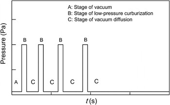
Figure 1 shows that the carburizing process carried out in a self-regulation mode is comprised of three stages. In stage (A), the furnace was evacuated and heated up to prepare for the following carburizing treatment. In stage (B), the carbon content on the surface reached saturation within a short time due to the high carbon potential of the injected gas medium. In stage (C), the carbon enriched on the external surface began to diffuse into the interior of the specimen after the furnace was re-evacuated. The furnace was/was not fed with the reducing gas mixtures in stage (B)/(C) in an alternate mode. Generally, the time period of stage (B) is set to be shorter than that of stage (C) to prevent deposited graphite from contaminating the furnace chamber.
Processing curve of VC.

After carburization, phase analysis, microstructure analysis, and microchemistry analysis were conducted for the metallographic specimens cut from the processed specimens. At first, the test specimens were mechanically grinded, polished, and etched with a solution of 40 mL HCl and 4 g H2C2O4. Then, the microstructures of the specimens were observed with a JSM-6510A SEM (Japan Electron Optics Laboratory Co. Ltd., Japan) equipped with a JED-2300 energy dispersive x-ray (EDX) microanalyzer (Japan Electron Optics Laboratory Co. Ltd., Japan) operated at 10 kV. Subsequently, microanalytical quantitative tests were carried out using a JXA-8230 electron probe microanalyzer (EPMA; Japan Optics Laboratory Co. Ltd., Japan) operated at 20 kV. X-ray diffraction (XRD) measurement was performed with a Rigaku D/MAX-RB diffractometer (Cu targets; Rigaku Corporation, Japan) operated at 40 kV. By the way, the kinetics of carburization was thermogravimetrically analyzed by calculating the mass gain per unit area of the carburized specimens.
III. RESULTS AND DISCUSSION
A. Microstructures on the cross-section of original alloys
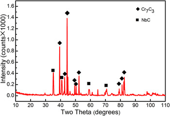
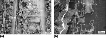
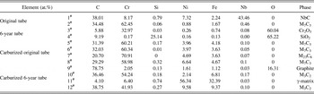
The x-ray diffraction pattern in Fig. 2 reveals that the main types of phases extracted from the original as-cast Cr35Ni45Nb alloy are chromium-riched M7C3 and niobium-riched MC. To reveal the microstructure features of the alloy, the cross-section of the metallographic specimen was electrolytically deep-etched to reveal backscattered 3D morphology of various carbides (Fig. 3). The chemical components at location 1# and 2# are listed in Table II, wherein the electron micro-probe analysis (EMPA) quantitative analysis of various chemical constituents is listed according to the corresponding figures. The conclusion drew was that the grain-boundary or interdendritic carbides mainly consist of two kinds of typical forms: lamellar white MC and long striped gray M7C3.
X-ray diffraction pattern recorded for the carbides extracted from the original Cr35Ni45Nb alloy.

The backscattered electron morphologies of the original Cr35Ni45Nb alloy by deep etching at (a) lower magnification and (b) higher magnification.


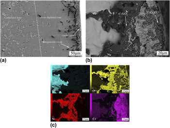
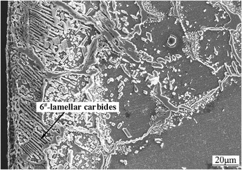
Figure 4(a) shows the microstructures of Cr35Ni45Nb alloy served for 6 years. The microstructure morphology on the cross-section of the tube is composed of three well-defined zones, namely, an outermost oxide scale, a subsurface carbide-depleted zone, and a deeper carburized zone. The external oxide scale (80 μm thick) has a two-layer structure consisting of an upper chromium oxide layer and a subjacent silicon oxide layer, both of which are identified by EDX elemental mapping [Fig. 4(b)] and EPMA analysis (see Table II). It is also found that the grain-boundary SiO2 branches propagated inwards along the intergranular sites in carbide-depleted zone for a depth of about 62 μm.
The inner wall features of the 6-year tube: (a) the morphology on the cross-section, (b) the composite oxide layers on the surface, and (c) their corresponding EDX elemental mapping (Ni, O, Si, and Cr).

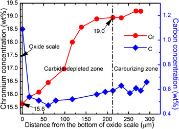
Additionally, a considerable amount of chromium in the subsurface is consumed due to the formation of Cr-riched oxide scale. The native carbides are dissolved gradually as the saturated carbon content increases due to depletion of Cr. As a result, the carbon released into the subsurface matrix diffuses into the interior of the specimen, contributing to the formation of carburizing zone. The chromium content ascends with the distance from the origin of carbide-depleted zone, as shown in Fig. 5. Evidently, the minimum content of Cr right beneath the oxide film is only 15.6 (wt%), while the critical Cr content is about 19.0 (wt%) at the border of the carbide-depleted zone and the carbide-riched zone. Thus, the conclusion drew was that the carbides will not decompose and dissociate until the Cr content in the carbide-depleted zone exceeds 19.0 (wt%). Furthermore, it should be noted that the above conclusion is only suitable for the condition with low carbon activity, similar to the practical operational conditions.
The content profiles of chromium and carbon in a carbide-depleted zone of the 6-year tube.

B. Carburizing features of original Cr35Ni45Nb alloy
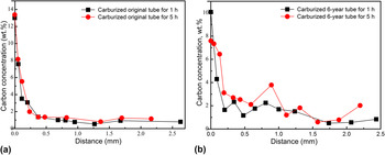
Figure 6 shows the carbon content profiles of various carburized tubes. The carbon content on the surface of the carburized original tube [Fig. 6(a)] reaches 13.4 (wt%) and then falls off sharply. The two curves have a similar trend, while the carbon content at 5 h is a little higher than that at 1 h.
Carbon content profiles of carburized specimens of the (a) as-cast original tube and (b) 6-year tube.

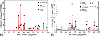
Figure 7(a) shows the phase transformations beneath the surface of the carburized original tube. The primary phases comprise austenite, M7C3, and MC. It should be noted that the effective region of XRD, which is less than 50 μm in depth generally, can only cover the phase information in the strongly carburized zone. The microscopic morphology varies a lot with increasing depth (Fig. 8). A continuous carbide scale, which is identified as M7C3 (Table II), formed on the outermost surface in interaction with the gas medium. However, sufficient subsurface chromium is required for the formation of carbide scale to sustain its continuity. The critical carbon content of M7C3 is given by Eq. (1) (Ref. Reference Farkas and Ohla22) as followed,
 $${C_{\max }} = \exp {\left( { - {{\Delta {G_0}} \over {RT}}} \right)^{ - {1 \over 3}}}{\left( {{\gamma _C}} \right)^{ - 1}}{\left( {{\gamma _M}} \right)^{ - {7 \over 3}}}{\left( {{C_M}} \right)^{ - {7 \over 3}}}\quad {\rm{,}}$$
in which, ∆G 0 is the Gibbs free energy change of M7C3, γ C , and γ M are activity coefficients of carbon and alloy elements (mainly Cr, Fe), respectively. As the carburizing time going on, significant segregation of Cr onto the surface directly caused depletion of Cr and increase of critical carbon content in the subsurface. As a result, a carbide-depleted zone just beneath the surface scale, where the contents of Cr and Ni are about 17.7 and 62.5 (wt%), respectively, is observed due to depletion of Cr.
X-ray patterns taken from the carburized layer of (a) the original tube and (b) the 6-year tube without oxide scale, both of which were carburized for 5 h.

The microstructure morphology of the carburized region in the original tube carburized for 1 h.

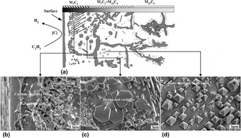
Additionally, with increasing depth, the intragranular precipitates present various geometrical shapes, such as parallel lamella, hexagon, quasi-octahedron, etc. The parallel lamellar carbides, which nucleated at the end of carbide-depleted zone, grew along a certain preferred orientation parallelly. The XRD and EMPA results (Table II) illustrate that the carbides are M7C3 as well. The region containing regular geometric carbide usually starts from the end of the carbide-depleted zone or lamellar carbide zone. These intragranular hexagonal and quasi-octahedral carbides substantially distribute dispersedly and mixedly, as shown in Figs. 9(b) and 9(c). The hexagonal carbides are identified as M23C6 and the quasi-octahedral ones are M7C3 (Table II). Statistics were carried out on the diameters of these geometric carbides after different processing times. The results reveal that the diameter of the hexagons changes from 6.5–8 μm (1 h) to 7–9.5 μm (5 h), implying that the growth rate increased in the first hour and slowed down within 1–5 h. However, the diameter of the quasi-octahedron increased from 1.7–2.2 μm (1 h) to 3.5–4 μm (5 h), which meant that the volume of the quasi-octahedron after 5 h was 8 times larger than that after 1 h. Therefore, once the carbide nuclei formed, the carburizing temperature of 1080 °C can provide sufficient energy to overcome their energy barrier of growth, which is beneficial to Ostwald ripening. Furthermore, the secondary precipitates can grow up into perfect regular shapes under the conditions that adequate carbon atoms, energy and nucleation sites are supplied, and there are fewer dislocations in the interior of grains.
Different microstructure morphologies in the carburized region of the original tube after carburization: (a) schematic diagram of the carburized region; (b) carbide scale and carbide-depleted zone; (c) hexagonal carbides; and (d) quasi-octahedral carbides.

The lamellar morphology, which indicates that there is a specific orientation relationship between the carbides and austenite matrix, was mainly induced by high Ni/Cr contents of Cr35Ni45Nb. Alloys with higher contents of both Cr and Ni simultaneously are rarely seen, usually presenting greater penetration resistance for carbon. In this less favorable kind of medium for carbon infiltration, the diffusion paths are not random, thereby resulting in nonrandom growth orientation of carbides finally. In fact, the actual orientations of most lamellar carbides have the smallest angle with respect to the diffusion direction, the lowest interfacial energy and strain energy of growth. Carbides tend to overcome relatively low activation energy to nucleate and grow two-dimensionally in the {111} lattice plane (the habit plane) of austenite matrix. The whole process is similar to the case of ingot solidification. The orientation of carbides is inclined to be parallel to the direction of the maximum carbon concentration gradient so as to achieve the highest growth rate, while the orientation of the columnar grains during solidification is parallel to the direction of the maximum heat or temperature gradient. The generated continual interfaces between carbides and matrix contribute to fast inward-penetration of carbon, and the incoming carbon also serves as a material supply for a rapid extension of the growth frontier. Nevertheless, the lamellar morphology also changes gradually over time. Specifically, the thickness of the lamellas decreased, whereas the intervals increased from 1 to 5 h, which implies that the lamellar carbides did not always stably exist, but as an intermediate form in a carburizing process. The main function of such intermediate may be to coordinate the two contradictory factors including low permeability due to high Ni/Cr contents and high concentration gradient of carbon induced by rapid over-saturated carburization. The lamellar carbides would eventually coalesce or transform to other morphologies.
With respect to the above-mentioned strongly carburized regions, such as the lamellar carbide zone or the regular geometric carbide zone, both of which are referred to as “strong carburized regions”, the region below them is referred to as a “diffusion region”, where intragranular precipitations of carbides have a significant reduction. A few fine carbide particles and a handful of carbide needles are formed near the original primary carbides due to the residual carbon flux penetrated just along the grain boundaries or interdendritic sites. The area below the diffusion region, which is referred to as an “aging area”, is scarcely affected by carburization. However, those fine secondary carbides are also dispersed around the primary carbides due to high-temperature aging.
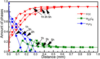
The simulated profiles of the amount of phases formed during carburization at 1080 °C with DICTRA software are shown in Fig. 10. The blocking effect of dispersed carbide particles is taken into account by bringing in a labyrinth factor, which is set to be the square of volume fraction of precipitates to multiply the diffusivities. Reference Borgenstam, Höglund, Ågren and Engström23 It is clearly shown that the amount of M7C3 is approximately 1.0 at x = 0, implying that the surface is almost occupied by M7C3 carbides corresponding to the carbide scale in Fig. 9(a). The amount of M7C3 has a sharp drop near the starting point and then turns gentle with increasing distance from the surface. In the last stage of the curve of M7C3, the amount of M7C3 decreases to zero, while the curve of M23C6 begins to ascend. This range is consistent with the mixed regions including M7C3 and M23C6 carbides shown in Fig. 9. The curve of M23C6 peaks exactly on the location where M7C3 disappears and descends slowly to a constant value subsequently. Apparently, with the increasing carburizing time, the endpoint of the curve of M7C3 and the starting point of the curve of M23C6 shift to the right at the same time.
The simulated content distributions of various phases in the carburized original tube with DICTRA software.

C. Carburization features of 6-year Cr35Ni45Nb tube
The carbon content curves of the carburized 6-year tubes are shown in Fig. 6(b). As can be seen from the figure, carbon beneath the surface still segregated after 1 h, and the surface carbon content is 10.07 (wt%). With the carburizing time going on, the absolute value of the curve gradient gradually decreased, implying the occurrence of considerably massive internal carburization. The content of the accumulated carbon on the surface was reduced to only 7.59 (wt%) after 5 h, implying that the capability of the alloy substrate to resist the carbon attack deteriorated significantly. Similarly, the curves behave more relaxedly compared with that in Fig. 6(a). The differences derived from the original service conditions may be explained by significant precipitations of graphite (explained below) across a wide area beneath the surface.
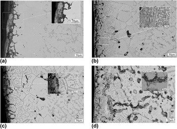
Figure 11 shows microstructure morphologies on the cross-section of the carburized 6-year Cr35Ni45Nb specimens under different processing conditions. As can be seen, significant microstructure changes occurred after massive carbon swarmed in. As the surface oxide scale was not removed before carburization, Cr2O3 would be gradually carbonized after 1 h due to high carbon activity on the surface [Fig. 11(a)]. XRD and EPMA results (Table II) reveal that the in situ carbonized product is M3C2. However, the adjacent SiO2 still kept the same even after 5 h, displaying more excellent stability with respect to Cr2O3 in a strongly reducing environment at 1080 °C. Owing to continuous and thick Cr2O3 scale as well as dense and stable SiO2 with a few pores and microchannels, the composited oxide layers show excellent anticarburizing capability. Apparently, carburization has hardly occurred below the oxide film after 1 h, resulting in no precipitations of carbides. Only a few thin carbide sheets precipitate at the grain boundary just beneath some localized surfaces.
The microstructures on the cross-sections of the 6-year Cr35Ni45Nb tube under different VC conditions: (a) specimen with oxide scale, VC 1 h; (b) specimen with oxide scale removed, VC 1 h; (c) specimen with oxide scale, VC 5 h; and (d) specimen with oxide scale removed, VC 5 h.

Figure 11(b) shows the microstructures of the specimen with oxide scale removal, which is carburized for 1 h. Since the effective protective barrier against carbon attack has been greatly reduced, huge amounts of carbon flow penetrate inwards for about 220 μm deep along intergranular and intragranular paths simultaneously. In the intergranular sites, typical characteristics of carbide morphologies are transgranular carbide sheets like twin and in-between dispersed carbide particles. The twins-like carbides may be formed at stacking faults or annealing twins on account of nucleation or formation sites. Since there is a relatively large carbon flux of bulk diffusion, the intragranular precipitate particles are tiny and homogeneous compared to that in Fig. 11(c).
Figure 11(c) shows the microstructures of the specimens with surface oxide carburized for 5 h. Obviously, Cr2O3 has already been in situ carbonized completely. However, volume expansion due to carbonization and reduced adhesion capacity lead to drastic spallation of the oxide film (Fig. 11). Due to the lack of first line of defense, carbon can quickly penetrate into the interior of the specimen through the SiO2 pores and generate a few carbide sheets along the boundary of the original carbide-depleted zone. As less carbon flow through bulk diffusion, the intragranular precipitates are formed as parallel lamellar twins across whole grains and carbide needles with certain orientations. The EPMA analysis (Table II) shows that the carbides are M7C3. Meanwhile, the amount of internal patches also increases slowly as a result of graphite precipitation.
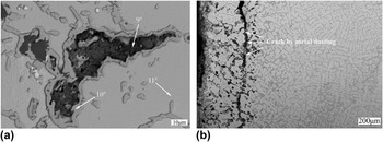
Figure 11(d) shows the microstructures of the specimens with oxide removal, which are carburized for 5 h. Due to excessive carburizing time and the lack of oxide scale, significant carbon attack occurred in the interior of the specimen, and graphite precipitated widely in depth in the range of about 510 μm. The graphite area [Fig. 12(a)] was microchemically analyzed by EMPA at different locations, as shown in Table II. The results show that location 6# corresponding to the black areas is mainly graphite, 7# is M3C2, 8# is Cr2O3, and 9# is γ matrix. Table II reveals that the weight percent of Cr in position 9# is 6.392, and the saturated carbon content of the matrix calculated using Thermo-Calc software is 0.95. Actually, the measured carbon content is 0.947 (wt%), which is the saturated carbon content. The original M23C6 carbides in the region below the graphite area gradually transform into M7C3. In the bulk of M7C3, vermiculate precipitates are formed, as shown in Fig. 13. However, secondary carbides do not exist in the wide γ matrix of this region any more. EMPA analysis was performed on location 10#, and the result shows that the Cr content is 13.58 (wt%), which is lower than the critical content of carbide decomposition, namely, 19.0 (wt%). Thus, the secondary carbides cannot be stable all the time.
The graphitization area (a) and cracks caused by metal dusting (b) of the carburized 6-year tube with surface oxide scale removed.

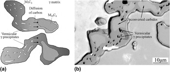
Schematic diagram (a) and morphology (b) of the transformation from interdendritic M23C6 to M7C3 at high carbon activity.

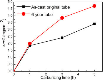
The anticarburizing capability of the 6-year tube with surface oxide removal is considerably weakened (Fig. 14). The weight gain of the tube is 4.714 mg/cm2 after 5 h, which is 37.5% more than that of the original tube. Before the carburization of the primary carbides of the 6-year tube, the width of which is 4–9 μm, implying that the primary carbides have already coalesced and coarsened greatly compared to that of the original tube. After the carburization, the widths of primary carbides are increased to 20–40 μm averagely, even up to 80 μm in some local areas. Due to a rapid extension of the carbides, Cr in the matrix surrounding them diffuses quickly toward the boundary sites inevitably, thereby leading to a sharp decline in content. In the carburized region with no graphite formed, the transition can be represented by the following equation:
 $${{\rm{M}}_{23}}{{\rm{C}}_6} + [{\rm{C}}] \to {{\rm{M}}_7}{{\rm{C}}_3} + \gamma \quad {\rm{.}}$$
Carburizing kinetic curve of Cr35Ni45Nb alloys under different service conditions at 1080 °C.

The interdendritic carbides exist as M23C6 stably when the a c is still lower before carburization. However, M23C6 is transformed into M7C3 gradually by in situ transition due to the increased a c in a carburized region after carburization (Fig. 14). The products obtained by transition are similar to divorced eutectics in view of morphological characters. However, in consideration of the nature of solid–solid transformation, the products have a divorced eutectoid structure. This phase change results in that parts of original elements in M23C6 are dissolved into the surrounding γ solution. Nevertheless, since some elements could not reach the carbide-γ boundaries due to the dynamic factors, they were stuck inside the bulk carbide to form vermiculate precipitates. Kaya et al. Reference Kaya6,Reference Kaya, Krauklis and Young24 have conducted a study in alloy HK40 (Cr25Ni20) by TEM, revealing that the vermiculate precipitates are γ (austenite) phases. These vermiculate precipitates also coalesce and coarsen with decreasing distance from the surface. This structure is conductive to crack propagation along the interdendritic network. Furthermore, continuous carbon flow penetrates along the carbide network and some severely supersaturated C deposits at the vermiculate γ phases in the form of graphite. This phenomenon is called “metal dusting”, which is mainly induced by an environment of high carbon activity.
There are two speculations about the formation mechanisms of metal dusting in the 6-year tube with surface oxide removed after carburization. Firstly, the Cr content in the matrix around the primary carbides is decreased to about 6.4 (wt%) (Table II), which is not sufficient to continue with the formation of large amounts of chromium carbides. The excessive carbon has no medium to resolve in, thereby precipitating as graphite, or otherwise the acetylene spreading along the vermiculate γ and other defects is catalyzed by Fe or Ni to form graphite. Secondly, the carbon derived from catalytic decomposition of acetylene is absorbed immediately by the matrix to reach a saturated state, resulting in the formation of stable and unstable carbides. These unstable carbides break down under certain conditions to form graphite.
Since there is a large difference in densities and coefficients of thermal expansion between the graphite and the alloy matrix, large amounts of precipitations of graphite can result in the formation and propagation of macroscopic cracks. Of course, the prerequisite of metal dusting of the 6-year tube is a considerable consumption of Cr caused by intergranular oxidation or internal carburization near the inner wall of the tube during service. Fortunately, the surface composite oxide layers have a good effect on retarding or inhibiting the occurrence of metal dusting. If the oxides are not removed before carburization, the process of metal dusting also includes a gestation period for the carbonization of oxide scale, the spallation of carbide scale, and internal carburization.
Since there is hardly no measurable solubility of carbon in Cr2O3, carbon cannot travel through this kind of perfect film. Reference Grabke and Wolf3 However, the actual oxide film under operational conditions cannot always remain continuous and dense. There are several formation mechanisms of the pores and microchannels in oxides Reference Wolf, Grabke and Schmidt14 : (i) decomposition of the oxide layer, particularly at the grain boundary; (ii) rupture of scale due to growth stress in the process of thickening, especially when the oxide scale is thick enough; and (iii) imperfect joining of growing grains. In addition, various defects in the oxide film can be caused by tension in the scale induced by a high-temperature creep process, thermal shock in the process of decoking, thermal stress in operation, etc. The traverse defects can provide diffusion paths for the carbon containing molecules, so that carbon may penetrate into the interior of the specimen through the oxide layer. However, in the present study, the mechanisms of defect formation are not limited to those described above. In a reducing environment of high temperature, Cr2O3 itself cannot be stable all the time. The oxide in an environment of high carbon activity was carbonized, causing a gradual degradation of its anticarburizing capability.
In the carburized region, only M3C2 and M7C3 type chromium carbides are found, as shown in Fig. 7(b) and Table II. In the environment of high carbon potential, M3C2 is more stable near the surface than the carbides M7C3 and M23C6, thereby becoming the first reaction product. The carbonization process of Cr2O3 can be indicated by Eq. (3) below.
 $${\rm{C}}{{\rm{r}}_2}{{\rm{O}}_3} + {{13} \over 9}{{\rm{C}}_2}{{\rm{H}}_2} = {2 \over 3}{\rm{C}}{{\rm{r}}_3}{{\rm{C}}_2} + {{13} \over 9}{{\rm{H}}_2}{\rm{O}} + {{14} \over 9}{\rm{CO}}\quad {\rm{.}}$$
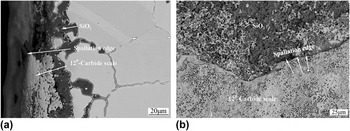
In fact, the mechanisms of “diffusion by forming defects” and “carbonization of oxide” are also promoted mutually. A large number of pores and microchannels provide paths and sites for carbon-containing atmosphere to travel into the interior of the oxide, to decompose, and then to react with the oxide particles, thereby accelerating the carbonization of the scale. And carbide particles generated in the oxide scale also induce more internal defects in return. When most oxides were reduced after adequate time, the adhesion of the carbide scale to the subsurface changed significantly compared to that in the original state. Furthermore, the carbide layer could not bear the original tensile stress due to its low coefficient of thermal expansion, resulting in significant spallation of the carbide layer [Fig. 15]. It is noted that the carbon potential in the actual service process is much lower than that in the present study, leading to a significant decrease in carbonation kinetics.
Characteristics of carburizing resistance of the composite oxide scales of the carburized 6-year tube: (a) the lateral morphology and (b) the superficial morphology.

Compared with the outermost Cr2O3, the subsurface SiO2 shows better stability. The reason why SiO2 is not reduced is that the thermodynamic stability of SiC is far less than that of Cr3C2 and Cr7C3 in the highly reducing atmosphere. And the low solubility to carbon makes it possess excellent resistance to carburization. However, the SiO2 grains cannot laterally grow to connect with each other, since the Si content, which is lower than the critical content, can not ensure the continuity of the film. It is because of this discontinuity that the anticarburizing capability is deteriorated significantly because carbon can penetrate through the gaps in the oxides into the interior of the specimen.
In conclusion, the Cr2O3 and SiO2 layers cooperate to prevent carbon from infiltration. The anticarburizing capability of the specimen is ascribed to three important factors, namely, continuity, compactness, and high-temperature stability of the oxide layers, and none of which is dispensable. The enlightenments from the above experiment are that: (i) Si, Al, or other microalloying elements should be reasonably added and regulated to achieve perfect anticorrosive performance without deteriorating mechanical properties; (ii) the periodic decoking process accompanied by spallation and regeneration of the composite oxides should ensure that the surface film is completely restored to a continuous and dense status before pumping pyrolysis gases again.
IV. CONCLUSIONS
-
(1) High carburizing rate, efficiency, and carbon activity are important features of VC process, by which good carburization effects are achieved in the present study. In general, regardless of the service state of the tubes, the diffusion of carbon is always accompanied by heterogeneous or multiphase reactions.
-
(2) As for the as-cast original tube, several distinct microstructure transitions occurred after carburization. Several new zones were formed, including bulk carbide scale on the outmost surface, a subsurface depleted zone, a lamellar carbide zone, a regular geometric carbide zone, a diffusion region, and a weakly affected region. All of these regions constitute a layered structure comprising a M7C3 zone, a M7C3–M23C6 mixed zone, and a M23C6 zone in sequence in view of phases.
-
(3) As for the 6-year tube, the chromium oxide scale became the first line of defense against carbon attack. However, the chromium oxide scale was incapable of continuing to be a protective film due to its severe carbonization in a strongly reducing environment. Meanwhile, the adjacent SiO2 layer showed high chemical stability, but unfortunately, low content of Si was unable to maintain the continuity of SiO2 layer, that is, there were too many pores in the layer which were unable to block the carbon flow entirely. The continuity, density, and high-temperature stability of oxide scale were critical for achieving excellent anticorrosion capability. As the oxide layers were removed or carbonized adequately, inconceivable internal carburization occurred in the 6-year tube. Graphite widely precipitated in the center of the primary carbides in depth of about 510 μm, and the primary carbides within the deeper carburized region transformed from M23C6 to M7C3, which were accompanied by precipitation of vermicular γ-phase in the primary carbides and decomposition of intragranular secondary carbides. Consequently, significant degradation of microstructures and formation of macrocracks resulted in severe coalescence and coarsening of carbides as well as precipitation of graphite.
ACKNOWLEDGMENTS
The authors are grateful for the financial support and facilities provided by China Special Equipment Inspection and Research Institute and Beijing Institute of Aeronautical Materials, respectively.