I. INTRODUCTION
Carbon nanotubes are considered as versatile materials that can find applications in various devices, including plasma display, synthetic motor and single molecule light emitting diode.Reference Chen, Perebeinos, Freitag, Tsang, Fu, Liu and Avouris1–Reference Ren, Huang, Xu, Wang, Bush, Siegal and Provencio4 Different types of nanotube (i.e., n-type, p-type or metallic-type) exhibit different electronic behaviors for particular utilization.Reference Behabtu, Young, Tsentalovich, Kleinerman, Wang, Ma, Bengio, ter Waarbeek, de Jong, Hoogerwerf, Fairchild, Ferguson, Maruyama, Kono, Talmon, Cohen, Otto and Pasquali5–Reference Saha, Jiang and Martí7 However, methods to render these properties usable, such as self-assembly or micro-fabrication, are costly and time consuming, preventing themselves for scale up applications. An effective approach to circumvent the problem is through solution process, providing solubility in a certain solvent that can be fabricated on larger area or large array devices. Therefore, tremendous efforts have been made to uniformly disperse carbon nanotube in solutions.Reference O'Connell, Boul, Ericson, Huffman, Wang, Haroz, Kuper, Tour, Ausman and Smalley8–Reference Richard, Balavoine, Schultz, Ebbesen and Mioskowski10 Surfactants, and especially polymer wrapping agents, are considered as a well established method to aid nanotube suspension. The structure of the polymers is specifically designed for desired functionality that can correlate the surface of carbon nanotube. Typically 0.1–0.01% (by weight) carbon nanotube can be stabilized and well dispersed in the presence of surfactant.
As one of the most promising candidates serving for this purpose, conductive polymers have attracted increasing interests in the past decades.Reference Tang and VanSlyke11,Reference Burroughes, Bradley, Brown, Marks, Mackay, Friend, Burns and Holmes12 In particular, soluble conductive polymers are highly desired for large scale manufacture of low cost electronic devices.Reference Braun and Heeger13 In recent years, screen and inkjet printing have been successfully applied to this area, significantly lowering the cost for production.Reference Hebner, Wu, Marcy, Lu and Sturm14,Reference Pardo, Jabbour and Peyghambarian15 Polymer composites, formed by coupling semiconducting polymers with carbon nanotubes, can exhibit tunable electronic properties through altering their surface correlations that can be achieved by innovating polymer structure.
Single-walled carbon nanotube (SWNT) has been demonstrated to be viable as charge injection material for application in OLEDs.Reference Fournet, O'Brien, Coleman, Horhold and Blau16–Reference Dalton, Blau, Chambers, Coleman, Henderson, Lefrant, McCarthy, Stephan and Byrne18 However, the applications are limited by the available materials to render the SWNT soluble as well as its compatibility to the light emitting materials. Poly(m-phenylene-vinylene-co-2,5-dioctyloxy-p-phenylene-vinylene) (PmPV) is one of the conducting polymers which has been found to be able to wrap around the SWNT to stabilize the tubes in solution phase,Reference Mc Carthy, Coleman, Czerw, Dalton, Carroll and Blau19,Reference Fournet, Coleman, Lahr, Drury, Blau, O'Brien and Horhold20 yet limited solubility of SWNT in other conductive polymer systems is one major obstacle for wide range applications.
In this report, we designed and synthesized a new conductive polymer poly(2,7-9,9-(di(oxy-2,5,8-trioxadecane))fluorene) (PFO) (Scheme 1) with polar ethylene oxide (EO) side chains. EO is a versatile building block wildly incorporated into functional polymer backbone due to its high polarity and enhanced chemical stability.Reference Jia, Yuan, Zhao, Hu and Baker21–Reference Hu, Yuan, Jia and Baker24 The morphology, surfactant property, and electronic property of this novel conductive polymer were studied, along with its nonpolar analogue poly(2,7-9,9 didecly fluorene) (PF). Both are polyfluorene-type structure that attracts great attention in OLED applications.Reference Deng, Yuan, Jia and Liu25 Our results suggest that this surfactant conductive polymer with EO polar side chain is able to stabilize the SWNT dispersions in organic solutions at 1% (by weight) concentration level. Since there is no permanent bond formation between PFO and SWNT, the stabilization effect is found reversible. The polymer can be washed off from carbon nanotube surface with solvent.
Chemical structure of PF (left) and PFO (right) conducting polymers as stabilization agents studied in this work.

II. EXPERIMENTAL
A. Materials
Triethylene glycol monomethyl ether (95%), p-toluenesulfonyl chloride (99%), 2,7-dibromofluorene (97%), triphenylphosphine (99%), 2,2-dipyridyl (≥98%), zinc powder (100 mesh, 99.998%), nickel (II) chloride (98%), magnesium sulfate (anhydrous, 99.5%), potassium hydroxide (≥85%, pellets), sodium bicarbonate (≥99.7%), and sodium hydride (95%) were obtained from Aldrich and used as received. The as-prepared (AP) grade SWNT tube was purchased from CarboLex® (diameter 1.2–1.5 nm, length 2–5 μm) and used without further purification. The poly(3,4-ethylenedioxythiophene)/polystyrene sulfonate (PEDOT/PSS) aqueous solution was purchased from Aldrich and filtered through a 0.45 μm syringe filter. Indium tin oxide (ITO) coated glass slide was purchased from Aldrich with surface resistance at 13 Ω/sq. All chemicals and solvents were American Chemical Society (ACS) reagent grade and used as received without further purification unless otherwise specified.
B. Instruments
1H-NMR (proton nuclear magnetic resonance) spectra were recorded on a Bruker Avance500 II (Bruker Corporation, Billerica, Massachusetts), using the deuterated solvent as lock and the residual solvent as internal standard. Scanning electron microscope (SEM) images were collected with a JEOL JSM-7500F field emission scanning electron microscopy with an accelerating voltage of 15 kV using the high vacuum mode at room temperature. Transmission electron microscopy (TEM) was conducted at the National Center for Electron Microscopy, Lawrence Berkeley National Laboratory using a JEOL 200CX microscope (JEOL Ltd., Pleasanton, California) operating at 200 kV. A RMC Boeckeler PR XL Ultramicrotome (Boeckeler, Tucson, Arizona) was used to prepare thin sections (approximately 50 nm) for TEM. Samples were embedded in low viscosity Spurr's epoxy for added stability when sectioning. Films were cryomicrotomed at −100 °C using a cryogenic attachment and a glass knife. The electronic properties were studied with a Solartron™ 1286 electrochemical interface instrument (Solartron, Sussex, United Kingdom). Transmittance spectra between 300 and 800 nm of composite films on glass or ITO on glass were recorded using a PerkinElmer Lambda 19 UV/Vis/IR spectrophotometer (Perkin Elmer, Waltham, Massachusetts).
C. Synthesis of PFO conducting polymer
1. 10-Tosyloxy-2,5,8-trioxadecane
Synthesis followed a literature procedure.Reference Jullien, Canceill, Lacombe and Lehn26 Triethlyene glycol monomethylether (10 g, 61 mmol) was dissolved in tetrahydrofuran (THF, 50 mL) and cooled to 0 °C in an ice bath. A solution of KOH (5.6 g, 100 mmol) in 10 mL water was slowly added to the mixture, followed by TsCl solution (9.5 g, 50 mmol in 20 mL THF) added drop-wise over 20 min with vigorous stirring. After stirring overnight in an ice bath, the mixture was poured into distilled water (200 mL) and extracted with CH2Cl2 (2 × 100 mL). The combined organic solutions were washed with saturated NaHCO3 solution (2 × 100 mL), distilled water (2 × 100 mL), dried over MgSO4, and concentrated under reduced pressure to give 15.7 g as a clear colorless oil in 99% yield. 1H-NMR (300 MHz, CDCl3) δ 2.3 (s, 3H), 3.22 (s, 3H), 3.28–3.70 (m, 10H), 4.04 (t, 2H), 7.24 (d, 2H), 7.68 (d, 2H).
2. 2,7-Dibromo-9,9 (di(oxy-2,5,8-trioxadecane))fluorene
2,7-Dibromofluorene (5.0 g, 15.4 mmol) was dissolved in dried THF solution (30 mL). NaH (1.0 g, 40 mmol) was added to the THF at room temperature and refluxed for 5 h. 10-Tosyloxy-2,5,8-trioxadecane (11.8 g, 37 mmol) in 20 mL of dry THF was added dropwise to the refluxed solution. The mixture was allowed to reflux over night, then cooled down, poured into distill water and extracted with chloroform (CF) (2 × 100 mL). The combined organic solutions were washed with saturated NaCl solution (2 × 100 mL), distilled water (2 × 100 mL), dried over MgSO4, and concentrated under reduced pressure. Crude oil was further purified by column chromatography using hexane/ethyl acetate (50/50) as eluant solvent (R f = 0.12). After removal of solvent, a colorless liquid was obtained as final product (5.7 g, 60% yield). 1H-NMR (300 MHz, CDCl3) δ 2.34 (t, 4H), 2.77 (t, 4H), 3.10–3.60 (m, 22H), 7.40–7.60 (m, 6H).
3. Poly(2,7-9,9 (di(oxy-2,5,8-trioxadecane))fluorene)
Polymerization followed a literature procedure.Reference Pei, Qibing, Yang and Yang27 2,7-Dibromo-9,9 (di(oxy-2,5,8-trioxadecane))fluorene (4.0 g, 6.3 mmol), triphenylphosphine (164 mg, 0.63 mmol), zinc powder-100 mesh, 99.998% (1.3 g, 19 mmol), 2,2-dipyridyl (49 mg, 0.31 mmol) and nickel chloride (16 mg, 0.13 mmol) were charged in a 20 mL flask. Dry DMAc 3 mL was added via syringe and the mixture was stirred at 80 °C for 3 days in He glove box. After cooling down to room temperature (r.t.), the polymer was poured in a 200 mL methanol/concentrated HCl (50/50) mixture. The mixture was precipitated in 500 mL of water, filtered, dried, and redissolved in 100 mL of CF solution, washed with deionized (DI) water (2 × 200 mL) and concentrated into 10 mL CF solution and precipitated in hexane (2 × 200 mL) to give 2.7 g final product in 68% yield. Mn 9400; polydispersity index (PDI) 1.6 (gel permeation chromatography [GPC] using polystyrene standard). 1H-NMR (300 MHz, CDCl3) δ 2.59 (b, 4H), 2.91 (b, 4H), 3.20–3.60 (m, 22H), and 7.50–8.00 (m, 6H). Elemental analysis calc. for C, 0.7101; H, 0.0795; found C, 0.7084; H 0.0800. PF was synthesized according to the existing literature.Reference Stephan and Vial28
D. Solution dispersion process of SWNT with polymers
The AP grade SWNT contains 60% of pure carbon nanotube and 40% of amorphous carbon and catalysts. The dispersion of SWNT is achieved by sonication of the mixture of SWNT, polymer and solution using a Branson 1210 sonicator (Branson, Danbury, Connecticut). The solutions were then left without vibration for a week up to 4 mo to sediment. The top part of the solutions was studied and used to cast films.
E. Composite film formation and physical property testing
The electronic properties were studied with a Solartron™ 1286 electrochemical interface instrument. The resistance of the ITO glass is 13 Ω/sq. The ITO coated glass was successively cleaned in saturated KOH/isopropanol solution, followed by 20 min sonication three times, then cleaned in acetone, isopropanol and methanol. The cleaned ITO glass was finally put under oxygen plasma treatment to complete purification process. The conductive polymers were spin coated on the class in clean room.
The PEDOT/PSS aqueous solution was purchased from Aldrich and filtered through a 0.45 μm syringe filter. The PEDOT/PSS layer was spin coated at 1500 rpm, resulting in a 120 nm film. The conductive polymer solutions were filtered with 0.45 μm syringe filter. The example of a composition to formulate SWNT/conductive polymer composite is 3.3 g AP grade SWNT/100 g conductive polymer/10 L solvent. (3.3 g of AP grade SWNT contains 2 g of pure SWNT). The PFO (or SWNT composite) layer was spin coated at 1000 rpm, resulting in a 40 nm film. Transmittance spectra between 300 and 800 nm of composite films on glass or ITO on glass were recorded using a PerkinElmer Lambda 19 UV/Vis/IR spectrophotometer. 50 nm of metal electrode cathode was thermally evaporated onto the PFO (or SWNT composite) film surface at a base pressure of 10−6 Torr. A shadow mask of 0.3 cm2 area was used to define the cathode.
III. RESULTS AND DISCUSSION
A. Synthesis of PFO conducing polymer
Scheme 2 shows the 2-step synthetic route of PFO conducting polymer. EO side chain was grafted onto 2,7-dibromofluorene through SN2 reaction. Monomers were later polymerized into surfactant PFO through a literature procedure.Reference Pei, Qibing, Yang and Yang271H-NMR and GPC were used to characterize polymers. GPC shows molecular weight at around 9.4 K and a PDI at 1.6.
Synthesis of poly(2,7–9,9-(di(oxy-2,5,8-trioxadecane))fluorene) (PFO) conducting polymer.
B. Solvent effects on the solubility of SWNT
Figure 1 shows the resulting dispersions of SWNT with PF as surfactant in respectively chlorobenzene (CB) and CF solutions [Figs. 1(a) and 1(b)], along with the results of using PFO as surfactant in CB and CF solutions [Figs. 1(c) and 1(d)]. The mixtures were obtained by sonically agitated for 1 h at r.t. and left without disturbance for a week before pictures were taken. The SWNT evidently precipitated out from both solutions when PF was used as stabilization agent. With nonpolar alkyl side chain and rigid polyfluorene backbone, PF conducting polymer was unable to present any significant molecular interactions toward SWNT structure, and, therefore, cannot hold homogeneous suspension in the solution phase. SWNTs were initially dispersed during sonic agitation, but aggregated and precipitated out after long standing. SEM also confirms the absence of the SWNT in the solvent cast polymer films using upper level clear solutions presented from Figs. 1(a) and 1(b). However, PFO polymer possesses strong surfactant properties due to its polar EO side chains in combine with the nonpolar backbone structure. PFO/CB solution is able to suspend and stabilize 0.02% (by weight) SWNT in the solution phase [Fig. 1(c)], which correlates to 2% of SWNT to PFO polymer in weight ratio. PFO/CF solution is also able to suspend and stabilize SWNT, but in a far less extent as presented in Fig. 1(d). No aggregate was observed under 400× optical microscopy in both cases with PFO as surfactant.
Photos of SWNT dispersion in polymer solutions. (a) SWNT/PF/CB solution; (b) SWNT/PF/CF solution; (c) SWNT/PFO/CB solution; (d) SWNT/PFO/CF solution.
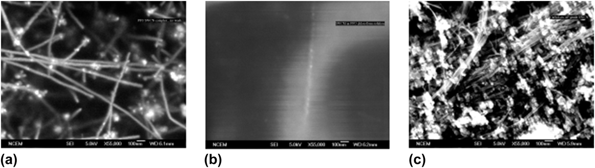
The SEM studies (Fig. 2) show consistency with optical microscopy results. Figure 2(a) was acquired from the SWNT/PFO film cast using the upper layer solution of SWNT/PFO/CB [Fig. 1(c)], while Fig. 2(b) was obtained from the SWNT/PFO film cast using the upper layer solution of SWNT/PFO/CF [Fig. 1(d)]. As Fig. 2(a) shows, the SWNTs are abundant in the upper layer CB solutions and they are well suspended. However, in SWNT/PFO/CF casted film [Fig. 2(b)], one single tube rope was detected. This sporadic distribution of SWNT is typical in all the areas studied. In both cases, SWNTs are not distributed as individual tubes. They aggregate into ropes instead. We found the aggregate size is very uniform compared to the AP grade SWNT [Fig. 2(c)], and less amount impurities were carried over to the composite films after weeks of sediment.
The interaction between PFO and SWNTs affects the suspension of the SWNTs in the solution phase. The polymer wrapping structure can be derived from different solubility behavior of SWNT in CB or CF solutions. The polar side chains and nonpolar backbone of PFO will preferably aggregate in different solvents. Since CF and CB are two distinctive types of solvent systems, they have resulted in two completely different aggregation patterns as shown in Figs. 3(a) and 3(b). CF is a highly polar solvent, which selectively solvates side chains and forces the backbone to aggregate [Fig. 3(a)]. In contrast, CB is a weak polar aromatic solvent, which prefers to interact with the conjugated polyfluorene backbone through π–π stacking interaction [Fig. 3(b)].Reference Nguyen, Doan and Schwartz29 The polar polymer wrapping of SWNT using polyethylene oxide (PEO) or polypropylene oxide (PPO) has been rationalized in the literature as the polarization effect of the polar polymer on the SWNT π electrons.Reference O'Connell, Boul, Ericson, Huffman, Wang, Haroz, Kuper, Tour, Ausman and Smalley8–Reference Richard, Balavoine, Schultz, Ebbesen and Mioskowski10 PFO forms aggregates in CF as shown in Fig. 3(a). The arrangement with the polar side chain on the outside may limit the extent of the interaction between the polymer and SWNTs, and result in dispersion of less SWNTs as is observed. The EO side chains are clustered inside the aggregate while polyfluorene backbones form the outer envelope in the CB solution as shown in Fig. 3(b). The SWNT may reside in the center of the cluster. The nonpolar backbones provide a template while flexible oligoethyleneoxide side chains wrap around the SWNT as shown in Fig. 3(c). Therefore CB/PFO solution with the polar groups on the inside of the aggregate yields the best ability to stabilize SWNT in the disperse phase as shown in Fig. 3(d).
Selective aggregations of PFO in (a) CF, (b) CB, (c) PFO preferred wrapping of SWNT, (d) a hypothetical SWNT polymer micelle. (In the drawings, the blue lines represent rigid PFO backbones; the flexible red branches represent methyltriethyleneoxide side chains; and the tubes represent SWNTs).
C. Solid-state morphology of composite films
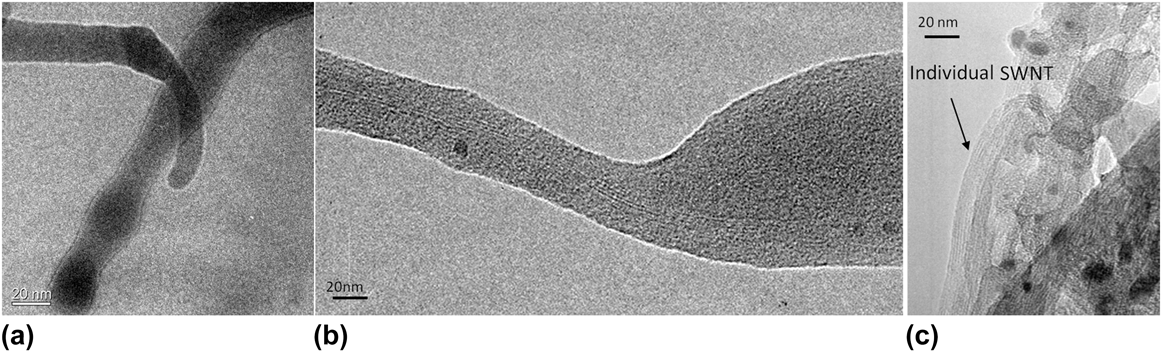
PFO can stabilize SWNTs at higher concentration in CB solution than PF. After 1-wk sediment, more “tubes” were observed in the solution casted composite films where PFO was used as surfactant. This phenomenon is originated from the strong affiliation of PFO with SWNT in solution phase. The solid-state morphologies of SWNTs instant dispersion in PFO/CB and PF/CB are also different. The SWNTs and CB solutions were ultrasonically treated for 1 h either with PFO or PF, and copper grids were instantly dipped into the solutions followed by air dried. TEM was used to examine the different morphologies of the two samples at the thin edge. PFO surfactant yields smooth coating on the SWNTs [Fig. 4(a)], whereas PF shows clear edges resulted from polymer aggregation [Fig. 4(b)], indicating stronger interactions between PFO polymer structure and SWNTs which facilitate the dispersion and suspension of the SWNTs. Figure 4(c) shows a PFO/SWNT composite film. This sample was treated with toluene to leach out the polymers, revealing tubes that might have otherwise been visually obscured within the polymer matrix. Individual tube can be clearly observed with space in between the tubes where polymer resided. The PFO polymers were gradually moved from SWNTs. Separated tubes were observed after ultrasonication.
TEM images of (a) PFO associated SWNT show smooth coating on surface of SWNTs. (The scale bar is 20 nm.) (b) PF associated SWNTs show aggregation of polymer. (c) Individual tubes can be seen after the PFO leached out.
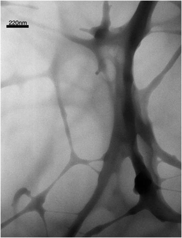
The bulk morphology of the composite SWNT with PFO was studied by first microtome the sample, followed by the TEM analysis. In composite preparation process, the ultrasound dispersed CB/PFO/SWNT solution was allowed to sediment for 4 mo. The upper solution was then taken to cast film without disturbing the precipitate at the bottom. The composite film was microtomed into 50 nm thin slides. The bulk structure of the film was studied by TEM. Figure 5 shows the cross-section of the composite film. The SWNTs form a 3-dimensional network within the conductive polymer matrix. The distribution is uniform across the examining area. Another remarkable observation is that the impurity particles are completely removed from the polymer composite sample, presumably precipitated out from the PFO/SWNT network. This is due to the template selective suspension of SWNT by the unique PFO surfactant. Only SWNTs are structurally favored to be suspended by the PFO. With prolonged standing, all impurities fall off from the solution phase, while PFO can still support a high concentration of SWNTs in the solution phase.
TEM image of the PFO/SWNT composite film on holey carbon grid.
D. Transparence and electronic properties of the SWNT/PFO composite film
The transparence of the SWNT composite film was measured against the 200 nm ITO film on 3 mm glass substrates. The PFO and composite film thickness is 40 nm with 0.1% by weight of SWNTs in PFO polymer as shown in Fig. 6. The pure PFO film is about the same transparent as the ITO film. The 0.1% weight of SWNT contributes to about 7% of the transmittance loss. The conductivity was measured using ITO/PFO (and SWNT)/Ag devices (Fig. 7). The measurement was conducted in an Ar-filled glove box. At the reversed voltage bias from 0–4 V, where Ag electrode was used as anode and ITO as cathode, the conductivity of PFO is only around 10−13 S/cm, whereas the 0.1% SWNT PFO composite film starts from 4 × 10⁻⁷ S/cm. No charge inject was observed with pure PFO from 0 to 4 V as seen in Fig. 7 due to the reversed bias forbidden charge injection from both electrodes. The conductivity was measured by applying a given voltage and recording the current response. The resistance was constant up to 1.5 V and starts to fluctuate from 1.5 to 3 V. This was the voltage threshold of the theoretical turn-on voltage of the PFO polymers. After 3 V, the conductivity starts to move up gradually with voltage. This shows that the charge is injected into the polymer matrix at very low voltage. A typical PFO/Al devise gives the turn on voltage of 3 V as shown in Fig. 8(a). This indicate that the SWNT matrix facilitate the charge injection into the polymer system.
Transmittance of the SWNT/PFO is equivalent to that of the ITO film. The major absorbance at 380 nm is due to the PFO polymer.
Conductivity of the pure PFO and the 0.1% by weight SWNT PFO composite.
Current versus voltage behavior of the ITO/PEDOT; PSS/PFO; SWNT/Al device. (a) Low current density; (b) high current density.
Since the SWNT/PFO/CB solution provides the best solubility of SWNTs, the SWNT/PFO film was spin coated from the CB solution. The current versus voltage behavior of the SWNT/PFO films was studied and compared to a device prepared with a pure PFO layer. The device configuration is ITO/PEDOT; PSS/PFO; SWNT (or pure PFO)/Al. Forward bias is defined as ITO positive and Al negative, whereas reverse bias is defined as ITO negative and Al positive. In either forward or reversed bias, the conductivity of PEDOT layer is an order of magnitude more than the PFO layer, so the current versus voltage behavior of the device reflects the behavior of the PFO or PFO/SWNT layers. Figure 8 illustrates the current versus voltage behavior of the composite devices at forward and reverse biases. A PFO device with a configuration of ITO/PEDOT; PSS/PFO/Al was used for comparison. Figure 8(a) shows the device behaviors at low current density. There is no rectification voltage at forward bias for the PFO/SWNT composite compared to the pure PFO film. The current densities of forward bias and reverse bias are identical for the composite device. The pure PFO device shows a turn-on voltage around 3 V at forward bias. There is very little leakage current below 3 V for pure PFO devices. At reverse bias, the pure PFO device is not able to pass current due to the energy level mismatch between electrodes and molecular orbital of the PFO polymer. These indicate that the SWNT is the sole charge carrier in PFO/SWNT film at low current density below the turn-on voltage of the PFO polymer. At increasing current density as shown in Fig. 8(b), the forward and reverse bias currents are divergent around 5 V. Forward bias current density increases faster than the reverse bias.
IV. CONCLUSIONS
To summarize, a novel PFO conductive polymer with polar EO side chain and polyfluorene backbone were designed and synthesized. The polymer has shown remarkable ability to stabilize SWNTs in CB. PFO forms cylindrical type of micelle structure with the polar EO side chains clustering in the center of the aggregation in CB. The EO side chains wrap around SWNTs and hold them inside the cylindrical structure. Since PFO can selectively interact with SWNTs leaving impurities precipitate out from the solution, the PFO/SWNT composite presents fewer impurities than the AP grade SWNTs. The current versus voltage behavior of the composite film shows that current is almost exclusively carried by the carbon nanotubes at low voltage (<3 V), whereas a small part of the current is carried by the conductive polymer at high voltage (>3 V). The PFO surfactant is a new class of conductive polymer that can suspend carbon nanotube through nonionic interaction. Other conductive polymers with rigid backbone may also be modified with similar method to possess surfactant properties, which could be used to stabilize carbon nanotubes in solution phase. Our ongoing research will be focused on utilizing these novel materials in device applications.
ACKNOWLEDGMENT
This work was supported by the Assistant Secretary for Energy Efficiency and Renewable Energy, Office of Building Technology, Building Technologies Program, of the U.S. Department of Energy under Contract No. DE-AC03-76SF00098, NanoTex Corp., under a STTR contract with Office of Naval Research under Contract number: N00014-05-M-0230, and Laboratory Directed Research and Development Program of Lawrence Berkeley National Laboratory. Work at the Molecular Foundry was supported by the Office of Science, Office of Basic Energy Sciences, of the U.S. Department of Energy under Contract No. DE-AC02-05CH11231.