Introduction
Organic electronics have long been motivated by the prospect of large-area low-cost electronics that can be solution processed onto plastic substrates to enable flexibility. The attribute of flexibility can be advantageous for scalable processing and in applications such as displays and energy harvesting. In cutting-edge applications such as soft robotics, Reference Bauer, Bauer-Gogonea, Graz, Kaltenbrunner, Keplinger and Schwodiauer1 biointegrated electronics, Reference Choi, Lee, Ghaffari, Hyeon and Kim2 and electronics that conform to nonplanar surfaces, Reference Kim, Xiao, Song, Huang and Rogers3,Reference O’Connor, Zaretski, Shiravi, Savagatrup, Printz, Diaz and Lipomi4 physical demands require the devices to go beyond flexible and move into the realm of stretchable.
While design approaches for flexibility or stretchability may differ, the thermomechanical behavior of materials takes center stage alongside the electronic properties. From this collective mechanical and electronic perspective, organic conductors, and polymers in particular, represent a highly attractive material system. Reference Qian, Zhan, Xie, Qi, Chandran, Chen and Huang5 For organic conductors, the molecular structure and film morphology are known to govern electronic properties. Reference DeLongchamp, Kline, Fischer, Richter and Toney6,Reference Venkateshvaran, Nikolka, Sadhanala, Lemaur, Zelazny, Kepa, Hurhangee, Kronemeijer, Pecunia, Nasrallah, Romanov, Broch, McCulloch, Emin, Olivier, Cornil, Beljonne and Sirringhaus7 In many cases, these same features directly impact their mechanical behavior.
In this article, we provide an overview of recent efforts to establish how organic electronic film morphology impacts thermomechanical behavior and the relationships to electronic properties. Strategies that have been used to improve the mechanical resilience of the film while retaining electronic properties are also discussed with a focus on organic solar cells and transistors. Furthermore, in stretchable applications, the film microstructure often changes when stretched. Capturing these changes is needed to establish structure–property relationships that will be encountered during operation. Thus, we also consider morphology and electronic property changes that occur in films under large deformation.
Note that throughout this article, a number of mechanical properties will be referred to that are important to establish the expected physical response of the material under an external load, including the elastic modulus (E), cohesive and adhesive fracture energy, yield strain, and crack onset strain (COS). The reader is referred to several excellent articles in References Reference Lipomi8–Reference Bruner and Dauskardt10 that discuss their importance to flexible and stretchable devices.
Neat film considerations
Organic conductors can be broadly classified as small molecules or polymers. Small molecules are typically brittle solids held together with van der Waals forces that do not nominally lend themselves to ultraflexible and stretchable devices, with the exception of ultrathin devices. Reference Yi, Payne, Anthony and Podzorov11 Therefore, this article largely focuses on polymeric materials. However, a recent report has shown that solubilizing groups added to small molecules for solution processing can reduce film stiffness and improve ductility, so that the mechanical behavior may not be as poor as generally conceived. Reference Rodriquez, Savagatrup, Valle, Proctor, McDowell, Bazan, Nguyen and Lipomi12 These promising findings suggest that further research on small molecules to achieve high-performance flexible and stretchable devices is warranted.
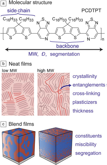
In contrast to small molecules, polymers have covalently bonded molecular units that typically extend significantly along one direction. This feature alone is a major contributor to the mechanical response in solid polymer films. Here, we review key molecular features and their related film morphology that impacts mechanical and electronic behavior, as illustrated in Figure 1a–b.
Schematic of the principal features that impact the mechanical and electronic properties of organic electronics, including (a) molecular structure (MW, molecular weight; Đ, dispersity), with an example shown of the polymer poly[N- 9′-heptadecanyl-2,7-carbazole-alt-5,5-(4,7-di-2-thienyl-2′,1′,3′-benzothiadiazole)] (PCDTPT), Reference Scott, Xue, Wang, Kline, Hoffman, Dougherty, Zhou, Bazan and O’Connor41 (b) neat film morphology, and (c) blend film morphology. Important blend films features include the materials, miscibility of the constituents, and lateral and vertical segregation behavior.

To start, the molecular weight (MW) of conjugated polymers fundamentally impacts mechanical and electronic properties. An increase in molecular weight results in the formation of polymer entanglements and interaggregate molecular tie chains, as illustrated in Figure 1b, that will act as hindrances to chain pullout under an applied stress, making the film tougher and increasing ductility. Reference Bruner and Dauskardt10,Reference Virkar, Mannsfeld, Bao and Stingelin13 From an electronic perspective, the increased interaggregate molecular coupling can reduce barriers to charge transport, improving carrier mobility. Reference Virkar, Mannsfeld, Bao and Stingelin13 Thus, increasing MW is generally favorable from both mechanical and electronic perspectives.
Regarding the molecular structure, most actively researched conjugated polymers have a conjugated ring structure along the backbone, making them characteristically semiflexible to rigid. Reference Venkateshvaran, Nikolka, Sadhanala, Lemaur, Zelazny, Kepa, Hurhangee, Kronemeijer, Pecunia, Nasrallah, Romanov, Broch, McCulloch, Emin, Olivier, Cornil, Beljonne and Sirringhaus7,Reference Virkar, Mannsfeld, Bao and Stingelin13–Reference Tummala, Risko, Bruner, Dauskardt and Bredas15 Recently, there has been a significant focus on copolymers with an electron donating subunit and electron accepting (DA) subunit along the backbone, where the subunits commonly have fused aromatic ring structures that can result in large persistence lengths (chain rigidity). This molecular approach provides the ability to tune electronic properties such as bandgap and has been shown to lead to improved charge mobility. Reference Liang, Xu, Xia, Tsai, Wu, Li, Ray and Yu16,Reference Sirringhaus17
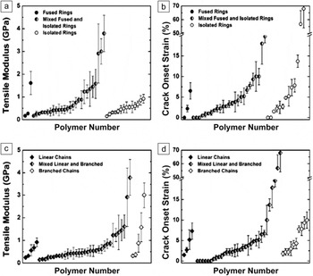
In a study of a large suite of DA polymers, increasing the fused ring nature along the backbone was correlated with stiffer films (E ≥ 1 GPa) and lower ductility (COS < 5%). Reference Roth, Savagatrup, de los Santos, Hagemann, Carle, Helgesen, Livi, Bundgaard, Sondergaard, Krebs and Lipomi18 However, the DA structure does not necessarily result in rigid-rod characteristics, Reference Venkateshvaran, Nikolka, Sadhanala, Lemaur, Zelazny, Kepa, Hurhangee, Kronemeijer, Pecunia, Nasrallah, Romanov, Broch, McCulloch, Emin, Olivier, Cornil, Beljonne and Sirringhaus7 and the mechanical behavior of films can vary widely, as shown in Figure 2 . The variation in mechanical properties was partly attributed to differences in film morphology, which must be taken into consideration to accurately capture the mechanical response of the film. Clearly, these results highlight that DA polymers can have widely varying mechanical properties and continued research is needed to accurately correlate DA backbone structure to film stiffness and ductility.
The tensile modulus and crack onset strain for a large library of donor–acceptor polymers with various structural features, categorized by (a–b) backbone and (c–d) side-chain features. Polymer number represents unique polymers considered. Reproduced with permission from Reference Reference Roth, Savagatrup, de los Santos, Hagemann, Carle, Helgesen, Livi, Bundgaard, Sondergaard, Krebs and Lipomi18. © 2016 American Chemical Society.

In addition to the backbone, an important factor influencing the mechanics of conjugated polymers are the solubilizing aliphatic side chains. Reference O’Connor, Chan, Chan, Conrad, Richter, Kline, Heeney, McCulloch, Soles and DeLongchamp19 In polymers where the side chains interdigitate, such as poly(2,5-bis(3-tetradecylthiophen-2-yl)thieno[3,2-b]thiophene) (PBTTT), films have been found to be brittle. Reference O’Connor, Chan, Chan, Conrad, Richter, Kline, Heeney, McCulloch, Soles and DeLongchamp19 However, in most conjugated polymers, the side chains are highly disordered and only weakly interact with other chains. Their placement along the backbone, size, and branching character all influence the polymer conformation and intermolecular packing character, subsequently impacting charge transport and mechanical behavior (Figure 2c–d). Savagatrup et al. conducted a well-controlled study of poly(3-alkylthiophenes) P3ATs, varying the side-chain length from 4-carbon units (butyl) to 12 (dodecyl), showing a significant drop in elastic modulus and increase in ductility for side chains of 7-carbon units (heptyl) and longer. This coincided with a drop in the glass-transition temperature, Reference Savagatrup, Makaram, Burke and Lipomi20,Reference Savagatrup, Printz, Wu, Rajan, Sawyer, Zaretski, Bettinger and Lipomi21 attributed to a relative decrease in the density of the load-bearing backbone. The increase in side-chain length of the polymers was accompanied by a drop in charge mobility when applied in an organic thin-film transistor (OTFT), but performance of poly(3-heptylthiophene) (P3HpT) was similar to the widely employed poly(3-hexylthiophene) (P3HT) when applied in an organic solar cell. Reference Savagatrup, Printz, Wu, Rajan, Sawyer, Zaretski, Bettinger and Lipomi21
It has also been shown that adding segmental variations along the polymer is an effective approach to modify the mechanical response of the film. The segmental variation can include modification to the backbone or side-chain structure. Reference Savagatrup, Printz, Rodriquez and Lipomi22–Reference Smith, Wright, Arnold, Sauvé, McCullough and Sydlik25 The variation likely increases disorder in the film, but may be tuned to find an optimized balance of mechanical and electronic properties. Reference Savagatrup, Printz, Rodriquez and Lipomi22 An extension of the segmental variation is to form cross-linked polymer networks using segmented polymers with repeat units that act as cross-linking agents. Reference Wang, Shaw, Xu, Kurosawa, Schroeder, Oh, Benight and Bao26,Reference Oh, Rondeau-Gagné, Chiu, Chortos, Lissel, Wang, Schroeder, Kurosawa, Lopez, Katsumata, Xu, Zhu, Gu, Bae, Kim, Jin, Chung, Tok and Bao27 There has been a demonstration of adding cross-linking side-chain moieties in a DA copolymer structure, showing significantly improved ductility compared to its uncross-linked counterpart and reversible stretchability (i.e., cyclically applied strain) over a 20% strain range when applied in an OTFT. Reference Wang, Shaw, Xu, Kurosawa, Schroeder, Oh, Benight and Bao26 It has also been recently reported that segmentation of nonconjugated units along the backbone that act as dynamic noncovalent cross-linking units can be used to achieve large COS of over 100% and stable high charge mobility (>0.7 cm2 V–1 s–1) over a 100% cyclic strain range. Reference Oh, Rondeau-Gagné, Chiu, Chortos, Lissel, Wang, Schroeder, Kurosawa, Lopez, Katsumata, Xu, Zhu, Gu, Bae, Kim, Jin, Chung, Tok and Bao27 The noncovalent cross-linking bonds are able to break under large strain, making the films tolerant to high strains without fracture. Similar copolymer strategies are discussed further in the text.
In addition to molecular structure, the film thickness can also contribute to mechanical behavior. A decrease in thickness can correlate with an increase in yield strain and crack onset strain. Reference Stafford, Vogt, Harrison, Julthongpiput and Huang28,Reference Printz, Zaretski, Savagatrup, Chiang and Lipomi29 Finally, plasticizers can be used to modify mechanical behavior of films as widely done in commodity polymers. While plasticizers can disrupt polymer packing, which may lead to decreased electrical performance, this approach has been successful at improving the ductility of poly(3,4-ethylenedioxythiophene) poly(styrene sulfonate) (PEDOT:PSS) films while not being detrimental to electrical conductivity. Reference Lipomi, Lee, Vosgueritchian, Tee, Bolander and Bao30–Reference Oh, Kim, Baik and Jeong33
Blend films and copolymer considerations
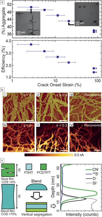
Polymer blends are widely used in organic electronics, including organic solar cells and OTFTs, and their mechanical behavior can be driven by a number of features, as listed in Figure 1c. We start by considering organic solar cells, where blending is the most prevalent. The most common material system is a conjugated polymer blended with a fullerene to form a bulk heterojunction (BHJ). Fullerene films are typically stiff and brittle with an elastic modulus of ∼3 GPa and crack onset strain below 3%. Reference Awartani, Lemanski, Ro, Richter, DeLongchamp and O’Connor34 Generally, mixing a polymer with fullerene will increase the stiffness, reduce film ductility, and decrease fracture energy of the film. Reference Roth, Savagatrup, de los Santos, Hagemann, Carle, Helgesen, Livi, Bundgaard, Sondergaard, Krebs and Lipomi18,Reference Awartani, Lemanski, Ro, Richter, DeLongchamp and O’Connor34,Reference Dupont, Oliver, Krebs and Dauskardt35 The relative change in mechanical properties of a polymer film when adding [6,6]-phenyl-C61-butyric acid methyl ester (PCBM) can vary depending on the polymer, Reference Roth, Savagatrup, de los Santos, Hagemann, Carle, Helgesen, Livi, Bundgaard, Sondergaard, Krebs and Lipomi18,Reference Awartani, Lemanski, Ro, Richter, DeLongchamp and O’Connor34,Reference Lipomi, Chong, Vosgueritchian, Mei and Bao36 suggesting that local molecular interactions and film morphology play a significant role in the mechanical behavior. This was highlighted in a study on P3HT:PCBM films, where local P3HT order was shown to impact film stiffness and ductility. Reference Awartani, Lemanski, Ro, Richter, DeLongchamp and O’Connor34 Disordered P3HT:PCBM films were characteristically ductile with COS over 75%. Processing strategies to promote P3HT aggregation, and increase efficiency of the solar cells, resulted in an increase in film stiffness and reduction in ductility, as shown in Figure 3a. This was attributed to reduced P3HT chain mobility in the mixed amorphous region. Reference Awartani, Lemanski, Ro, Richter, DeLongchamp and O’Connor34
(a) The crack onset strain of poly(3-hexylthiophene) [6,6]-phenyl-C61-butyric acid methyl ester (P3HT:PCBM) films with variation in local order as measured by percent P3HT aggregation, and the associated solar-cell power-conversion efficiency. Inset, images of cracks in the films at the specified strain. Reference Awartani, Lemanski, Ro, Richter, DeLongchamp and O’Connor34 (b) Atomic force microscope images of a P3HT:polystyrene-polyethylene/butylene-polystyrene composite showing segregated P3HT fibrils for 0% strain (i,iv), 30% tensile strain (ii,v), and recovered to unstrained state, (iii) phase image and (vi) conductivity. Scale bar is 500 nm. Reproduced with permission from Reference Reference Kim, Kim, Kang, Lee, Kang, Shin, Wang, Ma, Jeong, Kim and Kim38. © 2015 Wiley. (c) An illustration of the difference in crack onset strain (COS) between neat poly[N-9′-heptadecanyl-2,7-carbazole-alt-5,5-(4,7-di-2-thienyl-2′,1′,3′-benzothiadiazole)] (PCDTPT) and P3HT:PCDTPT blend films (ε, strain), and the secondary ion mass spectroscopy depth profile of the PCDTPT (measured through CN–) indicating its vertical segregation to the film surfaces. Reference Tummala, Bruner, Risko, Brédas and Dauskardt37

Replacing PCBM with indene-C60-mono adduct (ICMA) was shown to improve fracture energy, which was attributed to stronger molecular interactions. Reference Tummala, Bruner, Risko, Brédas and Dauskardt37 Replacing fullerenes with alternative small molecule or polymer acceptors is an attractive approach to improve both mechanical and electronic properties. Reference Kim, Kim, Kang, Lee, Kang, Shin, Wang, Ma, Jeong, Kim and Kim38 A high-performance all-polymer blend film was recently demonstrated to have significantly improved mechanical properties compared to its polymer:fullerene counterpart, in terms of toughness, ductility, and bending stability. Reference Kim, Kim, Kang, Lee, Kang, Shin, Wang, Ma, Jeong, Kim and Kim38 This was attributed to well-intermixed polymer domains with significant entanglements of both polymers.
In OTFTs, secondary polymers have been blended with the primary semiconductor to improve mechanical behavior, including improvements in ductility, yield strength, and elongation at break. Reference Moulton and Smith39–Reference Scott, Xue, Wang, Kline, Hoffman, Dougherty, Zhou, Bazan and O’Connor41 Examples include blending commodity polymers such as high-density polyethylene with doped polythiophene to achieve highly ductile films that remained electrically conductive. Reference Moulton and Smith39 With the goal of reversible stretchability, conjugated polymers have also been blended with elastomers. Reference Shin, Oh, Byun, Lee, Kim, Baik, Park and Jeong42–Reference Song, Kang, Choi, Sin, Lee, Lee and Cho44 In this approach, processing methods are used to promote segregation of the polymer semiconductor to form a fibril network within the elastomer host. Vertical segregation of the fibrils to the surface of the film then enables efficient charge transport in an OTFT (example shown in Figure 3b). This has been primarily achieved for P3HT embedded in polystyrene-polyethylene/butylene-polystyrene (SEBS), Reference Shin, Oh, Byun, Lee, Kim, Baik, Park and Jeong42 or poly(dimethylsiloxane) elastomers. Reference Choi, Kim, Persson, Chu, Chang, Kang, Graham and Reichmanis43,Reference Song, Kang, Choi, Sin, Lee, Lee and Cho44 Under strain, the fibrils reorient in the direction of strain and the elastomer provides the restoring force upon strain removal. Reference Song, Kang, Choi, Sin, Lee, Lee and Cho44 At some point in the elongation process, fracture of the fibril network can occur, depending on the local strain on the fibrils and elasticity/plasticity of the fibrils. Reference Song, Kang, Choi, Sin, Lee, Lee and Cho44
Alternatively, two semiconducting polymers have been blended using a ductile polymer (high MW P3HT) with a high charge mobility but brittle DA polymer poly[N-9′-heptadecanyl-2,7-carbazole-alt-5,5-(4,7-di-2-thienyl-2′,1′,3′-benzothiadiazole)] (PCDTPT) to achieve films with increased ductility while maintaining high charge mobility. Reference Scott, Xue, Wang, Kline, Hoffman, Dougherty, Zhou, Bazan and O’Connor41 By casting a 1:4 wt% ratio of PCDTPT:P3HT, the crack onset strain increased from approximately 4% for neat PCDTPT to over 75%. Reference Scott, Xue, Wang, Kline, Hoffman, Dougherty, Zhou, Bazan and O’Connor41 It was found that vertical segregation of the polymers occurred such that the surface interfacing with the gate dielectric in an OTFT was PCDTPT-rich enabling high charge mobility (Figure 3c), yet significant intermixing throughout the film thickness was also present, thereby improving ductility.
The PCDTPT:P3HT blend was also recently shown to be reversibly stretchable, achieved through repeatable plastic deformation of the film in both tension in compression, resulting in stable charge mobility under cyclic strain of 65%. Reference Sun, Scott, Wang, Kline, Bazan and O’Connor45
Block copolymers are an alternative approach to combine polymer semiconductors with insulating polymers to improve mechanical properties. A block copolymer composed of P3HT and polyethylene (PE) was shown to increase film ductility and strength, while maintaining charge transport similar to neat P3HT films. Reference Muller, Goffri, Breiby, Andreasen, Chanzy, Janssen, Nielsen, Radano, Sirringhaus, Smith and Stingelin-Stutzmann40 Samples with P3HT as low as 10 wt% were shown to maintain charge-transport properties while having an elongation at break exceeding 600%. More recently, a triblock copolymer has also been demonstrated consisting of P3HT-poly(methylacrylate)-P3HT to form a thermoplastic elastomer, similar to the segmenting cross-linking approach previously discussed. The cast films could be stretched over 100%, but had limited charge mobility (<10–3 cm2 V–1 s–1). Reference Peng, Pang, Hu, Chen, Zhang, Wang, Lu, Cho and Qiu46
Microstructural changes upon stretching
Stretchable conductors can be defined as films that maintain functionality after a large change in shape. This definition is purposefully broad to include methods ranging from geometric approaches that allow a change in shape with minimal strain on the active layers to films that elastically or plastically deform under a stretching event, which can be singular or repeating. Reference Lipomi8 In this section, we focus on microstructural changes in conducting polymers under large nominal tensile strain while on an elastomer host.
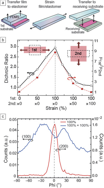
Straining the films while on an elastomer, as illustrated in Figure 4a, is a common approach to screen films for stretchability, and to capture changes in microstructure under strain. Reference Scott, Xue, Wang, Kline, Hoffman, Dougherty, Zhou, Bazan and O’Connor41–Reference Chortos, Lim, To, Vosgueritchian, Dusseault, Kim, Hwang and Bao49 Under large tensile strain, one of the first characteristics explored is the COS. Reference O’Connor, Chan, Chan, Conrad, Richter, Kline, Heeney, McCulloch, Soles and DeLongchamp19,Reference Savagatrup, Printz, O’Connor, Zaretski and Lipomi47 This is measured by monitoring for crack initiation using optical microscopy (or atomic force microscopy) under increasing applied strain.
(a) Illustration of the strain process, including picking the film up with an elastomer stamp from a donor substrate, straining the film while on the elastomer, and printing to a receiving substrate for subsequent processing or characterization. (b) Dichroic ratio of a poly(3-hexylthiophene) (P3HT) film with applied strain along two directions, along with the relative change in charge mobility (μ). The mobility is reported as the ratio of charge mobility parallel to the first strain direction (μ1st) to mobility in the transverse direction (μ2nd). (c) X-ray diffraction of a P3HT film after 100% uniaxial strain, and a film strained by 100% consecutively in transverse directions, as illustrated in the inset in (b). Reference Gargi, Kline, DeLongchamp, Fischer, Toney and O’Connor51 The dichroic ratio corresponds to the alignment of the polymer backbone in the plane of the film for both the amorphous and crystalline regions. The x-ray diffraction corresponds to the in-plane orientation distribution of crystallites with a specific out-of-plane orientation.

While cracking is typically undesirable, creating controlled fracture networks has been shown to be an effective approach to achieve stretchable transistors. Reference Wu, Benight, Chortos, Lee, Mei, To, Lu, He, Tok, Chen and Bao48,Reference Chortos, Lim, To, Vosgueritchian, Dusseault, Kim, Hwang and Bao49 In this approach, while the film is no longer continuous, there remains a pathway for charge to transport across the device to retain function. In this case, the cracks open to accommodate an applied tensile strain and the local polymer morphology is not expected to change significantly. For highly elastic or ductile conjugated polymer films under large tensile strains, the most striking morphology change is the alignment of the polymer backbone in the direction of strain. Reference Scott, Xue, Wang, Kline, Hoffman, Dougherty, Zhou, Bazan and O’Connor41,Reference O’Connor, Kline, Conrad, Richter, Gundlach, Toney and DeLongchamp50–Reference Yang, Lee and Heeger52 Given that in conjugated polymers, the primary optical transition dipole moment is typically along the polymer backbone, Reference Vezie, Few, Meager, Pieridou, Dorling, Ashraf, Goni, Bronstein, McCulloch, Hayes, Campoy-Quiles and Nelson14 the extent of chain alignment is captured by measuring the absorbance anisotropy under linear polarized light. Reference Scott, Xue, Wang, Kline, Hoffman, Dougherty, Zhou, Bazan and O’Connor41,Reference O’Connor, Kline, Conrad, Richter, Gundlach, Toney and DeLongchamp50 The average chain alignment with applied strain can then be quantified by determining the dichroic ratio of the film, as shown in Figure 4b. The absorbance of the film is also commonly used to capture the local order of conjugated polymers. By measuring changes in absorbance features under orthogonal linear polarizations, the changes in local order of the reoriented polymer can be captured. Reference O’Connor, Reid, Zhang, Kline, Richter, Gundlach, DeLongchamp, Toney, Kopidakis and Rumbles53,Reference Awartani, Zhao, Currie, Kline, Zikry and O’Connor54
To capture changes in the crystalline portion of the films, grazing incidence x-ray diffraction (GIXD) is commonly employed. Reference Scott, Xue, Wang, Kline, Hoffman, Dougherty, Zhou, Bazan and O’Connor41,Reference O’Connor, Kline, Conrad, Richter, Gundlach, Toney and DeLongchamp50,Reference Gargi, Kline, DeLongchamp, Fischer, Toney and O’Connor51 Two-dimensional-GIXD images provide insight into in-plane polymer alignment as well as changes in out-of-plane polymer stacking, which may occur with deformation. Reference Muller, Goffri, Breiby, Andreasen, Chanzy, Janssen, Nielsen, Radano, Sirringhaus, Smith and Stingelin-Stutzmann40,Reference Chortos, Lim, To, Vosgueritchian, Dusseault, Kim, Hwang and Bao49 To quantify the in-plane orientation distribution of the crystallites, azimuthal rotation of the film with respect to the x-ray beam (i.e., a phi-scan) is necessary, with an example shown in Figure 4c. Reference O’Connor, Kline, Conrad, Richter, Gundlach, Toney and DeLongchamp50,Reference Gargi, Kline, DeLongchamp, Fischer, Toney and O’Connor51 By contrasting the in-plane crystal orientation distribution with the absorbance anisotropy, the relative alignment of crystalline and amorphous components of the film can be approximated. Reference O’Connor, Kline, Conrad, Richter, Gundlach, Toney and DeLongchamp50 For example, in uniaxial strain-oriented P3HT films, the crystallites were found to strongly orient in the direction of strain, whereas the amorphous polymer had a weaker but net in-plane orientation. Reference O’Connor, Kline, Conrad, Richter, Gundlach, Toney and DeLongchamp50 The combined absorbance and GIXD approach has also been used to show that in P3HT films strained 100% successively in transverse directions, the oriented chains that form under uniaxial strain move back toward an in-plane isotropic distribution, as shown in Figure 4b–c. Reference Gargi, Kline, DeLongchamp, Fischer, Toney and O’Connor51 This rearrangement is consistent with reversibly stretchable demonstrations of polymer semiconductor blends, Reference Sun, Scott, Wang, Kline, Bazan and O’Connor45 and cross-linked polymer semiconductors. Reference Oh, Rondeau-Gagné, Chiu, Chortos, Lissel, Wang, Schroeder, Kurosawa, Lopez, Katsumata, Xu, Zhu, Gu, Bae, Kim, Jin, Chung, Tok and Bao27 Note that transmission electron microscopy (TEM) methods have also been used to capture the polymer crystalline orientation distribution, and in polymers with large-ordered domains, TEM can be used to map the orientation distribution in strained films. Reference Yang, Lee and Heeger52,Reference Xue, Chandler, Zhang, Kline, Fei, Heeney, Diemer, Jurchescu and O’Connor55
In terms of electrical properties, charge transport along the polymer backbone is generally favored over intermolecular transport paths. In uniaxial strain-oriented films, charge mobility can thus be improved in the direction of polymer chain alignment. Reference Scott, Xue, Wang, Kline, Hoffman, Dougherty, Zhou, Bazan and O’Connor41,Reference O’Connor, Kline, Conrad, Richter, Gundlach, Toney and DeLongchamp50,Reference Gargi, Kline, DeLongchamp, Fischer, Toney and O’Connor51 However, there are conflicting reports on the change in mobility in strain-oriented films, and details of local molecular packing modification need to be considered. Reference Oh, Rondeau-Gagné, Chiu, Chortos, Lissel, Wang, Schroeder, Kurosawa, Lopez, Katsumata, Xu, Zhu, Gu, Bae, Kim, Jin, Chung, Tok and Bao27,Reference Wu, Benight, Chortos, Lee, Mei, To, Lu, He, Tok, Chen and Bao48 One common observation is that as the channel length of the OTFT increases, improvements in charge mobility with chain alignment are less significant, suggesting that barriers to charge transport across μm length scales may be present. Reference Scott, Xue, Wang, Kline, Hoffman, Dougherty, Zhou, Bazan and O’Connor41,Reference Xue, Chandler, Zhang, Kline, Fei, Heeney, Diemer, Jurchescu and O’Connor55
In applications that require reversible stretching that result in polymer deformation, it will be necessary to account for the variation in charge mobility, Reference Oh, Rondeau-Gagné, Chiu, Chortos, Lissel, Wang, Schroeder, Kurosawa, Lopez, Katsumata, Xu, Zhu, Gu, Bae, Kim, Jin, Chung, Tok and Bao27,Reference Sun, Scott, Wang, Kline, Bazan and O’Connor45 along with changes in device dimensions, Reference Oh, Rondeau-Gagné, Chiu, Chortos, Lissel, Wang, Schroeder, Kurosawa, Lopez, Katsumata, Xu, Zhu, Gu, Bae, Kim, Jin, Chung, Tok and Bao27 and resulting mechanical anisotropy. Reference Awartani, Zhao, Currie, Kline, Zikry and O’Connor54 In the P3HT film deformed along multiple axes, it was found that the charge mobility in an OTFT tracks well with the change in polymer backbone alignment throughout the straining process as shown in Figure 4b. Reference Peng, Pang, Hu, Chen, Zhang, Wang, Lu, Cho and Qiu46 Similarly, the charge mobility has been shown to track well with backbone orientation in demonstrations of cyclically stretched films. Reference Oh, Rondeau-Gagné, Chiu, Chortos, Lissel, Wang, Schroeder, Kurosawa, Lopez, Katsumata, Xu, Zhu, Gu, Bae, Kim, Jin, Chung, Tok and Bao27,Reference Sun, Scott, Wang, Kline, Bazan and O’Connor45
Lastly, it is important to mention computational efforts to gain insight into the mechanical behavior of organic electronic film. Reference Tummala, Risko, Bruner, Dauskardt and Bredas15,Reference Tummala, Bruner, Risko, Brédas and Dauskardt37,Reference Zhao, Awartani, O’Connor and Zikry56,Reference Root, Savagatrup, Pais, Arya and Lipomi57 These efforts include modeling at broad length scales, including atomistic molecular dynamics (MD) simulations, Reference Tummala, Risko, Bruner, Dauskardt and Bredas15,Reference Tummala, Bruner, Risko, Brédas and Dauskardt37 coarse-grained MD, Reference Root, Savagatrup, Pais, Arya and Lipomi57 and microstructural finite element methods. Reference Zhao, Awartani, O’Connor and Zikry56 A number of important features have been effectively modeled, including film stiffness, Reference Root, Savagatrup, Pais, Arya and Lipomi57 the role of entanglements on toughness, Reference Tummala, Risko, Bruner, Dauskardt and Bredas15 and the role of crystallinity on COS. Reference Zhao, Awartani, O’Connor and Zikry56 Continued computational efforts will surely assist in moving this emerging field forward.
Conclusions
Organic conductors have inherent properties that make them a highly attractive material system to realize high-performance flexible and stretchable electronics. This includes the vast design space in materials synthesis and directed multicomponent film morphology. Over the past five years, there has been increased emphasis on capturing the mechanical behavior of organic electronics to achieve physically robust flexible and stretchable organic electronics. This article has only highlighted some of the many efforts focused around establishing the role of film morphology on mechanical and electronic properties.
Through this research, molecular and morphological approaches to achieve mechanically and electronically optimized films are starting to emerge. This includes capturing the temporal morphology characteristics that are needed for films that are no longer expected to be nominally static. While significant progress has been made, continued research is necessary to accurately capture the role of morphology on mechanical behavior and to guide future material design strategies.
Acknowledgments
The authors would like to acknowledge the National Science Foundation Grants CMMI-1200340, and CMMI-1554322; and the UNC-GA Research Opportunity Initiative Grant for research support on this topic and motivation for this review.

Brendan T. O’Connor is an assistant professor at North Carolina State University in the Mechanical and Aerospace Engineering Department. He received his PhD degree in mechanical engineering from the University of Michigan. He was then a National Research Council postdoctoral research fellow at the National Institute of Standards and Technology in the polymers division. He is a recent recipient of an NSF CAREER Award to study the mechanical behavior of organic electronics. O’Connor can be reached by phone at 919-515-5282 or by email at btoconno@ncsu.edu.

Omar M. Awartani is a postdoctoral research associate in the Department of Physics at North Carolina State University. He earned his PhD degree in mechanical engineering in 2015 from North Carolina State University. His current research focuses on understanding the complex correlations between morphology (using several synchrotron-based x-ray techniques), optoelectronic properties, and device performance of organic solar cells to guide future design of superior electronic materials. Awartani can be reached by email at omawarta@ncsu.edu.

Nrup Balar is a doctoral student in the Department of Mechanical and Aerospace Engineering at North Carolina State University. He earned his bachelor’s degree in mechanical engineering from the National Institute of Technology Calicut, India, and his MS degree in mechanical engineering from North Carolina State University in 2016. His current research focuses on studying mechanical properties of semiconducting polymers, which will drive the mechanical stability of flexible and stretchable organic solar cells and transistors. Balar can be reached by email at nlbalar@ncsu.edu.