I. INTRODUCTION
In wireless communication systems, the involvement of multiple antenna at both the transmitter and receiver i.e. multiple input multiple output (MIMO) systems is used to significantly increase the channel capacity. Recently, ultrawideband (UWB) systems are used for high speed low power data communication. However, UWB technology faces severe challenges such as multipath fading. This challenge can be overcome by using UWB MIMO systems. UWB MIMO system employs multiple antennas in a smaller area for portable applications. The high isolation among the antenna elements is a basic requirement for good diversity performance. Several UWB MIMO antennas are proposed in the literature [Reference Lee, Kim, Ryu and Woo1–Reference Koohestani, Moreira and Skrivervik4]. The UWB MIMO antenna discussed in [Reference Lee, Kim, Ryu and Woo1] uses the meander lines to enhance the isolation between the antenna elements. Nevertheless, this will increase the system dimensions and its complexity. In [Reference Gao, He, Wei, Xu, Wang and Zheng2, Reference Chacko, Augustin and Denidni3], uniplanar UWB MIMO antennas are presented having rectangular strip for isolation enhancement between the antenna elements. In [Reference Koohestani, Moreira and Skrivervik4], UWB MIMO antenna is realized without any decoupling network by simply using the orthogonal orientation of antenna elements for good isolation. However, the size of antenna presented in [Reference Koohestani, Moreira and Skrivervik4] is quite large. Thus, designing a UWB MIMO antenna with compact size and good isolation is a challenging task.
In this paper, a uniplanar UWB MIMO antenna is presented. The presented antenna can be used for wireless personal area network (WPAN), wireless body area network (WBAN) and other applications which operates in FCC specified UWB spectrum, wherever there is a problem of multipath fading. This MIMO antenna has single common circular radiator for both the antenna elements. These antenna elements are fed by two tapered CPW feeding structures. The isolation between them is achieved by introducing a rectangular slot in the common radiator. In Section II, the geometry of the proposed antenna is explained in detail. The parametric analysis of the antenna design parameters are presented in Section III. The simulated and measured results are presented in Section IV in order to verify the present approach. Finally, a comparison has been made with the existing state of art UWB MIMO/diversity antennas for the above applications.
II. ANTENNA CONFIGURATION
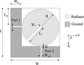
The configuration of the proposed 2 × 2 UWB MIMO antenna is shown in Fig. 1. The proposed antenna is designed on inexpensive FR4 substrate of dielectric constant 4.4, loss tangent 0.02 and thickness 0.8 mm. The size of the proposed UWB MIMO antenna is 45 × 45 mm2. The radiating element is common circular radiator for both the UWB antennas. This common radiator is fed by two tapered CPW structures and is designated as Port 1 and Port 2. The dual polarization is achieved by two simple orthogonally oriented feeds. The single common radiator helps to reduce the overall size of the UWB MIMO antenna. The UWB MIMO antenna has an L-shaped ground plane present on the same side of the substrate.
Configuration of the proposed UWB MIMO antenna.

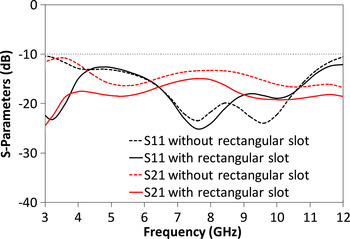
The simulated impedance bandwidth of the antenna is 3–12 GHz which covers the overall UWB spectrum. It has three resonant frequencies. The isolation between the two antenna elements of MIMO structure is 11 dB (lower band of frequencies of UWB spectrum) without rectangular slot in the radiator as shown in Fig. 2. However, for good diversity performance the isolation must be better than 15 dB [Reference Gao, He, Wei, Xu, Wang and Zheng2, Reference Zhang, Ying, Xiong and He5] in the entire UWB spectrum. High isolation (≥15 dB) between the antenna elements is achieved by creating a rectangular slot of dimensions L 1 × W 1 in the common radiator at an angle of ϕ = 45° (Fig. 2).
S-parameters of UWB MIMO antenna without rectangular slot and with rectangular slot in the common radiator.

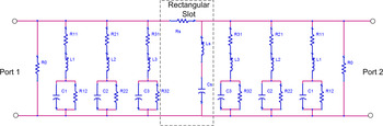
Figure 3 represents the symbolic equivalent circuit of the proposed UWB MIMO antenna. The multiple resonances in the reflection coefficient of single UWB antenna can be modeled as parallel combination of R-L-C circuit shown in Fig. 3. The rectangular slot is introduced in the circular radiator to enhance the isolation between the two ports of the UWB MIMO antenna. This quarter wavelength long rectangular slot creates a resonance at 3.1 GHz, which in turn results in low mutual coupling between the two ports. The rectangular slot can be modeled as a combination of Rs-Ls-Cs as shown in Fig. 3.
Symbolic equivalent circuit of the proposed UWB MIMO antenna.

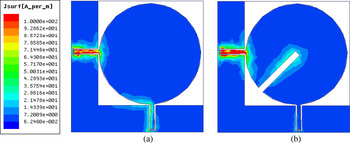
The isolation enhancement phenomenon can be better explained in terms of surface current distributions. Figure 4(a) shows the surface current distribution at 3.1 GHz if Port 1 is excited and Port 2 is terminated with matched load of 50 Ω. When the Port 1 is excited then there is some amount of surface current present at port 2 through the common radiator and the ground plane. In order to reduce this surface current present at Port 2, a rectangular slot is introduced in the common radiator as shown in Fig. 4(b). The surface currents are mainly confined in the rectangular slot at 3.1 GHz, which thereby significantly reduce the mutual coupling between the two ports.
Surface current distribution of UWB MIMO antenna at 3.1 GHz (a) without rectangular slot (b) with rectangular slot in the common radiator.

III. PARAMETRIC ANALYSIS OF ANTENNA DESIGN PARAMETERS
A parametric analysis is performed for different design parameters to obtain the desired antenna performance.
A) Effect of R
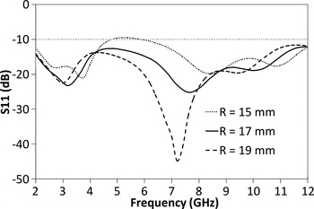
The simulated S 11 parameters for different values of R (radius of UWB MIMO antenna) are shown in Fig. 5. As the value of R increases from 15 to 19 mm, in steps of 2 mm, the S 11 characteristics gets improved at the expense of overall size of the antenna. Thus, R = 17 mm is chosen as an optimum design parameter with acceptable S 11 characteristics.
Simulated S 11 parameters for different values of R of the proposed UWB MIMO antenna.

B) Effect of W g
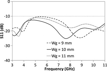
The simulated S 11 parameters for different values of W g (ground plane width) are shown in Fig. 6. It is clear from the figure, for W g = 10 mm, S 11 parameter is well below −10 dB for the entire UWB spectrum. Hence, W g = 10 mm is chosen as optimized design parameter.
Simulated S 11 parameters for different values of W g of the proposed UWB MIMO antenna.

C) Effect of g
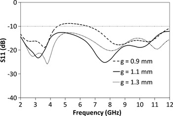
The gap between the circular radiator and the ground plane is also a critical parameter hence its parametric study is required for UWB antenna design. For g = 1.1 mm and g = 1.3 mm, the S 11 parameter is below −10 dB which ensures good radiation performance as shown in Fig. 7. Thus, for compact size and good antenna performance, g = 1.1 mm is chosen as antenna design parameters.
Simulated S 11 parameters for different values of g of the proposed UWB MIMO antenna.

D) Effect of L 1 and W 1
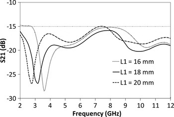
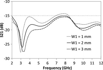
The parametric analysis for different lengths of the rectangular slot is depicted in Fig. 8. The isolation (S 21) is better than 15 dB for all the three values of L 1. But, for L 1 = 18 mm, the isolation is better than 17 dB for the entire UWB spectrum. Also, the parametric study has been performed for different widths of the rectangular slot. As can be seen from Fig. 9, W 1 = 2 mm provides isolation better than 17 dB for the whole UWB spectrum. Hence, L 1 = 18 mm and W 1 = 2 mm are chosen as an optimum design parameters of the rectangular slot.
Simulated S 11 parameters for different values of L 1 of the proposed UWB MIMO antenna.

Simulated S 11 parameters for different values of W 1 of the proposed UWB MIMO antenna.

The final optimized dimensions of the proposed UWB MIMO antenna are as follows: L = 45 mm, W = 45 mm, R = 17 mm, g = 1.1 mm, L g = 16 mm, W g = 10 mm, L 1 = 18 mm, W 1 = 2 mm, W ms = 1.5 mm, s = 0.3 mm.
IV. RESULTS AND DISCUSSIONS
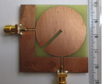
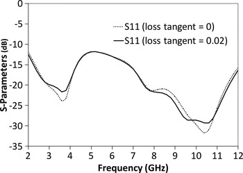
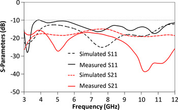
The proposed UWB MIMO antenna is fabricated on low cost FR4 substrate as shown in Fig. 10 in order to verify the present approach of antenna design. This designed antenna is measured on Agilent VNA E5071C. The size of the UWB MIMO antenna is 45 × 45 mm2. Figure 11 shows the simulated return loss characteristics with tangent loss of 0.02 and 0. It can be observed from Fig. 11 that the loss of the UWB antenna with loss tangent of 0 is lower than that of 0.02 inevitably at the higher frequencies. The substrate dielectric loss reduces the port reflection coefficient especially at higher frequencies (above 8 GHz), it is due to the fact large amount of energy gets lost in the lossy dielectric substrate. Figure 12 shows simulated and measured S-parameters of the fabricated UWB MIMO antenna. The simulated impedance bandwidth is 3–12 GHz which covers the whole UWB spectrum. The simulated S 21 is well below −17 dB for the UWB bandwidth. From Fig. 12, it is clear that the measured impedance bandwidth is from 3 to 12 GHz. The measured isolation is better than 17 dB for the whole UWB spectrum. There is a good agreement between the measured and simulated results. However, there are some disparities, which can be attributed to SMA connector losses, fabrication tolerances, measuring environment, etc. which are not considered during the simulations.
Photograph of the fabricated UWB MIMO antenna.

Simulated S 11 parameters for different values of loss tangent of FR4 substrate for proposed UWB MIMO antenna.

Simulated and measured S-parameters of UWB MIMO antenna.

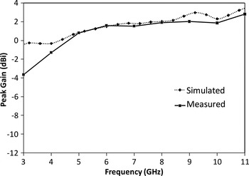
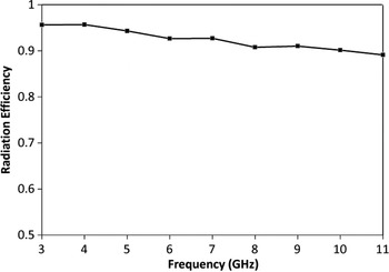
Figure 13 shows the simulated and measured peak gain of the proposed UWB MIMO antenna. The peak gain is nearly constant for the entire UWB frequency band except for the lower frequencies. Figure 14 shows the simulated radiation efficiency of the proposed antenna. It can be observed from figure that the simulated radiation efficiency of the proposed UWB MIMO antenna are very high in lower and middle band of UWB spectrum, but it decreases at higher frequencies of UWB spectrum. The reduction in simulated radiation efficiency at higher frequencies can be due to finite loss tangent (tan δ = 0.02) of FR4 substrate.
Simulated and measured peak gain of UWB MIMO antenna.

Radiation efficiency of UWB MIMO antenna.

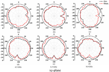
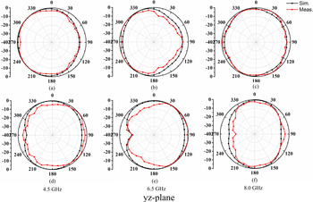
Figures 15 and 16 shows the simulated and measured radiation patterns of the proposed UWB MIMO antenna in xy- and yz-plane at three resonant frequencies (4.5, 6.5, and 8 GHz), respectively. Figures 15(a)–15(c) shows the radiation pattern if Port 1 is excited and Port 2 is terminated with matched load, whereas Figs 15(d)–15(f) shows the radiation pattern if Port 2 is excited and Port 1 is terminated with matched load in xy-plane. It is clear from the figure that the two antenna elements in the proposed UWB MIMO antenna have orthogonal radiation pattern. Figure 16 depicts that the radiation patterns of both the antenna elements in yz-plane are nearly omni-directional.
Simulated and measured radiation pattern of UWB MIMO antenna in xy-plane. Port 1 is excited at (a) 4.5 GHz, (b) 6.5 GHz, and (c) 8 GHz and port 2 is excited at (a) 4.5 GHz, (b) 6.5 GHz, and (c) 8 GHz (other port is terminated with matched load).

Simulated and measured radiation pattern of UWB MIMO antenna in yz-plane. Port 1 is excited at (a) 4.5 GHz, (b) 6.5 GHz, and (c) 8 GHz and port 2 is excited at (a) 4.5 GHz, (b) 6.5 GHz, and (c) 8 GHz (other port is terminated with matched load).

Envelope correlation coefficient (ECC) and channel capacity loss (CCL) are the major parameters which characterize the diversity performance of a UWB MIMO antenna. The ECC can be defined in terms of S-parameters as follows [Reference Blanch, Romeu and Corbella6]:
 $${\rm \rho} _e = \displaystyle{{ \vert S_{11}^\ast S_{12} + S_{21}^\ast S_{22} \vert ^2} \over {(1 - \vert S_{11} \vert ^2 - \vert S_{21} \vert ^2 )(1 - \vert S_{22} \vert ^2 - \vert S_{12} \vert ^2 )}}.$$
Figure 17 shows the simulated and measured ECC performance of the proposed UWB MIMO antenna. Both of them are below their acceptable limit of 0.5 [Reference Li, Chu, Li and Xia7], which depicts that there is very low mutual coupling between the MIMO antenna elements.
Simulated and measured ECC of UWB MIMO antenna.

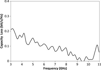
Along with ECC, the CCL (b/s/Hz) is also a vital parameter that influences the quality of MIMO antenna. It is the upper limit of information rate at which reliable communications happen over the channel. For good MIMO performance, it must be within the acceptable limit of 0.4 b/s/Hz [Reference Li, Chu and Huang8, Reference Shin and Lee9]. It is calculated with the use of correlation matrix defined in [Reference Valderas, Crespo and Ling10] and is expressed as follows:
 $$CL_{loss} = - \log _2 \det ({\rm \Psi} _R ),$$
where Ψ R is the correlation matrix of receiving antenna and the elements ρ ij are the correlation coefficients and defined as follows:
 $$\rho _{ii} = 1 - \vert S_{ii} \vert ^2 - \vert S_{ij} \vert ^2 \,{\rm and}$$
 $$\rho _{ij} = - (S_{ii}^\ast S_{ij} + S_{ji}^\ast S_{jj} )\,{\rm for}\,i,{\rm} j\, = \,1\,{\rm or}\,2.$$
Figure 18 shows the measured CCL of UWB MIMO antenna and it is well below the limit of 0.4 b/s/Hz for the entire UWB spectrum.
Measured CCL of UWB MIMO antenna.

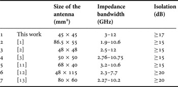
In Table 1, a comparison has been presented with the existing UWB MIMO/diversity antenna. It is clear from the table that the proposed UWB MIMO antenna has the compact dimensions, wide impedance bandwidth along with good isolation than the antennas reported in the references.
Comparison of UWB MIMO/diversity antennas.

V. CONCLUSION
In this paper, a 2 × 2 UWB MIMO antenna having common radiator is presented. The common radiator is circular shaped and is fed by two orthogonally oriented tapered CPW structures. In order to have better isolation between the antenna elements, a rectangular slot is introduced in the circular radiator. The proposed MIMO antenna have the measured impedance bandwidth of 3–12 GHz with the isolation better than 17 dB for the entire UWB spectrum. To get better insight of antenna performance, a parametric analysis of different antenna design parameters is performed. The proposed antenna is fabricated, and measured in order to verify the present approach. The radiation pattern of the UWB MIMO antenna is measured in xy- and yz-plane. The measured results are in good agreement with the simulated results. The detailed investigation of diversity performance in terms of ECC and capacity loss is presented in this paper. Both of them are within their acceptable limits, which make it suitable candidate for WPAN and WBAN applications.
 Garima Srivastava received her B.Tech. degree in Electronics Engineering from the University of Allahabad in 2000 and M.Tech. degree in Communication Engineering in 2002. Presently, she is working as Assistant Professor in Ambedkar Institute of Technology (AIT) Govt. of N.C.T. Delhi and is also working towards her Ph.D. degree. Her research interests are in UWB antennas and planar antennas.
 Binod Kumar Kanaujia is presently working as Associate Professor in the Department of Electronics & Communication Engineering in Ambedkar Institute of Advanced Communication Technologies & Research (formerly Ambedkar Institute of Technology), Geeta Colony, Delhi. Dr., Kanaujia joined this institute as Assistant Professor in 2008 through selection by Union Public Service Commission, New Delhi, India and served on various key portfolios i.e. Head of Department, In-charge Central Library, Head of Office, etc. Before joining this institute he served in the M.J.P. Rohilkhand University, Bareilly, India as Reader in the Department of Electronics & Communication Engineering and also as Head of the Department. He has been an active member of Academic Council and Executive Council of the M.J.P. Rohilkhand University and played a vital role in academic reforms. Prior, to his career in academics, Dr., Kanaujia worked as Executive Engineer in the R&D division of M/s UPTRON India Ltd.
Dr., Kanaujia completed his B.Tech. in Electronics Engineering from KNIT Sultanpur, India in 1994. He did his M.Tech. and Ph.D. in 1998 and 2004, respectively, from Department of Electronics Engineering, Indian Institute of Technology Banaras Hindu University, Varanasi, India. He has been awarded Junior Research Fellowship by UGC Delhi in the year 2001–2002 for his outstanding work in electronics field. He has keen research interest in design and modeling of microstrip antenna, dielectric resonator antenna, left handed metamaterial microstrip antenna, shorted microstrip antenna, ultra wideband antennas, reconfigurable and circular polarized antenna for wireless communication.
He has been credited to publish more than 120 research papers with more than 280 citations with h-index of 10 in peer-reviewed journals and conferences. He has supervised 45 M.Tech. and three Ph.D. research scholars in the field of microwave engineering. He is a reviewer of several journals of international repute i.e. IET Microwaves, Antennas & Propagation, IEEE Antennas and Wireless Propagation Letters, Wireless Personal Communications, Journal of Electromagnetic Wave and Application, Indian Journal of Radio and Space Physics, IETE Technical Review, International Journal of Electronics, International Journal of Engineering Science, IEEE Transactions on Antennas and Propagation, AEU-International Journal of Electronics and Communication, International Journal of Microwave and Wireless Technologies, etc. Dr., Kanaujia has successfully executed four research projects sponsored by several agencies of Government of India i.e. DRDO, DST, AICTE, and ISRO. He is also a member of several academic and professional bodies i.e. IEEE, Institution of Engineers (India), Indian Society for Technical Education, and The Institute of Electronics and Telecommunication Engineers of India.
 Rajeev Paulus received his Ph.D. degree from the Department of Electronic & Communication Engineering, SHIATS, Allahabad, M.Tech. degree from the Department of Electrical Engineering MNNIT, Allahabad and Bachelor's degree from University of Pune. He has been working in the Department of Electronic & Communication Engineering, as an Assistant Professor in Sam Higginbotom Institute of Agriculture, Technology & Sciences since 2005. He is a member of IEEE, Life member of ISTE and many other professional bodies. He has published research papers in national and international journals and presented many papers in Conferences at both National and International Level. His main areas of interest are Data Communication Networking, Optical communication & network, Network Management, Cellular network (4G), Sensor & Mobile Adhoc-network.