


Specific Drill Fluid Requirements And Constraints
The SUBGLACIOR probe (in SitU proBing of GLACier Ice for a better understanding of the Orbital Response of climate) is being designed to drill down to 3500 m in a continuous run by electromechanical drilling and pumping the generated ice chips to the surface by circulating a drill fluid (Reference AlemanyAlemany and others, 2014). Three main elements of the probe are a drill head with melt-tip; a sample-handling system; and a laser spectrometer for in situ measurements.
The drill fluid will be pumped down a hose, through the probe and then ejected at the drill head to wash away the ice chips and carry them to the surface where they will be separated. The ice-chips transport is the primary reason for using a drill fluid and will require a leak-tight casing through the firn zone (Reference Duphil and PossentiDuphil and Possenti, 2014). Because of the complexity of this system and the large range of critical components continuously exposed to the fluid, suitable material compatibility is important. Furthermore, as the ice chips will be pumped past the probe, up the entire length of the borehole, the fluid should have minimal or no effect on the ice to avoid any clumping together of ice chips with subsequent risk of blocking the borehole with slush.
Meltwater and gas from the ice will be sampled by a melt-tip that will protrude from the centre of the drill head for in situ analysis by an integrated OF-CEAS instrument (Optical Feedback – Cavity Enhanced Absorption Spectroscopy; J. Morville, D. Romanini, M. Chenevier, patent WO03031949, Université Joseph Fourier, Grenoble, France, 2003) (Reference GrilliGrilli and others, 2014). To ensure that the meltwater flows into the sample-handling system and does not rise and refreeze on the cutters of the drill head, the melt probe design relies on the drill fluid being less dense than the meltwater created at the bottom of the melt-tip.
Most deep ice-core drilling projects can take up to 5 years to reach >3000m depth. However, the SUBGLACIOR probe will drill down to these depths in ∼20–40 days. Counteracting the overburden ice pressure, which is normally required to minimize longer-term borehole closure, will thus be considered more or less a secondary function of the drill fluid (Reference Talalay and HookeTalalay and Hooke, 2007; Reference TalalayTalalay and others, 2014a). Consequently, the fluid density does not have to match the ice density exactly as long as the borehole closure rate is not too fast. However, in case the SUBGLACIOR borehole is considered worth keeping open for longer-term evaluations or replicate drilling in the future, the fluid density is important and an under-balanced borehole should be avoided.
The viscosity of the fluid at low temperature and high pressure is less critical for this project than for the usual wire-line ice-coring projects that repeatedly lower and raise the drill to extract ice cores. Fluid viscosity should be low enough for the liquid to circulate easily and allow for a reasonable tripping speed of the long probe, but because the objective is to descend in one continuous run, low viscosity is less critical.
As some drill fluid will inevitably enter the sample-handling system, again, good material compatibility is key. In addition to this, any vapour from the drill fluid that comes through the analytical system should not affect the spectrometer measurements. Small molecules (e.g. solvents or aromatics) typically cause disturbance, which is laser-wavelength specific. Trace elements from the fluid can be enough to distort the absorption spectrum and can lead to a low signal-to-noise ratio or complete loss of the spectrum fit.
Another specific requirement to be evaluated is the gas absorption of the drill fluid as silicone oils, for example, are known to have a relatively high capacity for gas absorption. Because the methane measurements will be made in situ on the gases pumped in together with the meltwater, any possible gas concentration changes due to the circulating drill fluid should be avoided.
The project is ambitious in technological terms but also in aiming for best practice with minimal environmental impact. The choice of drill fluid is one of the main contributors to this. Public awareness of Antarctic activities is higher than ever, so we need to be open about our operations and justify our choices that have an environmental impact.
Lastly, as the first test season is planned for 2016/17, the drill fluid should be available for immediate purchase in large quantities and withstand several years of storage in the Antarctic without degradation or significant alteration. As logistics are complex and expensive, the fluid will ideally not require additional labelling or be subject to transport restrictions due to, for example, flammability.
Initial Selection
An initial selection was made following a detailed literature review of potential drill fluids using the well-documented properties that are relevant for most drilling projects (Reference GosinkGosink and others, 1994; Reference Talalay and GundestrupTalalay and Gundestrup, 2002; Reference GerasimoffGerasimoff, 2003; Reference TalalayTalalay, 2007, Reference Talalay2012; Reference Sheldon, Popp, Hansen and SteffensenSheldon and others, 2014). After a process of elimination (Table 1), ESTISOL™ 140 and silicone fluids were selected for further evaluation and testing.
List of drill fluids considered unsuitable following a literature review and initial selection

ESTISOL™ 140 was selected for its affordable price, suitable density, biodegradability and promising test results by Danish and US colleagues. This choice was made despite its being available from just one supplier, its smell and its possible incompatibility with some polymers.
Silicone fluids, also called polydimethylsiloxanes or PDMS, were selected for their near-ideal physical properties, large choice of suppliers, availability and inertness to most materials despite previously reported high cost, negative impressions of how safe they are to work with and their unsuitability for ice-core analysis on mass spectrometer systems (Reference GerasimoffGerasimoff, 2003).
Health and Safety Working Considerations
Before larger-scale testing in the laboratory and the cold room, the selected fluids were evaluated for health and safety and working environment aspects such as exposure limits, skin irritation and the general ease and safety of working with them.
The data sheets for ESTISOL™ 140 state that it is nontoxic, though since July 2014 it has been classed as a skin irritant (GHS07 labelling), and that it has reasonably good material compatibility (it is advised that plastics be tested individually). However, during a first test it very quickly dissolved and leaked through a plastic beaker and a tray (polystyrene or polycarbonate but unconfirmed) and had a strong unpleasant smell. This led to a sceptical view on working with it in large quantities over a prolonged period in test set-ups, etc.
An initial environmental and toxicological review of the silicone fluids was not straightforward, as multiple grades and blends, most simply listed as ‘polydimethylsiloxane’ or ‘PDMS’, can range from inert and non-toxic to flammable with exposure limits and possible long-term health risks. However several types of silicone fluid, namely Shin-Etsu KF96-2 (Reference TalalayTalalay, 2007) and Momentive M3, are specified ‘non-toxic’ (MSDS-20112308 and MSDS 4703), indicating that potentially suitable silicone fluids exist and warrant a wider search and more detailed evaluation.
Different names and synonyms are used for silicone fluids (PDMS, DSOs, dimethylpolysiloxane, polysiloxane, dimethicone) as a general description, but many variants in viscosity, chemical composition, blends and emulsions exist and they are not consistently referred to in specific terms. Care should be taken when researching these fluids to ensure the right conclusions are drawn for a particular grade or chemical composition. For example, possibly valid concerns have been raised about Nashua Fuser Oil (Reference GerasimoffGerasimoff, 2003), which is referred to as a dimethylpolysiloxane with a CAS No. 9016-00-6 but appears to be slightly different than other linear dimethylpolysiloxanes with a CAS No. 63148-62-9 for which no data or studies that raise health concerns have so far been found (US Environmental Protection Agency, Substance Registry Services).
CAS No. 9016-00-6 only identifies the monomeric unit, whereas CAS No. 63148-62-9 also specifies the end-group. This indicates that it is best to refer to each fluid grade by its CAS number, or equivalent, to avoid confusion and possibly drawing misleading conclusions. Variations in CAS numbers for seemingly similar products are likely due to subtle differences in chemistry, classification per country or whether a fluid is classed as a polymer or not (e.g. depending on the number of atoms in the silicone chain). The vast majority of safety data sheets and studies indicate minimal health and environment risks for CAS No. 6314862-9, especially compared to alternative fluids, but a full environmental or safety evaluation is beyond the scope of this study. As with all chemicals, precautionary eye and skin protection should be worn when working with them and the area should be well ventilated.
Background to Silicone Fluids
The element silicon (Si) is the raw material from which silicone is produced. It does not naturally occur in free form and is not common in metallic form but is obtained from quartz in which, in combined form, it accounts for ∼25% of the Earth’s crust.
Silicon is obtained by thermal reduction of quartz (SiO2) with carbon at high temperatures during which it forms a solid metallic material. This pure silicon is crushed into powder for reaction with methyl chloride in what is called the Rochow process in order to form a mixture of chlorosilanes. The Rochow process requires complicated process technology with high capital investment, and only a few companies worldwide, referred to as ‘silicon crushers’, carry it out.
The various chlorosilanes that are produced are further transformed in a hydrolysis process where they react with water to produce siloxanediol, which in turn is distilled into cyclomethicone, also referred to as cyclic silicone compounds D4, D5, etc. (SCCS, 2010).
To make non-volatile silicone fluid, the cyclomethicone is synthesized with another product of the Rochow process called ‘MM’ either with or without acid or base catalyst. The ‘MM’ by-product is not abundant in the Rochow process and therefore makes these linear fluids more expensive. The resulting linear silicone oils can range in viscosity from 0.65 mm2s−1 (0.65 cSt) to 1 × 1 0 6mm2s−1 (1 × 10⁶ cSt) at 25°C which is determined by their molecular weight and thus used as reference. They are clear, colourless, odourless, essentially insoluble in water and show remarkable stability to chemical and oxidative degradation (Reference O’LenickO’Lenick, 2009). They have a wide range of industrial, consumer, food and medicinal or pharmaceutical uses either in pure form or as an ingredient in a formulated product. A large range of suppliers use these basic silicone oils to create their own industry-specific blends and emulsions, but the basic silicone oil products are produced by only a handful of companies in the world and are a commodity product.
The total worldwide use of PDMS has been estimated at 238 kt in 2007, with practically all of this amount for viscosities greater than 10 mm2 s−1 (10cSt) (ECETOC, 2011). Grades with viscosities <5 mm2 s−1 (<5 cSt) cost more than the more viscous grades due to their limited production. A typical quantity of ∼40 000kg for a drilling project can be easily purchased, but procurement of these large quantities should be scheduled in advance and verified with the manufacturer because total monthly production can be as low as 8000 kg month−1.
Environmental Considerations
As mentioned above, the linear polydimethylsiloxanes (CAS No. 63148-62-9) can be considered the purest of the silicone oils and pose minimum risk to the environment. PDMS released into the environment will strongly adhere to particulate matter in water and soil. They are immobile in soil and sediment but will break down slowly (abiotic) to dimethylsilanediol, which is soluble in water and can biodegrade to carbon dioxide, water and inorganic silicate. Silicone fluids are not considered directly biodegradable because of their very limited interaction with water.
Various studies have shown that PDMS have no effect on a range of aquatic and terrestrial organisms, probably due to their extremely low water solubility, and little to no effect has been observed in soil organisms. When applied directly to insects they show toxicity, which is believed to be a physical action rather than a toxicological effect but this has to be substantiated (ECETOC, 2011).
Most reports and data sheets list PDMS as non-volatile but this is only for PDMS with viscosities greater than 10mm2s−1 (10cSt). Data on volatility for the very low-viscosity fluids (<3 mm2 s−1 (<3 cSt)) vary between suppliers, and many products have an occupational exposure limit (OEL). One of the reasons to opt for a viscosity of 3 mm2 s−1 (3 cSt) is that for none of these products has an OEL been stated. Applications where PDMS may be aerosolized (e.g. the chips separation process) may give inhalation exposure, but available inhalation data do not indicate any adverse effects.
The vast majority of environmental studies indicate that silicone oils pose very limited to no environmental risk since they do not interact with water. The use of a silicone-based drilling fluid in the Antarctic will, of course, be subject to review of an application under provisions of the International Antarctic Treaty.
Grades Overview
Table 2 lists ESTISOL™ 140 and a variety of linear silicone fluids with different viscosities and purity from a range of suppliers. In compiling this list it was found that many suppliers will list a product from one of the main manufacturers under a different name (see ‘Background to silicone fluids’ above), and data can be inconsistent. A question mark (?) is placed when no reliable data could be found on the supplier safety data sheets. Despite products carrying the same CAS number, the data on toxicity and flammability can vary. This is likely as a result of different testing requirements between countries and may explain why the products from Obermeier (German standard) are listed as ‘low toxicity for aquatic species’ whereas nearly identical products from Bluestar (Spain/France) have no level of toxicity indicated on their safety data sheets.
Overview of grades and manufacturers of silicone fluids together with ESTISOL™ 140
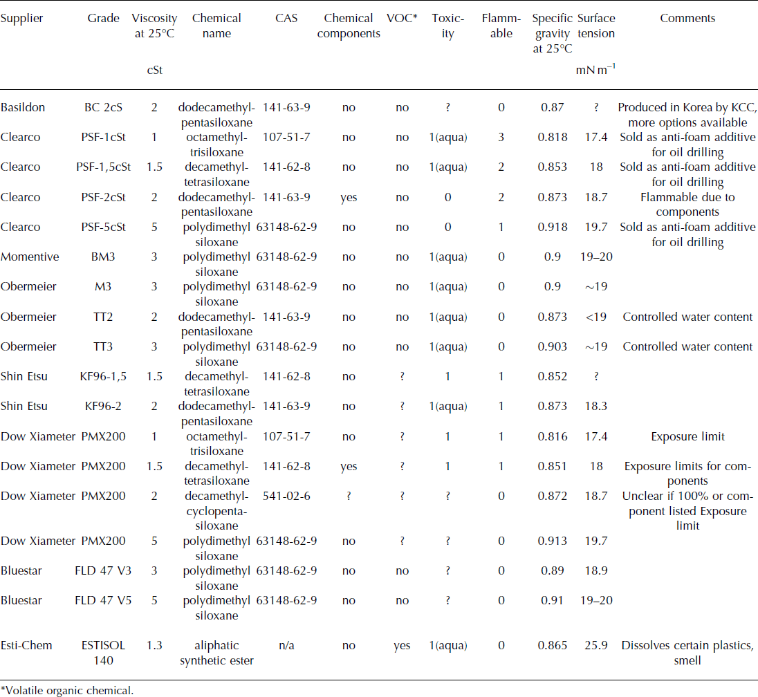
Cost indications are not listed as they vary widely depending on quantities, supplier, etc. They range from around €4.5 to €25 kg−1 for silicone oils and €3 kg−1 for ESTISOL™ 140.
Secondary Selection
ESTISOL™ 140 is considered one of the most promising drill fluids (Reference Sheldon, Popp, Hansen and SteffensenSheldon and others, 2014). It is used by Danish-, Australian- and US-led drilling projects and is therefore included in the detailed evaluation despite initial negative impressions concerning material compatibility and handling.
Figure 1 shows that the surface tension of silicone oils drops sharply with decreasing viscosity. This may have a negative effect on pump behavior and should be taken into account in the choice of pumps. It has been found that oils with viscosities <3 mm2 s−1 (<3 cSt), notably KF96-2, are more difficult to seal for properly than fluids with a slightly higher viscosity of 3 mm2 s−1 (3 cSt). While testing the effects of the fluid vapour on the spectrometer, a hollow-fibre membrane (Liquicel Micromodule debubbler, Membrana GmbH) was used to separate the gases. With a few bars of pressure differential the KF96-2 passed through the membrane to the lumen side in liquid form, but water or BM3 under the same conditions did not pass through. This demonstrates a practical consequence of the lower surface tension of the KF96-2.
The surface tension of silicone fluids drops sharply at viscosities below 5 mm2 s−1.

Also, silicone fluids with viscosities lower than 3 mm2 s −1 (3 cSt) tend to include more volatile cyclic components which can impose an exposure limit or make them flammable. However, KF96-2 from Shin-Etsu is an exception to this, and because it has also been evaluated before (Reference TalalayTalalay, 2007) it is potentially a suitable fluid and thus included in detailed testing.
Fluids with a viscosity of 5mm2 s−1 (5 cSt) are widely available and may be cheaper than 3 mm2 s−1 (3 cSt) versions, though price indications and availability vary significantly. The main downside is that at low temperatures the viscosity rises above 30 mm2 s−1 (30 cSt) at −40°C. This is considered rather high for ‘classical’ drilling operations and will have an impact on trip speed and, more importantly for the SUBGLACIOR probe, has an influence on the hydraulic losses, chip transport behaviour, etc.
This leaves the 3 mm2 s−1 (3 cSt) fluids as viable options. This group of fluids is used extensively in refrigeration systems, and grades exist that have been specifically treated to reduce the initial water content to avoid ice forming in the cooling circuits. One supplier (Obermeier) refers to this as a ‘TT’ grade. Because of the extra treatment, it was suggested that this grade might also have a lower concentration of volatile impurities from the synthesis process compared to the standard product (personal communication from Obermeier, 2014). Testing with the spectrometer system revealed that this TT grade does not cause fewer disturbances and does not justify the significantly higher cost.
As a result, the silicone oil products with most potential are: Momentive BM3, Obermeier M3 and Bluestar 47V3. When samples were received it was clear that Momentive BM3 and Obermeier M3 are exactly the same fluid, which highlights the difficulty in distinguishing between resellers and bulk producers. Both fluids were tested separately to verify that they had not undergone different treatment or chemical/physical changes due to handling or storage. These three fluids together with ESTISOL™ 140 and KF96-2 were tested and evaluated in more detail.
Detailed Evaluations of Selected Fluids
Density variations with temperature
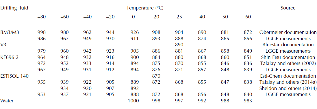
Low-temperature density measurements were made with the samples placed in an accurately temperature-controlled ethanol bath (Isotech Hydra 798) and using hydrometers (typically used to control drill fluid and densifier mixtures on drilling projects). The measurements for M3/BM3 varied from the manufacturer data and, to ensure that the results were correct, ESTISOL™ 140 and KF96-2 were also measured and compared with previously published data (Table 3; Fig. 2). In doing so we provide a direct comparison of the selected fluids, and uncertainties due to different test methods are eliminated. The difference between the measured density and manufacturer’s data can be explained by the fact that the data sheets provide a nominal value subject to some variation (personal communications from Bluestar and Obermeier, 2014). For ESTISOL™ 140 and KF96-2 the varying results are not significantly different for our application.
A listing of the varying densities (kg m–3) for the evaluated fluids. Variations are due to different measuring methods and only nominal values, subject to some change, being provided by manufacturers
Density profiles, based on test data, for the evaluated fluids with their linear equations as used for the borehole closure calculations.

Figure 2 plots the density in relation to temperature for each of the fluids and provides the linear temperature relationships obtained.
Densities accounting for compressibility
Compressibility of silicone oils is relatively high, and deep-borehole fluid-density estimates should therefore be corrected for the effects of pressure (Reference Talalay and GundestrupTalalay and Gundestrup 2002). Shin-Etsu provides detailed compressibility data for both high pressures, up to 50 MPa, and higher pressures up to 300 MPa. Data available from Bluestar are only for the higher pressures. To ensure that the compressibility is similar between the different silicone fluids, the data are compared in Figure 3 (dotted lines). This proves that compressibility for different grades can be considered the same, allowing for the detailed KF96-2 data (also shown in Fig. 3) to be used for the other silicone fluids. The compressibility for 2 mm s−1 (2 cSt) fluids is marginally higher than for 3mm2 s−1 (3 cSt) fluids, but, because no exact data are available for the latter, we used the KF96-2 data for M3, BM3 and V3.
Compressibility of 2 mm2 s−1 (2 cSt) silicone fluid at high pressures. The dotted red and green lines are plotted to compare Shin-Etsu with Bluestar data. The solid green line and its polynomial equation is for Shin-Etsu KF96-2 and used to estimate the density of silicone oil in borehole conditions.

Figure 4 shows the theoretical density profiles for the selected fluids in expected borehole conditions by using the Dome C temperature profile (personal communication from E. Lefebvre, 2014). The calculations were made using an iterative method and three iterations. No compressibility data have been found for ESTISOL™ 140, so no correction has been made. Its compressibility is likely to be somewhere between values for water and silicone oil but this has to be confirmed.
Estimated density profiles in Dome Concordia borehole conditions. The solid lines have the compressibility of the fluid taken into account. Note that no compressibility data have been found for ESTISOL™ 140. An important detail for SUBGLACIOR is that all the fluids remain less dense than water (black dotted line).

Meltwater will be pumped into the probe for analysis through a melt-tip that protrudes axially from the centre of the drill head. As previously mentioned, to avoid water rising up along the outside of the melt-tip it is important that the drill fluid remains less dense than the water. The density of the meltwater is calculated using the theoretical compressibility (Fig. 3) and assuming a temperature of 4°C. The plotted values at the top in Figure 4 show that all the selected drilling fluids, throughout, have a lower density than the meltwater.
Pressure differential and borehole closure rate
The density profiles allow the pressure differential and borehole closure rates to be estimated. Figure 5 plots the differential pressures between the overburden pressure of the ice and the hydrostatic pressure of the drill fluid column with depth. Note that these are higher than for more typical ice-core drilling projects, as the SUBGLACIOR probe will work with a fluid column right up to the surface to enable fluid circulation and chips recovery. The overburden pressure of the ice was calculated using a firn densification factor of 36m, which is typically used for Dome C (Reference TalalayTalalay and others, 2014a).
Differential pressure profiles between the fluid column pressure and the hydrostatic pressure of the surrounding ice with depth. ESTISOL™ 140 will cause an under-balanced borehole below 2300m.

The silicone fluids will create an over-pressure and ESTISOL™ 140, at lower depths, an under-pressure in the borehole. Over-pressured boreholes could in theory enlarge, and have been reported to possibly cause hydraulic fracturing and subsequent loss of fluid (Reference Lukin and VasilievLukin and Vasiliev, 2014). We consider it very unlikely that clathrate ice at depths lower than 1500 m, which is at worst subject to 1.2 MPa (12 bar) of over-pressure, would fracture. Fracturing could occur as a result of a shock or significant pressure differences in the brittle zone (personal communication from J.R. Petit, 2014), but a constant pressure differential is, in our opinion, unlikely to fracture the bubble-free practically homogeneous ice below 1000 m where the most significant over-pressure will occur. No detailed information on the deformation of an over-balanced borehole in ice, that would allow an enlargement to be calculated, has been found. Borehole logging surveys from Dye 3, Greenland, do indicate that an over-balanced borehole can expand over a period of several years (Reference Gundestrup and HansenGundestrup and Hansen, 1984). However, careful evaluation (personal communication from P. Duval, 2014) indicates that a significant enlargement of the borehole during a drilling season is unlikely and we should not simply apply the inverse of the ice-flow laws as used for borehole closure.
The closure rate for an ESTISOL™ 140 filled borehole has been estimated using Glen’s flow law (Reference Talalay and HookeTalalay and Hooke 2007; Reference TalalayTalalay and others, 2014a). Using the EPICA Dome C temperature profile the flow parameter, A, is calculated with the empirical function

where A o = 9.514 × 10¹² Mpa−3a−1, Q = 60kJ mol−1, C, Tr and k are empirical constants 4.2 K, 274.7 K and 1.25 respectively, R is the universal gas constant, 8.134J mol−1 K−1, and T is temperature (K).
Using this flow parameter the borehole closure rate was calculated using

where r o = 0.06 m, n = 3 and ΔT = 1 year are constants and ΔP(z) is the borehole pressure differential (MPa) varying with depth as shown in Figure 5. Rather than considering the borehole closure rate on the radius over the period of 1 year, the results were adjusted to represent a daily closure rate on diameter in mm d−1 and plotted in Figure 6. Clearly the borehole will be closing from 2500 m onward due to the under-pressure and the warm ice (note that flow parameter A increases with rising temperature), but the maximum rate of 0.07 mm d−1 would be acceptable as these last 700 m should be drilled and analysed in ∼4 days assuming a nominal penetration rate of 2 mm s−1. As mentioned previously, if the borehole is considered worth keeping open, this closure rate would have consequences for longer-term use of the borehole.
Borehole closure rate estimation with ESTISOL™ 140. The sharp increase below 2500 m is due to the under-pressure of the fluid and the relatively warm ice closer to bedrock (using Dome C temperature profile).

Viscosity
The viscosity of the selected fluids is evaluated for specific reasons, namely, pump power requirements for fluid circulation, probe descent speed and winching requirements for raising the probe. As mentioned before, the probe will not be raised and lowered repeatedly like a conventional drill, so in that respect the viscosity of the fluid at low temperature is less important.
Pump power in relation to viscosity, not accounting for pump efficiency, is shown in Figure 7. The relation is linear, and even at relatively high viscosities the pumping demands are acceptable because of the low flow rates.
The effect of increasing viscosity on pump power while maintaining a consistent fluid circulation flow rate for chips recovery from the borehole.

A key difference between the SUBGLACIOR probe and other deep ice-coring drills is that all the fluid will have to pass on the outside of the full length of the probe (rather than just the motor section). This will influence the descent velocity of the probe and the forces that will act on the winch when raising the probe, depending on whether fluid circulation is maintained or not. Here we evaluate the fluid viscosities in order to compare the different fluids. The exact effect on tripping speeds will be considered in the future as these are secondary criteria in the design (the operation efficiency is not reliant on the borehole tripping speeds).
Viscosity measurements were made using a calibrated Lamy Rheology RM100 rotating viscometer. It was placed over a temperature-controlled ethanol bath (Isotech Hydra 798) such that the measuring cup (Type 19) containing the sample fluid was fully submerged in the ethanol. Thermal insulation was placed around the cup to minimize the temperature gradient with the room (20°C). This set-up is preferred over placing the whole of the RM100 in a cold room as the lower temperatures affect the motor and bearings, causing erroneous measurements. The dynamic viscosity values were converted to kinematic viscosity using the appropriate densities corrected for temperature.
Initially, only M3, V3 and BM3 were tested in orderto add to previously published results for ESTISOL™ 140 and KF96-2 (Reference TalalayTalalay, 2007; Reference Sheldon, Popp, Hansen and SteffensenSheldon and others, 2014; Reference TalalayTalalay and others, 2014a). However, it was found that the measured values varied significantly from the supplier’s data and, in order to verify the test set-up, ESTISOL™ 140 and KF96-2 were also measured to allow direct comparison (Fig. 8). In the same way as for the density measurements, this allows for direct comparison of the fluids with no uncertainties about differing test set-ups, etc. Pressure has an effect on the viscosity of silicone fluids, ∼15% increase at 20 MPa, and is not taken into account in Figure 8 as the effect of pressure on viscosity of ESTISOL™ 140 is not known.
An overview of the range of measured viscosities of the evaluated fluids. The variations are mainly due to differences in test methods. Despite the variations, in general it is clear that all fluids are suitable for the project. Note that the effects of pressure (up to 15% increase at 20 MPa) have not been taken into account due to insufficient detail.

The measurements made with the RM100 were stable and repeatable and compare well with existing data at higher temperatures. However, at temperatures below -25°C the results for all the fluids are lower than the existing data despite assuring that the fluid and equipment had reached the required temperature. This has been discussed with the instrument manufacturer and fluid suppliers in order to find an explanation, but so far no conclusive reason has been found. Most likely the differences are due to the type of viscosity test (capillary, falling ball, rotating spindle) or the shear rate/gradient settings even though the fluids are considered Newtonian.
Further investigations are ongoing, and as a community it would be beneficial to find a standardized way of expressing viscosities to better compare results. The viscosity of ESTISOL™ 140 rises sharply at temperatures below −45°C, the silicone fluids less so. Our conclusion is that despite the varying results, and assuming the higher values, all the fluids are suitable, in terms of viscosity, for use in this project.
Observations from Prototype Testing
Material compatibility
None of the wide range of materials exposed to the selected silicone fluids has shown any adverse effects, which supports the widely published material compatibility data. Any silicone oil spilled on surfaces, clothing or skin wipes or washes off easily and leaves no particularly slippery surface or film. However, the evaporation rate of silicone fluids is low and any fluid on a non-wiped surface can take some time to evaporate. This is not of concern for this project but requires consideration for conventional ice-core drilling.
It is advisable to select sealing materials carefully as silicones are inert to practically all materials except themselves. Data sheets state significant swelling of pure silicone rubber (as much as 5 0% at higher temperatures) but practically no effect on fluorosilicone (fluorovinylmethyl silicone rubber/FVMQ) or fluoro-rubber (FPM/FKM/Viton) and ∼10% shrinking effect on natural rubber (NBR) (Shin-Etsu KF96 Technical Datasheet 2004.9/2011). However, throughout testing, no adverse effects have been observed on any of the polymers or sealing materials. This is in accordance with previous observations (Reference TalalayTalalay, 2007) and indicates that this consideration is only relevant at elevated temperatures.
For the SUBGLACIOR probe, the use of a gas/liquid separation membrane is being evaluated to extract the gas sample from the meltwater continuously. Silicone is one of the most gas-permeable materials and thus a suitable and widely used type of membrane. We may need to carefully test the compatibility between thin film membranes and the drill fluid, as prolonged contact could occur and any alteration or degradation of the membrane as a result should be avoided.
Questions remain about ESTISOL™ 140 due to the previously described dissolving of containers and swelling of boots, gloves, etc. Ensuring full material compatibility would mean explicit testing of the many polymer system components, which is, for now, regarded as an unnecessary task, if other affordable fluid alternatives exist.
Effects on ice chip transport
Tests are taking place in the cold room to verify the efficient ice-chips transport at varying fluid velocities and to test drill-head geometries. Throughout these tests, BM3, V3 or KF96–2 has been used extensively with excellent results. Chips have not been observed to freeze or clog together even when tightly compressed in pumps or filtration systems and they disperse easily back into the small original chips. Longterm tests for the possible influence of silicone oils on ice chips are ongoing. After >1 year of ice chips in contact with BM3 no noticeable change has been observed.
We have so far not tested the ESTISOL™ 140 in the prototype test set-ups, as it is less pleasant to work with than silicone oils. Separate tests with ice chips in ESTISOL™ 140 show no noticeable effects on the ice, confirming previous reports (Reference Sheldon, Popp, Hansen and SteffensenSheldon and others, 2014).
Solubility in solvents
Silicone fluids with higher viscosities are listed as insoluble in solvents such as glycol that may be used in an emergency to release a probe that is stuck in the borehole (Reference Gundestrup, Johnsen, Hansen, Shoji, Talalay and WilhelmsGundestrup and others, 2002). However, fluids with viscosities <5 mm2 s−1 (<5 cSt), thus including the selected drill fluids, can themselves exhibit solvent behaviour and are possibly soluble in highly polar solvents. Tests in the cold room are planned to verify this as these fluids have previously been reported as insoluble (Reference TalalayTalalay, 2007) and manufacturer’s data tend to be rather general and conflicting for the low-viscosity fluids. ESTISOL™ 140 is reported to be compatible with the solvent liquids and does not dissolve with them (Reference Sheldon, Popp, Hansen and SteffensenSheldon and others, 2014).
Water and gas absorption
Silicone oils are non-polar and immiscible with water, due to a high interfacial surface tension with it, but can absorb up to 250 ppm of water. Special grades for cooling systems exist (Obermeier GmbH, TT oils) which are supplied with a maximum water content of 50 ppm. They are intended for use in cooling systems where absorbed water will precipitate out at temperatures below 0°C and can cause blockage of the system.
We evaluated the use of this grade (see ‘Secondary selection’ above), but as the fluid will be in constant contact with ice, meltwater, etc., the absorbed water content will rise quickly to higher levels when in use, thus defeating the reason for the initial higher cost. The key difference between the industrial cooling systems and this drilling project is that we will constantly filter or melt out the ice chips generated by the drill head (up to 5% by volume), so the possible ice crystals formed from the adsorbed water content should pose no problem.
Silicone fluids are very permeable to gases, and solubility depends on the type of gas, viscosity and pressure. Typically, 0.19 cm3 of air can be dissolved per gram of silicone fluid. It is important that the dissolved gases in the circulating drill fluid do not contaminate the meltwater used for analysis, and the design of the melt-tip will minimize this. The surface of contact between the drill fluid and the sample will be small and, as the meltwater is continuously renewed by drilling deeper, any gas diffusion to the water will be minimal. Further tests to quantify this are planned as part of the sample-handling system design. No data have been found on water and gas solubility for ESTISOL™ 140.
Fluid vapour analysis with the spectrometer
Vapour from each of the fluids (at 25°C) was pumped through the prototype spectrometer (2350nm wavelength), and the results are shown in Table 4. The ring-down value (listed as ‘RD’ in the table) is an indication of the quality of fit of the spectrum and a measure of the background level disturbance on the measurement. Some drop in ring-down can be allowed and, if consistent, compensated for but it is best avoided. The tests were of a short, 30s duration to avoid contamination of the sensitive set-up with concentrated vapours.
Test results of the influence of concentrated fluid vapours on the spectrometer measurements (2350 nm laser wavelength)

KF96-2 and TT2 had little to no effect, despite possibly containing volatile components.
M3 and V3 caused a rapid drop-off, but the system also recovered quickly. Even though BM3 and M3 are in essence the same fluid, the effect on the ring-down is rather different, which will require further evaluation but is possibly due to differences in handling and packaging.
The effects of ESTISOL™ 140 were, at first, less than expected, but further evaluation of the data showed that strong additional absorption peaks had formed which indicate that the ring-down is likely to drop further. In addition, the recovery of the system was much longer, which indicates a slower but strong response to some of its components.
Cost and availability
Cost evaluation and purchasing of ESTISOL™ 140 is straightforward, with only one supplier (Esti-Chem A/S) in Denmark that can deliver sufficient quantities at relatively short notice. The current price is around e2.8 kg−1 not including shipping.
Silicone fluids are available from a large range of suppliers worldwide and prices can vary greatly. Those with a viscosity of 3 mm2 s−1 (3 cSt) are produced at lower quantities compared to >10 mm2 s−1 (>10 cSt) grades and this is reflected in availability and price. The 3 mm2 s−1 (3 cSt) grades are available at a price of less than e5kg−1 and may require delivery in batches of 8 tmonth−1, depending on supplier and production schedules. A good understanding of the market and the variety of available grades is key for effective negotiations. The higher cost can be justified by: no shipping constraints, no specific need for ventilation, less risk of component failure due to material incompatibility, and no long-term health risk for personnel, coupled with the fact that existing alternatives may, for various reasons, not be suitable.
Exploring fluid recovery from the borehole would make sense from an economic and environmental perspective, and designs are being evaluated for possible use in the future.
Final selection
All five tested fluids are suitable for the SUBGLACIOR probe, each having its advantages and disadvantages. From an initial cost point of view, ESTISOL™ 140 is the cheapest, but questions about material compatibility, together with it now being classed as an irritant, make it less attractive. In addition, its vapours have a strong disturbance on the SUBGLACIOR spectrometer spectra and it is not pleasant to work with in large quantities over a prolonged period.
KF96-2 is a very suitable liquid with no real disadvantages except for its very low surface tension, which could cause problems with, for example, sealing and running pumps. It is also the most expensive of the considered fluids.
This leaves BM3, M3 and V3, of which the first two are essentially the same fluid provided by different suppliers. They offer a good compromise on physical properties, are reported to be environmentally friendly and may be purchased for around €5 kg−1.
Two aspects to keep in mind when using silicone oil as a drill fluid are its gas absorption potential, which is much larger than with, for example, water, and its possible incompatibility with gas separation membranes. The first aspect can be minimized by an optimal design of the melt-tip and this would, to a lesser extent, be a problem with any fluid. The second aspect is now less pertinent as our initial tests indicate that the sample gases cannot be extracted efficiently enough by using this type of membrane.
The most suitable drill fluids for the SUBGLACIOR probe are V3 and M3 from Bluestar and Bayer respectively.
Conclusion
The design of the SUBGLACIOR probe is ambitious and aims to bring together new technologies to perform in situ measurements while drilling down in a single run to a depth of 3500 m in the ice sheet. The drill fluid selection is a key part in terms of costs, environmental impact and performance.
Following a detailed review of potential liquids, five were selected, four of which are silicone fluids with viscosity grades of 2 mm2 s−1 (2 cSt) and 3 mm2 s−1 (3 cSt). The fifth is an aliphatic ester, ESTISOL™ 140. They have been evaluated for general and more specific requirements such as density, viscosity, ice chips transport and their effect on laser spectrometer measurements.
ESTISOL™ 140 is the least expensive, around e3 kg−1, but is not easy to work with and can strongly affect the measurements. The low-viscosity KF96-2 is the most expensive of the silicone oils, and the small difference in viscosity does not justify the extra cost for this project.
The silicone fluids with a viscosity of 3 mm2 s−1 (3 cSt) have the right compromise in physical properties, environmental friendliness and material compatibility. When bought in bulk quantities the price can be negotiated to around e5 kg−1 or less.
Acknowledgements
This work is at the heart of four main funding projects. It has received funding from the European Research Council under the European Community’s Seventh Framework Program FP7/2007–2013 Grant Agreement No. 291062 (project ICE&LASERS). It benefits from additional funding from the French Agence Nationale de la Recherche (ANR) through the grant SIMI5-6 ANR-11-BS56-0019 (project SUBGLACIOR), and from the BNP Paribas Foundation project SUBGLACIOR. Lastly, it is part of specific equipment built in the frame of the ‘Equipement d’Excellence’ EquipEX CLIMCOR (ANR-11-EQPX-0009-CLIMCOR). Fieldwork will be supported by IPEV (France) and PNRA (Italy) at Concordia Station. We thank J.R. Petit and P. Duval for their contribution in evaluating the stability of the borehole wall when the fluid column is causing an over-pressure.



