1. Introduction
The leakage of hazardous chemicals, e.g. hydrogen and other energy gases, in the process of production, transportation, or storage is one of the main issues faced by process safety management [Reference Qi, Cao and Yntema1–Reference Xie, Liu, Kang and Zuo4]. The leakage of toxic and hazardous chemicals will cause great losses to the environment, personnel, and society. Therefore, it is very important to identify the hazard source in the atmosphere. Hence, an accurate and fast source tracing method for the release of hazardous chemicals is crucial to deal with the leakage event. On the other hand, it is also of significance to identify the emission source of contaminant gases for pollution control in the atmospheric environment.
Currently, there are two important source tracing methods. One is the source parameter estimation method based on sensor network and inversion algorithm [Reference Neumann, Asadi, Lilienthal, Bartholmai and Schiller5–Reference Ma, Tan, Zhang and Hu10]. The inverse solution model is combined with measurement data and forward dispersion model with this method. Optimization and stochastic approximation are always utilized to estimate the source term. Another source tracing method is based on mobile sensor, which is equipped on the robot [Reference Ma, Mao, Tan, Gao, Zhang and Xie11–Reference Shukla and Karki15]. Compared with the source identification method with static sensor network, mobile robot has higher ability in mobility and flexibility, and it is taking more and more attention to leakage tracing research. In this case, the concentrations are captured during the movement of the robot, and the source term is estimated with source tracing algorithm, which is guided by both gas concentrations and wind information. At present, there has been some research on leakage source tracing based on ground mobile robot [Reference Ma, Mao, Tan, Gao, Zhang and Xie11]. However, the complex terrain environment will limit the mobility of the ground robot. Hence, it is not suitable to patrol and trace emission gases for long distances and complex environments with ground robots. Compared with the ground robot, UAV (unmanned aerial vehicle) has the advantages of avoiding ground obstacles and rapid searching in a large-scale space [Reference Tisdale, Kim and Hedrick16, Reference Tomic, Schmid, Lutz, Domel, Kassecker, Mair, Grixa, Ruess, Suppa and Burschka17]. UAV can be used to sample and monitor the gas concentrations in the atmosphere to find the gas leakage source based on the tracing algorithm in a large space. At present, UAV detection methods have been preliminarily applied in different fields. However, the concentrations captured by UAV are disturbed by the airflow of rotors and the errors will be brought into the measurement, the flow velocity of the airflow below the rotor of a multi-rotor unmanned aerial vehicle and the intake of the sensor has a significant impact on the monitoring results of the sensor [Reference Li, Cao, Wang, Song, Peng, Xiu and Fu18, Reference Galle, Arellano, Bobrowski, Conde, Fischer, Gerdes, Gutmann, Hoffmann, Itikarai, Krejci, Liu, Mulina, Nowicki, Richardson, Rüdiger, Wood and Xu19]. Therefore, studying the airflow field below the rotor and optimizing the sensor position has important research value.
Published leakage tracing algorithms based on mobile sensors can be divided into two types of forms. One is bio-inspired algorithms based on the behavior of animals or microbes, such as E.coli algorithm, Zigzag, Silkworm et al.. Another category of source location with mobile sensor is based on inverse model and information-driven process [Reference Hutchinson, Oh and Chen20–Reference Branko, Alex and Ajith22], where the next movement is predicted with captured concentrations, forward model, and acquired information. All above researches were always based on ground robots and supposed that concentrations monitored by the mobile sensor are accurate. However, due to the flow field caused by the fuselage during the movement process for multi-rotor UAV, the gas sensing process will be disturbed by the flow from the surrounding gases, which will have impact on the accuracy of gas sampling and detection, and eventually affect the accuracy of source tracing. The research on how to effectively reduce the interference of outflow field on the accuracy of gas sensing with UAV is still not enough. Therefore, it is of significance to optimize the gas sampling structure of multi-rotor UAV.
Compared with the fixed-wing UAV, the cruise speed of the rotary-wing UAV is relatively low, but its manual control and fixed-point hovering abilities are relatively enhanced, making the rotary-wing UAV more fitted for stable operation in small area [Reference Niu and Wang23]. The stable structure of the centrosymmetric provides good wind resistance for rotor UAV. Although the motors increase energy consumption, multi-rotor UAVs offer advantages such as high stability, low operation difficulty, and low requirement in taking off and landing, making them useful in fields like industrial pollution inspection and fixed-point monitoring [Reference Deng, Wang, Huang, Tan and Liu24, Reference De Michele, Avanzi, Passoni, Barzaghi, Pinto, Dosso, Ghezzi, Gianatti and Vedova25]. Norsuzila et al. [Reference Ya‘acob, Zolkapli, Johari, Yusof, Sarnin and Asmadinar26] developed an environmental monitoring system based on UAV, which collected relatively accurate environmental data around the fuselage, including environmental temperature and humidity data. Rossi et al. [Reference Rossi and Brunelli27–Reference Rossi, Brunelli, Adami, Lorenzelli, Menna and Remondino29] designed a set of embedded gas monitoring platforms, which was equipped with UAV for environmental monitoring experiment and pollutant mapping. Moreover, UAV gas detection systems have also been introduced for application in complex environments, such as underground mines and chemical parks [Reference Shi, Wang, Zhang, Hu, Luo and Baim30].
However, most of the objects measured in above researches are the environmental gases with obviously high concentration, and thus the motion interference of UAV on the gas sampling could be ignored although there are still some errors in measurement. But the measurement accuracy can be significantly affected by the perturbation of airflow caused by UAVs when the objective gases in environments are with low gas concentrations. The impact of the measurement is particularly pronounced when UAVs operate in proximity to the ground, where the ground effect and the vortices generated by the interaction between the airflow and the ground exacerbate the influence of the airflow on the measurement results. Existing research and applications often address this issue by incorporating auxiliary visual sensors or employing multiple UAV arrays to enhance traceability and correct the detection results [Reference Facinelli, Larcher, Brunelli and Fontanelli31–Reference Kersnovski, Gonzalez and Morton33]. However, there is currently limited research on the impact of UAV flight, especially low altitude flight, on nearby airflow.
Because the flow field caused by multi rotors is not a simple geometric overlapped result of single rotors, there will be interaction between the wind field and fuselage during the sampling process with multi-rotor UAV. Li [Reference Li, Zhou, Lan, Hu, Zang, Liu, Luo and Zhang34, Reference Li, Zhou, Hu, Zang, Xu, Liu, Luo and Zhang35] compared and analyzed the airflow velocity models in three directions below the UAV. They found that there was mutual interference between the lateral airflows of the multi-rotor UAVs. Zheng [Reference Tan, Chen, Norton, Wang, Liu, Yang and Zheng36] found that the increase in hovering height will lead to the uniform flow field due to the attenuation of ground effect, and its turbulent flow will be gradually stable for multi-rotor UAV. They studied the downwash flow of six-rotor UAV with turbulence models, respectively, and discussed its ground effect at different hovering heights. Xue [Reference Xue, Lan, Sun, Chang and Hoffmann37] and Li et al. [Reference Li, Zhou, Sun, Wen and Chen38] simulated the fuselage turbulence of hovering twin-rotor UAV. Ryu et al. [Reference Ryu, Cho and Cho39] analyzed the turbulence effect of UAVs in crosswind environments, and Lee [Reference Lee, Oh, Choi, Lee and Park40] analyzed the fuselage flow field distribution of four-rotor UAVs in forward flight attitude. The downwash flow field generated by multi-rotor UAV is more complex than that by a single rotor, and the flow field of multi-rotors will induce and affect each other, resulting in aggregation flow. However, there are few studies on the gas sampling effect and the optimal layout of gas sensors under the condition of rotor movement.
Therefore, this research will focus on quantitative research on the parameters of the flow field in and outside the fuselage under different conditions. The gas sampling structure of UAV was optimized by simulation scenarios to improve the gas detection accuracy. Finally, the experiments will be carried out to verify the performance of the optimal sampling structure.
2. CFD simulation model of UAV
The three-dimensional scanning method was used to obtain the surface information of the blade, and the scatter cloud image was inversely processed to generate the blade model data that can be used for Computational Fluid Dynamics (CFD) simulation calculation. The complete blade model was obtained by arranging the blade near the central circular axis. Ansys Fluent 2022R1 was selected for CFD simulation. Fluent is a powerful and widely used simulation software with many advantages in the field of fluid simulation.
2.1. Titles, authors’ names and affiliation
Relevant parameters, such as the size of UAV, rotor, and calculation zone, are shown in Table 1:
The simulation parameters of CFD model.

Propeller scanning model.

The propeller scanning model used in the experiment is shown in Figure 1:
2.2. Calculation conditions
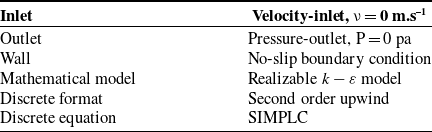
The calculation conditions and governing equations used in CFD simulation are shown in Table 2:
The calculation conditions of computational fluid dynamic model.

2.3. Governing equation
The continuity equation of incompressible fluid is mainly based on the law of mass conservation [Reference Dai, Chen and Zhou41]:
 \begin{equation}\frac{\partial \rho }{\partial t}+\frac{\partial \rho U_{i}}{\partial x_{i}}=0\end{equation}
The momentum equation in Navier-Stokes equation is mainly based on the law of momentum conservation:
 \begin{equation}\frac{\partial \rho U_{i}}{\partial t}+\frac{\partial \rho U_{i}U_{j}}{\partial x_{j}}=-\frac{\partial p}{\partial x_{i}}+\frac{\partial }{\partial x_{i}}[(\mu +\mu _{t})(\frac{\partial U_{i}}{\partial x_{j}}+\frac{\partial U_{j}}{\partial x_{i}})]\end{equation}
Where
 $\rho$
representative density;
 $t$
is the time;
 $U_{i}$
is the speed;
 $x_{i}$
and
 $x_{j}$
are coordinates;
 $p$
is the pressure; and
 $\mu$
and
 $\mu _{t}$
stand for molecular viscosity and turbulent viscosity, respectively.
The
 $\text{standard} k-\varepsilon$
model mainly uses two transfer equations to describe turbulence. One is the turbulent kinetic energy equation used to determine the turbulent energy, and the other is the turbulent dissipation equation expressing the dissipation rate of turbulent flow energy:
 \begin{align}\frac{\partial (\rho k)}{\partial t}+\frac{\partial (\rho kU_{i})}{\partial x_{i}}&=\frac{\partial }{\partial x_{j}}\left[\left(\mu _{1}+\frac{\mu _{t}}{\sigma _{k}}\right)\frac{\partial k}{\partial x_{j}}\right]+\mu _{t}\frac{\partial U_{j}}{\partial x_{i}}\left(\frac{\partial U_{i}}{\partial x_{j}}+\frac{\partial U_{j}}{\partial x_{i}}\right)-\rho \varepsilon\end{align}
 \begin{align}\frac{\partial (\rho \varepsilon )}{\partial t}+\frac{\partial (\rho \varepsilon U_{i})}{\partial x_{i}}&=\frac{\partial }{\partial x_{i}}\left[\left(\mu _{1}+\frac{\mu _{t}}{\sigma _{k}}\right)\frac{\partial \varepsilon }{\partial x_{j}}\right]+C_{1\varepsilon }\mu _{t}\frac{\partial U_{j}}{\partial x_{i}}\left(\frac{\partial U_{i}}{\partial x_{j}}+\frac{\partial U_{j}}{\partial x_{i}}\right)-C_{2\varepsilon }\rho \frac{\varepsilon ^{2}}{k}\end{align}
Where
 $k$
represents turbulent kinetic energy;
 $\varepsilon$
represents the dissipation rate of turbulent kinetic energy;
 $\mu _{1}$
is the laminar eddy viscosity coefficient; and
 $\sigma _{k}$
,
 $C_{1\varepsilon }$
, and
 $C_{2\varepsilon }$
are the model constants.
 $\text{Realizable} k-\varepsilon$
model introduces a more reasonable turbulent viscosity formula and uses a new energy dissipation rate transfer equation, which is derived from an accurate eddy current pulsation transfer equation:
 \begin{align}\frac{\partial (\rho k)}{\partial t}+\frac{\partial (\rho kU_{i})}{\partial x_{i}}&=\frac{\partial }{\partial x_{j}}\left[\left(\mu _{1}+\frac{\mu _{t}}{\sigma _{k}}\right)\frac{\partial k}{\partial x_{j}}\right]+P_{k}+P_{b}-\rho \varepsilon -Y_{M}+S_{k}\end{align}
 \begin{align}\frac{\partial (\rho \varepsilon )}{\partial t}+\frac{\partial (\rho \varepsilon U_{i})}{\partial x_{i}}&=\frac{\partial }{\partial x_{i}}\left[\left(\mu _{1}+\frac{\mu _{t}}{\sigma _{k}}\right)\frac{\partial \varepsilon }{\partial x_{j}}\right]+\rho C_{1\varepsilon }S_{\varepsilon }-C_{2\varepsilon }\rho \frac{\varepsilon ^{2}}{k+\sqrt{\nu \varepsilon }}+C_{1\varepsilon }\frac{\varepsilon }{k}C_{3\varepsilon }P_{b}+S_{\varepsilon }\end{align}
Where
 $P_{k}$
represents the turbulent kinetic energy generated by the velocity gradient;
 $P_{b}$
represents turbulent kinetic energy generated by buoyancy;
 $Y_{M}$
is the fluctuation due to the diffusion;
 $S_{k}$
and
 $S_{\varepsilon }$
are source term parameters; and
 $C_{3\varepsilon }$
is a model constant.
2.4. Grid independence
At a speed of 5000 rpm, the wind speed at 0.05 m below the UAV is used as the comparative parameter. The simulation results at different grid division scales are shown in Figure 2. From the figure, it can be observed that as the grid size decreases, the velocity variation at the observation points becomes more pronounced. The results differ by over 30% between the grid sizes of 30 mm and 40 mm. However, when the grid size is smaller than 25 mm, the velocity at the observation points remains virtually unchanged, indicating that the influence of grid size on CFD results becomes minimal when the grid size is less than 25 mm. Therefore, the best grid size was selected as 25 mm in this case.
The results of grid independence varication.

3. Simulation results
3.1. Effects of different assembly structures
The common bracket of a four-rotor UAV is located below the rotor, which can cause the bracket structure to rotate the rotor downwards, making the changes in airflow more complex. On the other hand, the sensor will be directly affected by the rotor airflow with such structure, whether the it is installed below or above the bracket, causing deviations in the detection results. In order to reduce the error caused by the position of the bracket and rotor, a UAV structure with the bracket above the rotor was tested, and the airflow fields of the two structures at 5000 rpm was compared, as shown in Figure 3.
The flow field of common four-rotor unmanned aerial vehicle at 5000 rpm.

Under common rotor structure, the support structure modifies the pressure and velocity distribution of the airflow beneath the rotor, as depicted in Figure 3a. This modification results in a higher airflow velocity below the rotor compared to configurations with an inverted rotor (Figure 3b). The increased airflow velocity shortens the contact time between the target gas and the sensor, which directly affects the accuracy of gas detection in environments with low concentrations.
For the form of reverse assembling the rotor as shown in Figure 3c, the fuselage originally installed below was moved above the rotor to avoid the influence of the fuselage on the airflow as much as possible to obtain a relatively stable surrounding flow field for gas sampling.
3.2. Flow field effects at different speeds
With the structure of reverse assembly, the flow fields of the UAV at the speed of 3000 rpm, 4000 rpm, and 5000 rpm under the condition of no wind were simulated, as shown in Figure 4.
The velocity distribution of ZY section with different speeds.

By comparing the gas velocity trace diagrams at different rotational speeds, it is evident that higher rotational speeds result in increased airflow velocity beneath the rotor. This leads to a more pronounced dispersion of the airflow and a more noticeable vortex near the ground, with a stronger ground effect. In this case, the flow field does not generate many vortices due to the drainage and interference of the fuselage at the upper inlet point, and thus the velocity distribution is relatively stable. The flow velocity under the UAV increases while the aggregation effect between the downwash flows decreases with an increase in rotating speed.
3.3. Effects of different atmospheric wind fields
The scenarios of UAV with the rotor speed of 5000 rpm under an external wind field were simulated. The wind speed was set as 0.5 m.s–1 and 2.0 m.s–1, respectively. In this case, the wind direction is in the negative direction along Z-axis. In order to clearly demonstrate the impact of transverse wind speed on the whole flow field, the velocity trajectory on the ZY plane was intercepted, as shown in Figure 5.
Velocity of different wind speed ZY sections.

It is observed that the characteristics of velocity distribution in the face of crosswind are as follows: when the wind speed is small, the airflow near the surface suppresses the wind to form a large vortex cluster; When the wind speed increases, the impact of wind speed on the near ground airflow is much greater than that of the rotor, and at this time, there are no more vortices near the ground. On the leeward side, the flow field presents different variations. When the wind speed is low, the velocity trajectories on the leeward side of the UAV are distorted greatly, and vortices are formed on the leeward side (Figure 5a). However, the trajectories on the leeward become smooth and the gas flow is relatively stable under condition with higher wind speed (Figure 5b).
4. Optimization of the sensors position
4.1. Relationship between concentration and velocity
In order to demonstrate the concentration variations in the atmosphere near the UAV, ammonia with the mass fraction of 10% was added into the calculation domain. The concentration distribution of ammonia in space is shown in Figure 6a compared with the velocity distribution in Figure 6b.
Ammonia distribution in the calculation domain.

It is noted from Figure 6 that the area with low concentration of ammonia is basically consistent with the high flow velocity distribution of gas flow. Hence, it can be concluded that the detected gas concentration is inversely proportional to the airflow velocity. Due to the inherent variability in the process of determining gas types and concentrations, the overall representativeness of the gas flow field characteristics is limited. Moreover, from the perspective of gas sensor operation principles, the environmental gas concentration alone does not accurately reflect the accuracy of sensor measurements. Gas velocity, on the other hand, not only provides a substantial indication of gas concentration but also directly influences sensor accuracy. Therefore, in subsequent sensor installation procedures, gas velocity is utilized as a key analytical parameter.
4.2. Velocity distribution above the UAV
In order to analyze the stability of the airflow in the UAV’s external flow field and find a suitable installation position for the gas sensor, the velocity distributions at different heights of the flow field above the UAV at 5000 rpm were quantitatively compared. In CFD models, the Y-axis is vertical to the ground, while the X-axis and Z-axis are parallel to the ground.
The sampling interval is established along the vertical direction at 0.01 m, 0.05 m, 0.1 m, 0.2 m, and 0.5 m above the UAV. Then, the velocity distribution on the centerline parallel to the Z-axis of the model at the corresponding height is shown in Figure 7.
Velocity distribution at different altitudes above a 5000 rpm unmanned aerial vehicle.

At the height of 0.5 m, the airflow is hardly affected by the UAV. However, the total length of UAV fuselage in this case is 0.3 m, thus the installation height of 0.5 m may have great impact on the attitude of UAV during the flight. Therefore, this position is only set as the reference and is not considered to be actual installation.
It is noted that the variation of airflow fluctuation gradually slows down with an increase in installation height. At the height of 0.01m, the vortex effect could be observed at the center of four rotors, which is the gas inlet. However, the effect of vortex can be ignored at the height of 0.2 m. Therefore, the sampling position at the height of 0.2 m above UAV can be considered as a potential good position to install the gas sensor.
When the external wind field exerts on the flow field generated by the rotors, overall space flux changes greatly. The same slice at the height of 0.2 m above the UAV was selected under the conditions with wind velocities of 0.5 m.s–1 and 1.0 m.s–1. The velocity distributions at different wind speeds were compared in Figure 8.
Comparison of velocity distribution at 0.2 m above unmanned aerial vehicle.

In the cases with the interference of wind fields under different wind speeds, the variation of velocity distribution at the height of 0.2 m demonstrates a relatively stable state and has a relatively similar law for the cases with different wind speeds. Therefore, it can be inferred that the flow field at the height of 0.2 m is influenced slightly by both rotor and external wind. Hence, the position at the height of 0.2 m above the UAV can be viewed as a potential good installation for gas sensor.
4.3. Gas velocity distribution below UAV
The slices with the sampling interval along the direction of axis Y at −0.75 m, −1.0 m, −1.25 m, −1.33 m, and −1.4 m below the UAV were selected. The velocities along the axis Z were drawn for different slices, as shown in Figure 9.
Velocity distribution at different altitudes below the 5000 rpm unmanned aerial vehicle.

It is obvious that it is difficult to find a completely stable area under the UAV. Therefore, only a relatively stable range of airflow can be determined through quantitative comparison of velocity distributions at different heights.
With an increase in height below UAV, the variations of velocity at different heights slow down first and then increase. The reason may be that the downwash airflow under the UAV rotor gradually weakens with the distance far away from the fuselage below the UAV, and the variation of velocity gradually becomes flat. As the height further decreases, the downwash airflow spreads along the ground to the surrounding area, expanding the overall impact range. Thus, the velocity tends to be an unstable state once more.
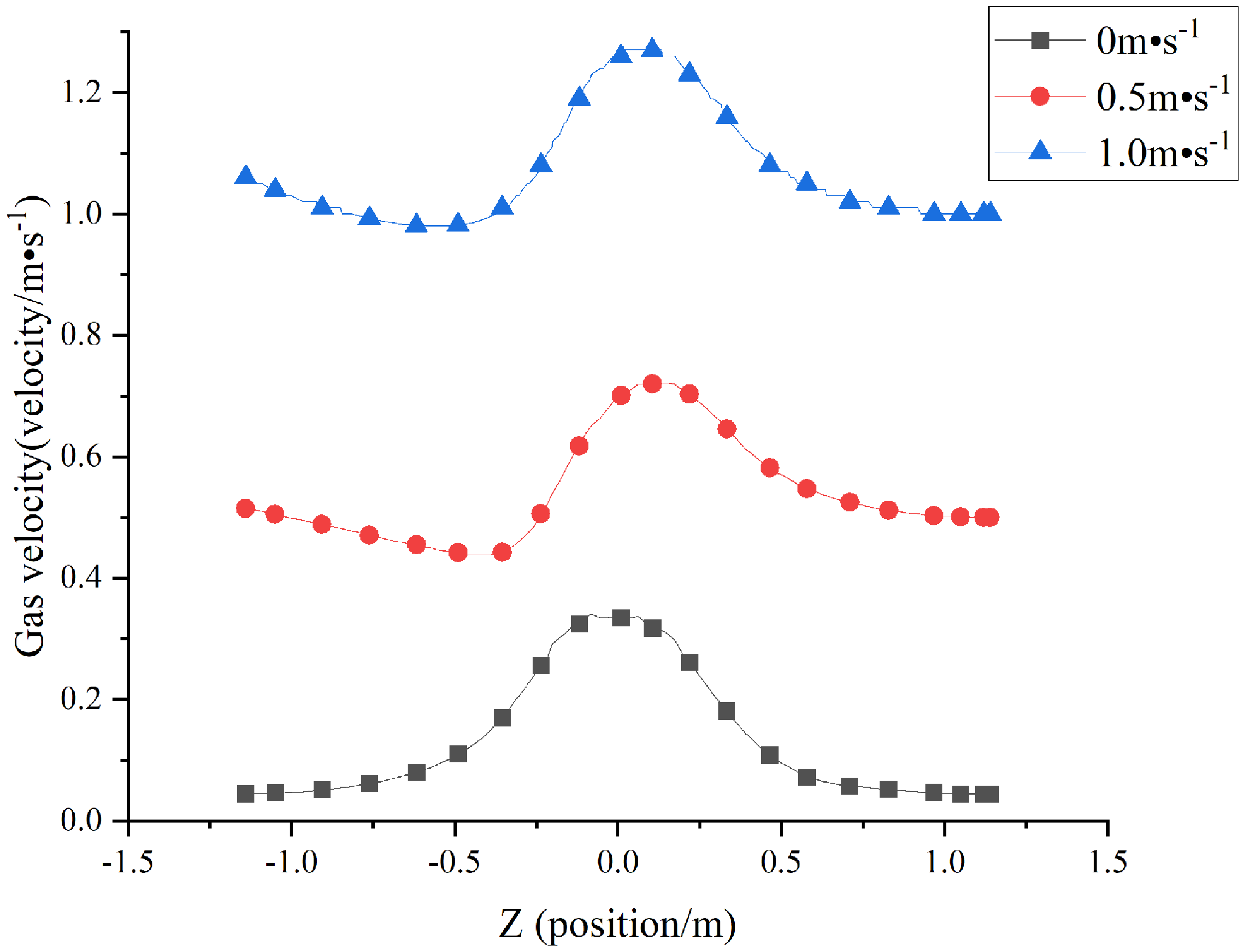
When there is a transverse wind along the reverse Z-axis in the environment, the flow field in overall space changes greatly. The flow fields are also different with different wind speeds. The results of the velocity at the height from −0.6 to −1 m along the Z-axis, with the wind speed of 0.5 m.s–1, are shown in Figure 10.
Velocity distribution at different heights under unmanned aerial vehicle with wind speed of 0.5 m.s−1.

In the case of scenarios with the interference from the wind field in the environment, the velocity distribution below the UAV changes more sharply than that in the cases without external wind fields. The transverse wind makes the downwash flow field of UAV deviate along the wind direction. Therefore, the effect of the external wind on the area right below the UAV is weakened.
By comprehensively comparing the results of velocity distribution at −1.0 m, −0.8 m, and −0.6 m, it is noted that the variation of velocity distribution at –1.0 m is relatively stable. Therefore, the gas detection can be carried out at this position with less interference from vortex clusters near the ground. In order to detect the gas below the UAV accurately, the installation position of the gas sensor should be set within −1.0 m to −1.33 m by considering the conditions with both windy and windless environments.
4.4. Velocity distribution at different rotor speeds
The velocities at the position of y = 0.2 m (above the UAV) and y = –1.15 m (below the UAV) with the rotor speeds of 3000, 4000, and 5000 rpm were captured. The results along Z-axis is shown in Figure 11.
Velocity distribution above and below the model at different speeds.

The results showed that the variation law of flow field velocity at 0.2 m above the UAV is more stable than that at –1.15m. with different rotor speeds. Therefore, it can be considered that the samples will be impacted less by the rotor flow field when the gas sensor is installed at 0.2 m above the UAV discussed in this research.
5. Verification with the experiments
Three MQ-2 gas sensors were installed at three positions including 0.2 m above the rotor, 1.15 m below the model, and 3 m far from the end of the rotor model (reference point). The concentrations of the gases were measured by MQ-2 sensor, whose response was in the form of voltage. The higher the voltage, the greater the concentration. The automatic fogger filled with the liquid ethanol was used to simulate the gas leakage release. The experimental environment and its schematic diagram are shown in Figure 12.
Experimental environment.

First, the rotor was closed. The concentrations of the emission gases near the rotor were measured. After three sensors at different positions on the rotor reached stable, the fogger was started at 5 s and then stopped at 30 s. The responses of the sensors in one minute were recorded. The process was repeated three times.
Afterwards, above process was repeated under the condition of opening the rotor with the speed of 5000 rpm. The rotor was started at 30 s. Then, the propeller and fogger were both turned off at 40 s. The responses of three sensors within one minute were observed, as shown in Figure 13.
The response values of the sensor at different positions.

Due to the heavy density of the ethanol, it is easier to accumulate near the ground. Therefore, the sensor under the rotor model detected the ethanol first, and the response values of the sensor at the lowest position increased faster than that of above sensors. Moreover, the peak value measured by the sensor at lowered position was higher than that by the sensor above the rotor, and thus the response curve decreased more slowly due to the accumulation of near the ground after the fogger was closed.
After the rotor started to rotate, the response signals collected by the gas sensor decreased, indicating that the rotor rotation increased the gas diffusion and diluted the gas concentration. After the rotor was turned on, the ethanol concentration detected by the sensors above and below the UAV decreased sharply. However, the response value of the sensor at 0.2 m above the rotor model decreased by 27% (from 78 mV to 57 mV ) while the response value at 1.15 m below the model decreased by nearly 50%(from 91 mV to 46 mV) after the rotor startup. Hence, the degree of reduction for the sensor at 0.2 m above the model was significantly less than that for the sensor at 1.15 m below the model. After the fogger and propeller both terminated, the responses at 0.2 m above the model decreased continuously, but the responses at 1.15 m below the model increased first and then dropped down. It was caused by the existence of the downwash flow field of the model, due to the low-pressure area below the model during the running of the propeller. Therefore, the temporary pressure difference between the center and the surrounding area after stopping the rotation will help the ethanol gas to reflux briefly. This phenomenon causes the ethanol concentration collected by the gas sensor at that location to rise instead of decrease in a short period of time. Hence, the results showed that the variation law of concertation at 0.2 m above the model was closer to that when the rotor was at rest. Therefore, the position at 0.2 m above the model is deemed as a better installation position than that at 1.15 m below the model.
In order to find better detection points above the model, the responses at 0.1 m above the model were compared with those at 0.2 m. The same operation process as above was repeated. The results are shown in Figure 14, where the rotor started at 30 s with the speed of 5000 rpm, and then shut down the system at 40 s.
The response values of the sensor at 0.2 m and 0.1 m above.

When the model was motionless, the variation law of responses measured at 0.2 m above the model was nearly the same as that at 0.1 m above the model. The only difference lay in that the response peak measured by the sensor at 0.1 m above the model is slightly higher than that measured at 0.2 m above the model because of the diffusion of the ethanol in vertical direction from the ground.
Since two measuring points were located above the model, the variation laws of the response values measured by two sensors were roughly the same after the model started to rotate. However, the concentrations detected by the sensor at 0.1 m above the model were lower than that at 0.2 m after the rotor rotated. Hence, the rotor movement has less impact on the position at 0.2 m above the model, and it is a fitted position to install the gas sensor for the rotor UAV.
6. Conclusion
In this research, CFD simulation method based on ANSYS fluent was used to study the gas flow field of four-rotor UAV under different conditions to find a potential good insulation position for gas sensor. The results showed that the structure of common UAV will lead to the instability of the downwash flow field during its movement, which has impact on the gas sampling. Moreover, the atmospheric conditions and the speed of UAV also affect the sampling process.
Based on the simulation results, the form of reverse assembling the rotor was better than common rotor structure. The influence of the rotor on the flow field around the rotor structure could be reduced significantly with reverse assembling structure, which provides a feasible area for gas sampling. The quantitative results under different atmospheric conditions and rotor speeds showed that the variations of the flow velocity above the model of UAV is relatively stable than that below the model. Moreover, the flow velocity above the UAV is relatively low, thus it is more suitable for gas sampling.
The experimental results of gas sampling based on reverse assembled rotor showed that the collected data at 0.2 m above the UAV model performed better than that at other installation positions, which can meet the sampling requirements.
Accordingly, though there are still some problems such as for larger UAV devices and more complex atmospheric conditions, the gas sampling optimization discussed in this research can provide good data support for the gas sensing structure with UAV, which is helpful to build an accurate and effect source tracing algorithm based on UAV. It can be applied in the fields of monitoring and identifying the leakage of hazardous gases as well as the emission of contaminant gases in the atmosphere.
Author contribution
DM is the supervisor and designed the research method. SG was in charge of the whole analyses and wrote the initial manuscript; and YZ assisted with simulation analyses. All authors read and approved the final manuscript.
Financial support
Financial support was provided by the Key Research and Development Program of Shaanxi Province (2023-YBSF-266) and China Postdoctoral Science Foundation (2021T140544).
Competing interests
The authors declare no competing interests exist.
Ethical approval
None.