


1 Introduction
When a moving planar shock wave impinges a straight compressive wedge, the so-called pseudo-steady shock reflection will occur. Depending on the strength of incident shock wave and wedge angle, a regular reflection (RR) or a Mach reflection (MR) will take place (Hornung Reference Hornung1986). The MR configuration generally consists of three shocks (an incident shock, a reflected shock and a Mach stem) and one slipstream which all intersect at one point (the triple point). In shock dynamics, the Mach stem is usually assumed to be straight and perpendicular to a solid wall (Ben-Dor Reference Ben-Dor2007) although a curved Mach stem has been observed by many experiments and numerical simulations (see Ando Reference Ando1981; Lee & Glass Reference Lee and Glass1982; Glaz et al. Reference Glaz, Colella, Collns and Ferguson1988; Semenov, Berezkina & Krassovskaya Reference Semenov, Berezkina and Krassovskaya2012). The shape of the Mach stem plays an important role in solving Mach stem height and subsequently influences the range of the subsonic region behind the Mach stem. Therefore, the investigation of the deformation of the Mach stem not only completes the theory of shock reflection, but also reveals the fundamental mechanisms in some physical phenomena, including non-uniform reservoir flow of a shock tunnel (Hornung Reference Hornung2000), detonation re-initiation (Radulescu & Maxwell Reference Radulescu and Maxwell2011; Bhattacharjee et al. Reference Bhattacharjee, Lau-Chapdelaine, Maines, Maley and Radulescu2013) and cell multiplication (Mach & Radulescu Reference Mach and Radulescu2011).
Schematic configurations of shock wave reflections involving Mach stem deformation: (a) steady shock reflection with a concave Mach stem; (b) pseudo-steady shock reflection with a convex Mach stem; (c) unsteady shock interaction in cellular detonation with a convex Mach stem. Symbols
 $i,r,s$
and
 $m$
refer to the incident shock wave, reflected shock wave, slipstream and Mach stem, respectively.

The deformation of the Mach stem can be concave or convex to the undisturbed flow. Most of previous investigations on the concave deformation of the Mach stem dealt with steady shock wave reflections, as sketched in figure 1(a). In such reflections, the concave Mach stem is induced by the disturbance of the rarefaction waves from the rear end of the wedge (Li & Ben-Dor Reference Li and Ben-Dor1997; Bai & Wu Reference Bai and Wu2017). Most convex (or protruding) Mach stems were found in shock diffraction (Ando Reference Ando1981) and cellular detonation (Sharpe Reference Sharpe2001), as respectively shown in figure 1(b,c). The inward curl of the slipstream generates a jet along the wall or symmetry axis, and produces compressional disturbances to the Mach stem. In irregular cellular detonations, the curling slipstream stirs the flow behind the Mach stem and enhances the mixing and reaction rates of unburned pockets (Mazaheri, Mahmoudi, & Radulescu Reference Mazaheri, Mahmoudi and Radulescu2012). The deformed Mach stem transits from a smoothly curving structure to a triple-shock structure when the deformation becomes significant. This process was found to play an important role in the formation of new cells in cellular detonations (Mach & Radulescu Reference Mach and Radulescu2011). However, there were only very few theoretical investigations on the mechanism of the deformation of the Mach stem. Assuming a frozen and inviscid flow, Li & Ben-Dor (Reference Li and Ben-Dor1999) provided a criterion for the protruding Mach stem, and found that if the wall jet is quick enough to catch up with the Mach stem, the Mach stem will become convexly curved. They also predicted the inclination angle of the Mach stem by shock dynamics theory. Henderson et al. (Reference Henderson, Vasilev, Ben-Dor and Elperin2003) studied the details of the wall jet in the MR. A transition criterion between jetting and non-jetting was proposed under a frozen, inviscid and self-similar flow assumption. The wall jet was found to be unstable because of the existence of an inner sonic throat.
These investigations gave a preliminary recognition to the formation of a convex Mach stem. However, how to correctly predict the jet disturbance and Mach stem deformation remains unclear. We notice that previous theoretical models can give a good agreement with experimental data only in mild deformation cases, but will fail for cases with a large deformation of the Mach stem. The remarkable deformation of the Mach stem is usually found in strong shock reflection, and the high-temperature gas effects were supposed to play an important role for the large deformation of the Mach stem (Glaz et al. Reference Glaz, Colella, Collns and Ferguson1988). Therefore, the mechanism of high-temperature gas effects on the Mach stem deformation remains to be discovered. This motivates the present study.
2 Physical models and methods
The flow system in this study is described by the two-dimensional Euler equations containing finite-rate chemical reaction and vibrational relaxation source terms as
 $$\begin{eqnarray}\frac{\unicode[STIX]{x2202}}{\unicode[STIX]{x2202}t}\left(\begin{array}{@{}c@{}}\unicode[STIX]{x1D70C}_{i}\\ \unicode[STIX]{x1D70C}u\\ \unicode[STIX]{x1D70C}v\\ \unicode[STIX]{x1D70C}e\\ \unicode[STIX]{x1D70C}e_{v}\\ \end{array}\right)+\frac{\unicode[STIX]{x2202}}{\unicode[STIX]{x2202}x}\left(\begin{array}{@{}c@{}}\unicode[STIX]{x1D70C}_{i}u\\ \unicode[STIX]{x1D70C}u^{2}+p\\ \unicode[STIX]{x1D70C}uv\\ \unicode[STIX]{x1D70C}ue+up\\ \unicode[STIX]{x1D70C}ue_{v}\\ \end{array}\right)+\frac{\unicode[STIX]{x2202}}{\unicode[STIX]{x2202}y}\left(\begin{array}{@{}c@{}}\unicode[STIX]{x1D70C}_{i}v\\ \unicode[STIX]{x1D70C}uv\\ \unicode[STIX]{x1D70C}v^{2}+p\\ \unicode[STIX]{x1D70C}ve+vp\\ \unicode[STIX]{x1D70C}ve_{v}\\ \end{array}\right)=\left(\begin{array}{@{}c@{}}\dot{\unicode[STIX]{x1D714}_{i}}\\ 0\\ 0\\ 0\\ S_{v}\\ \end{array}\right),\end{eqnarray}$$
where
 $\unicode[STIX]{x1D70C}_{i}$
is the density of chemical species
 $i$
,
 $\unicode[STIX]{x1D70C}=\sum \unicode[STIX]{x1D70C}_{i}$
is the density of the gas mixture;
 $u$
and
 $v$
are the velocities in the
 $x$
- and
 $y$
-direction, respectively;
 $e$
is total energy per unit mass,
 $e_{v}$
is vibrational energy per unit mass;
 $\dot{\unicode[STIX]{x1D714}_{i}}$
and
 $S_{v}$
are the mass production rate of species
 $i$
and average vibrational energy relaxation rate, respectively;
 $p$
is pressure, which is given by
 $$\begin{eqnarray}p=R_{u}T\mathop{\sum }_{i=1}^{N_{s}}\frac{\unicode[STIX]{x1D70C}_{i}}{W_{i}},\end{eqnarray}$$
where
 $N_{s}$
is the total number of involved chemical species,
 $W_{i}$
is the molecular weight of species
 $i$
,
 $R_{u}$
is the universal gas constant and
 $T$
is the translational temperature.
The high-temperature non-equilibrium of standard air is simulated using the two-temperature vibrational relaxation model (Park Reference Park1987) and the five-species (
 $\text{N}_{2}$
,
 $\text{O}_{2}$
, N, O, NO) chemical kinetics model (Park Reference Park1993). The equilibrium thermodynamic properties of the gas components are calculated by the curve fits of Gupta et al. (Reference Gupta, Yos, Thomopson and Lee1989). To show high-temperature gas effects, three gas models, namely frozen (
 $\dot{\unicode[STIX]{x1D714}_{i}}=0,S_{v}=0$
), thermal non-equilibrium (
 $\dot{\unicode[STIX]{x1D714}_{i}}=0,S_{v}\neq 0$
) and thermochemical non-equilibrium (
 $\dot{\unicode[STIX]{x1D714}_{i}}\neq 0,S_{v}\neq 0$
), are implemented.
The conservation equations are solved with an explicit finite volume method based on unstructured quadrilateral grids (Sun & Takayama Reference Sun and Takayama1999). The convection fluxes are integrated by the MUSCL (monotonic upwind scheme for conservation laws)-Hancock scheme (Toro Reference Toro2009), and the thermochemical source terms are integrated by VODE (Byrne & Dean Reference Byrne and Dean1993) – an open-source solver for ordinary differential equations. The two are coupled by the fractional step method (Mazaheri et al. Reference Mazaheri, Mahmoudi and Radulescu2012). An adaptive mesh refinement (AMR) technique is used to deploy dense grids in flow regions with large density and velocity gradients (Sun & Takayama Reference Sun and Takayama1999), thereby resolving shock waves as well as other small-scale flow structures in an efficient way. The reader is referred to Li & Luo (Reference Li and Luo2014) for a detailed description of the physical model and numerical method.
Comparison between experimental data (a, interferogram; c, wall density distribution (Glaz et al.
Reference Glaz, Colella, Glass and Deschambault1985)) and inviscid numerical result (b,c). Here
 $l$
is the horizontal distant from the Mach stem root to the compressional corner. The incident shock Mach number is 8.86, and the wedge angle is
 $20^{\circ }$
.

Although the accuracy and reliability of the numerical method have been confirmed in previous studies, it has not been previously validated against actual physical results. Therefore, a relevant comparison is presented to demonstrate that the assumptions that underpin the numerical solver are good approximations for the physical system. Figure 2 shows a comparison of flow patterns (interferograms) and wall density distribution between experiment by (Glaz et al.
Reference Glaz, Colella, Glass and Deschambault1985) and numerical simulation by the current method for a double Mach reflection over a wedge with a wedge angle of
 $20^{\circ }$
and an incident shock Mach number of 8.86. It can be seen that the current numerical method reasonably captures the Mach stem deformation and the flow behind the Mach stem, which validates the adequacy of the present numerical method. It should be noted that this validation only shows that the inviscid solver captures the global structure of the interaction well, which is appropriate for this paper as we are only concerned with global features.
The computational domain: (a) background grids and boundary conditions; (b) the general flow and view zone.

The computational zone with initial grids is shown in figure 3(a). The wedge surface and the leading level surface are set as adiabatic non-catalytic slip walls, other boundaries are non-reflecting openings. For AMR, based on an examination of mesh convergence (see the Appendix), a maximum refinement level of 6 is employed for all cases and the minimum grid size can reach
 $17~\unicode[STIX]{x03BC}\text{m}$
, i.e.
 $1/4500$
of the wedge length. The initial temperature and pressure of the undisturbed flow are 293 K and 0.05 atm, respectively. The incident shock Mach number
 $M_{s}$
is set from 6 to 9 and the wedge angle
 $\unicode[STIX]{x1D703}_{w}$
is from
 $25^{\circ }$
to
 $45^{\circ }$
. A typical flow is shown in figure 3(b), in which a view zone is marked for presenting flow details for the rest of the paper.
3 Flow structures and characteristics
The MR can be further classified into single MR (SMR), transitional MR (TMR) and double MR (DMR). By varying gas models, two typical deformations of the Mach stem are observed in the DMR as representatively shown in figure 4. Figure 4(a,c) shows one case which uses the frozen gas model, and figure 4(b,d) another which uses the thermochemical non-equilibrium model. The wedge angle is
 $35^{\circ }$
and the incident shock Mach number is 9 in these two cases.
Two typical flow patterns with a deformation of the Mach stem in DMR shown by density gradient contours (a,b) and streamlines (c,d). (a,c) DM–WR in frozen flow and (b,d) TM–WR in thermochemical non-equilibrium flow. The wedge angle is
 $35^{\circ }$
and the incident shock Mach number is 9. K, stagnation point; G, root of Mach stem; T,
 $\text{T}^{\prime }$
and
 $\text{T}^{\prime }$
, triple points; T
 $\text{T}^{\prime }$
, first reflected shock;
 $\text{T}^{\prime }$
D, secondary reflected shock. Blue streamlines represent the flows through the Mach stem, and red and yellow streamlines represent those through the incident shock.

The wave structures are similar for the cases. The primary Mach reflection consists of an incident shock wave (TI), a reflected shock wave (
 $\text{T}\text{T}^{\prime }$
), a Mach stem (TG) and a slipstream (TD), with T being the primary triple point. For DMR, there is a secondary Mach reflection in which
 $\text{T}\text{T}^{\prime }$
reflects again to form a new (secondary) reflected shock wave (
 $\text{T}^{\prime }\text{D}$
) and a new slipstream (
 $\text{T}^{\prime }\text{E}$
). These shock waves and slipstreams divide the flow into six regions which are labelled (0)–(5) respectively in figures 4(a) and 4(b). Note that
 $\text{T}^{\prime }\text{E}$
is too weak to be illustrated by density contours.
For the frozen flow (figure 4 a), shock layers are found to be sharp and smooth, and many Kelvin–Helmholtz (K–H) vortices occur along the slipstream TD. For the non-equilibrium flow (figure 4 b), we observed that the Mach stem is much shorter and the shock layers become thick and coarse because the thermochemical relaxation layer clings to the shock front. The K–H vortices along TD are not as evident as the former case because the density difference across TD declines in the non-equilibrium flow and hence suppresses the growth of the mixing zone (Rikanati, Alon & Shvarts Reference Rikanati, Alon and Shvarts2003).
In both cases, a jet is generated around the intersection of slipstream and wedge surface. The jet shoots forward along the surface and finally rolls up to form a large vortex. Disturbed by the vortex, the lower part of the Mach stem protrudes as an arc, with the root keeping perpendicular to the wall. The major difference between the two cases lies in the structure of the deformed Mach stem. Figure 4(a) presents a whole piece of smoothly curved Mach stem, while in figure 4(b) a new triple point T
 $^{\prime \prime }$
is formed in the middle. Following the definition of Semenov et al. (Reference Semenov, Berezkina and Krassovskaya2012), the former reflection is referred to as DM–WR (double Mach–White reflection) and the latter as TM–WR (triple Mach–White reflection).
The flow structure is self-similar over time for pseudo-steady shock reflection. Therefore, a moving coordinate system can be applied to analyse the flow characteristics (Henderson et al. Reference Henderson, Vasilev, Ben-Dor and Elperin2003) such that the relative velocities to a local point of the flow structure are expressed as
 $$\begin{eqnarray}u_{r}=u-\frac{x}{x_{s}}M_{s}a_{0},\quad v_{r}=v-\frac{y}{x_{s}}M_{s}a_{0},\end{eqnarray}$$
where
 $u_{r}$
and
 $v_{r}$
represent the relative velocities in the
 $x$
- and
 $y$
-directions, respectively:
 $(x,y)$
are ordinates of the local point in the fixed frame;
 $x_{s}$
is the horizontal distance from the leading end of the wedge (point O in figure 3
b) to the position of the incident planar shock;
 $a_{0}$
denotes the speed of sound in region (0).
Pressure and relative flow velocity along the wall in region (3). The abscissa starts from the stagnation point K where the relative velocity is zero, and is normalized by the distance from K to G (Mach stem root);
 $p_{0}$
is the pressure in region (0).

The streamlines for (
 $u_{r},v_{r}$
) are shown in figure 4(c,d). The lower part of the incoming flow (blue streamlines) passes through the Mach stem and is confined in region (3). The upper part of the incoming flow crosses over the incident shock and first reflected shock successively, and is then split into two flow branches (red and yellow streamlines) at a stagnation point K on the wall. The rightward branch (red streamlines) develops into the wall jet. As shown by the wall pressure and velocity distributions in figure 5, the propagation of the wall jet in both DM–WR and TM–WR cases can be divided into three phases. At first, the rightward flow accelerates quickly with a rapid decrease of pressure (K–A). Via this process the so-called wall jet forms. Then the wall jet enters a relatively stable phase in which the mean pressure is balanced with that in region (3) and the mean velocity decreases slightly, regardless of the small oscillations caused by the K–H instability. Finally, the wall jet rolls up into a big vortex. Along with the roll-up vortex, the wall pressure decreases and the velocity along the wall increases. The composition of streamlines in the roll-up vortex indicates that the vortex entrains nearby flow.
The flow patterns shown by entropy contours (a–c) with thermochemical non-equilibrium effect, and deformation extent of the Mach stem (d) varying with the incident shock Mach number in the frozen, thermal non-equilibrium and thermochemical non-equilibrium flows. The wedge angle is
 $35^{\circ }$
for all cases.

High-temperature gas effects have a significant influence on the wave pattern. For frozen flow, TM–WR hardly happens even under the most extreme condition, whereas for thermochemical non-equilibrium flow (which is realistic for strong shocks) a gradual transition from DM–WR to TM–WR may occur when the incident shock is strengthened, as shown in figure 6(a–c). To quantitatively evaluate the deformation of the Mach stem, a dimensionless parameter
 $f$
is defined to describe the deformation extent:
 $$\begin{eqnarray}f=\unicode[STIX]{x1D6FF}/h,\end{eqnarray}$$
where
 $\unicode[STIX]{x1D6FF}$
is the distance between the root of the actual Mach stem and that of the ideal straight one, and
 $h$
is the height of Mach stem, as illustrated in figure 6(a).
The dimensionless deformation extent
 $f$
for different gas models and incident shock Mach numbers are summarized in figure 6(d). It is clear that high-temperature gas effects always tend to intensify the deformation of the Mach stem. The introduction of vibrational relaxation (thermal non-equilibrium) causes an evident rise of
 $f$
, and the influence becomes more pronounced as the incident shock becomes stronger. Further introduction of a chemical reaction (thermochemical non-equilibrium) does not cause much difference when
 $M_{s}<6$
, but then a dramatic increase of
 $f$
takes place when
 $M_{s}$
increases from 6 to 8, indicating a massive occurrence of molecular dissociation. The contribution of the chemical reaction to
 $f$
reaches a peak around
 $M_{s}=8$
after which the effect of the chemical reaction is nearly levelled. We also notice that the occurrence of the new triple point on the Mach stem seems to be largely dependent on
 $f$
. For the present study, the transition criterion between DM–WR and TM–WR is found to be
 $f\approx 0.15$
.
4 Theoretical analysis and discussion
4.1 Theoretical model
The deformation extent of the Mach stem is an important parameter that characterizes the deformation phenomenon. Li & Ben-Dor (Reference Li and Ben-Dor1999) proposed a theoretical model to predict the deformation of the Mach stem for frozen flow, in which the velocity of the wall jet was considered as the dominant factor. In this paper, we shall revisit the problem and build a new theoretical model that involves the flux of the wall jet.
A self-similar flow is assumed, as shown in figure 7(a). We take the subsonic region bounded by the Mach stem and slipstream as the control body (figure 7 b). The control body grows over time and there are two influxes that contribute to the growth – the flow across Mach stem and wall jet. Assuming the densities of the wall jet and the inflow from the Mach stem remain constant, a conservation of volume of the control body can be established,
 $$\begin{eqnarray}\frac{\text{d}\unicode[STIX]{x1D6FA}}{\text{d}t}=h\cdot u_{m}+h_{j}\cdot u_{j},\quad \unicode[STIX]{x1D6FA}=\frac{1}{2}h^{2}\cdot (\cot \unicode[STIX]{x1D6FC}+f),\end{eqnarray}$$
where
 $\unicode[STIX]{x1D6FA}$
is the volume of the control body,
 $\unicode[STIX]{x1D6FC}$
is the angle between slipstream and wedge wall,
 $u_{m}$
is the inflow velocity from TG and with respect to the Mach stem,
 $u_{j}$
is the velocity of the wall jet with respect to point K and
 $h_{j}$
is the wall-jet thickness. The volume equation involves the approximation that the
 $s$
-shaped Mach stem is represented by a straight line TG. In this way, the deformation extent
 $f$
is introduced. With the self-similar assumption,
 $f$
and
 $\text{d}h/\text{d}t$
are supposed to be constant over time.
Schematics of the theoretical model showing (a) the self-similar flow of Mach reflection, (b) an enlarged view of the control body and (c) the pseudo-steady flow in the vicinity of and with respect to the triple point.

Rearranging the equations yields
 $$\begin{eqnarray}f=\frac{h_{j}\cdot u_{j}}{h\cdot \text{d}h/\text{d}t}+\frac{u_{m}}{\text{d}h/\text{d}t}-\cot \unicode[STIX]{x1D6FC},\quad h=\frac{\sin \unicode[STIX]{x1D712}}{\cos (\unicode[STIX]{x1D703}_{w}+\unicode[STIX]{x1D712})}\cdot x_{s},\end{eqnarray}$$
where
 $\unicode[STIX]{x1D712}$
stands for the trajectory angle of triple point T. Accordingly, volume conservation for a case where there is no wall jet or Mach stem deformation reveals
 $$\begin{eqnarray}f(u_{j}=0)=\frac{\bar{u}_{m}}{\text{d}\bar{h}/\text{d}t}-\cot \bar{\unicode[STIX]{x1D6FC}}=0,\quad \bar{h}=\frac{\sin \bar{\unicode[STIX]{x1D712}}}{\cos \left(\unicode[STIX]{x1D703}_{w}+\bar{\unicode[STIX]{x1D712}}\right)}\cdot x_{s},\end{eqnarray}$$
with ‘–’ referring to parameters in this case. We make a further simplification that
 $\unicode[STIX]{x1D6FC}$
and
 $u_{m}$
are not affected by the deformation of the Mach stem. Replacing
 $\unicode[STIX]{x1D6FC}$
and
 $u_{m}$
with
 $\bar{\unicode[STIX]{x1D6FC}}$
and
 $\bar{u}_{m}$
, and eliminating
 $\bar{u}_{m}$
, the
 $f$
equation changes to
 $$\begin{eqnarray}f=\frac{h_{j}\cdot u_{j}}{h\cdot \text{d}h/\text{d}t}+\left(\frac{\bar{h}}{h}-1\right)\cdot \cot \bar{\unicode[STIX]{x1D6FC}},\end{eqnarray}$$
which involves six unknowns:
 $f$
,
 $h_{j}$
,
 $u_{j}$
,
 $\unicode[STIX]{x1D712}$
,
 $\bar{\unicode[STIX]{x1D712}}$
,
 $\bar{\unicode[STIX]{x1D6FC}}$
.
The pseudo-steady flow at T (figure 7
c) provides extra correlations. Because of the deformation, the Mach stem segment adjacent to T is no longer perpendicular to the wall. We introduce a deflection angle,
 $\unicode[STIX]{x1D700}$
, to define the orientation of this part of the Mach stem. Given
 $\unicode[STIX]{x1D700}$
is known, the flow (including the wave angles) can be fully solved. Hence,
 $$\begin{eqnarray}\unicode[STIX]{x1D712}=\unicode[STIX]{x1D712}\left(\unicode[STIX]{x1D700}\right),\quad \unicode[STIX]{x1D6FC}=\unicode[STIX]{x1D6FC}\left(\unicode[STIX]{x1D700}\right);\quad \text{and}\quad \bar{\unicode[STIX]{x1D712}}=\unicode[STIX]{x1D712}\left(\unicode[STIX]{x1D700}=0\right),\quad \bar{\unicode[STIX]{x1D6FC}}=\unicode[STIX]{x1D6FC}\left(\unicode[STIX]{x1D700}=0\right).\end{eqnarray}$$
The wall jet is essentially one branch of the mainstream originated from
 $\text{T}\text{T}^{\prime }$
(figure 4). By considering an incompressible jet (the mainstream) impinging on a wall at an angle
 $\unicode[STIX]{x1D6FC}$
(Kundu, Cohen & Dowling Reference Kundu, Cohen and Dowling2011), the thickness of the wall jet can be modelled as
 $$\begin{eqnarray}h_{j}=g\cdot l_{TT^{\prime }}\cdot \sin \unicode[STIX]{x1D6FD}_{rs}\cdot (1-\cos \unicode[STIX]{x1D6FC}),\end{eqnarray}$$
where
 $l_{TT^{\prime }}$
denotes the distance between T and T
 $^{\prime }$
(or the kink in TMR),
 $\unicode[STIX]{x1D6FD}_{rs}$
denotes the angle between the reflected shock and the slipstream and
 $g$
is a constant coefficient ranging from 6.4 to 7.4;
 $l_{TT^{\prime }}$
uses the assumption of Law & Glass (Reference Law and Glass1970),
 $\text{d}l_{TT^{\prime }}/\text{d}t=u_{1n}/\!\sin \unicode[STIX]{x1D6FD}_{ir}$
with
 $u_{1n}$
the horizontal flow velocity behind incident shock and
 $\unicode[STIX]{x1D6FD}_{ir}$
the angle between the incident shock and the reflected shock. For the wall-jet velocity, because the flow entropy barely changes from region (2) to the jet and the pressures in regions (2) and (3) are balanced, the velocity difference across the jet boundary almost returns to that across the slipstream at
 $\text{T}$
. Therefore
 $u_{j}$
is approximated by
 $$\begin{eqnarray}u_{j}=u_{2}-u_{3},\end{eqnarray}$$
where
 $u_{2}$
and
 $u_{3}$
are the flow velocities relative to T in regions (2) and (3), respectively. In the DMR case, the secondary reflected shock
 $\text{T}^{\prime }\text{D}$
may cause entropy change along the streamlines and thereby cause
 $u_{j}$
to deviate from
 $u_{2}-u_{3}$
. Li & Ben-Dor (Reference Li and Ben-Dor1999) took this effect into consideration by calculating
 $u_{j}$
through an isentropic process from region (5) to region (3). The effect is trivial according to our examination, however.
The above modelling allows us to find
 $h_{j}$
and
 $u_{j}$
with a known triple point flow. To solve
 $f$
, one more equation is required. The first clue that comes to the mind is that, as the transition between DM–WR and TM–WR largely depends on
 $f$
, the geometry of the deformed Mach stem may follow a common pattern that applies under a wide range of conditions. In this manner, the deflection angle of the Mach stem near the primary triple point,
 $\unicode[STIX]{x1D700}$
, will be a function of
 $f$
only. By examining the numerical data of
 $\unicode[STIX]{x1D700}$
and
 $f$
under varied gas models and test conditions, we do find that the two geometrical parameters are highly correlated, as shown in figure 8;
 $\text{tan}\,\unicode[STIX]{x1D700}$
nearly equals
 $f$
when
 $f$
is small and then turns to a slow increase with
 $f$
, corresponding to a transition from DM–WR to TM–WR.
By fitting the numerical data, a logarithmic equation is deduced as follows:
 $$\begin{eqnarray}\tan \unicode[STIX]{x1D700}=\min [a\ln (b\cdot f+1),f],\quad \text{with }a=0.0116,b=176.\end{eqnarray}$$
Numerical data and fitting curve for the deflection angle of the Mach stem near the primary triple point,
 $\unicode[STIX]{x1D700}$
, varying with the deformation extent of the Mach stem,
 $f$
. The numerical data cover an incident shock Mach number from 1.5 to 9 and a wedge angle from
 $20^{\circ }$
to
 $45^{\circ }$
, and with the frozen, thermal equilibrium and thermochemical non-equilibrium gas models.

Thus far, the equations are complete and
 $f$
can be solved by iteration. We remark that the equations remain complete for high-temperature equilibrium flow because the internal energy and the chemical composition of a gas mixture at equilibrium are merely dependent on the local thermodynamic state.
Numerical and theoretical results of the deformation extent
 $f$
varying with the wedge angle. (a) Frozen flow, (b) thermal equilibrium flow. The black symbols and lines are for
 $M_{s}=6$
, and the red ones are for
 $M_{s}=9$
.

Equation (4.4) (together with (4.3)) can be rearranged as
 $$\begin{eqnarray}f=\frac{Q_{j}-\unicode[STIX]{x0394}Q_{m}}{\dot{\unicode[STIX]{x1D6FA}}_{o}}\cdot \cot \bar{\unicode[STIX]{x1D6FC}},\end{eqnarray}$$
where, as shown in figure 7(b),
 $\dot{\unicode[STIX]{x1D6FA}}_{o}=h\cdot \text{d}h/\text{d}t\cdot \cot \bar{\unicode[STIX]{x1D6FC}}$
denotes the volumetric growth rate of
 $\unicode[STIX]{x0394}\text{TKG}_{o}$
,
 $Q_{j}=u_{j}\cdot h_{j}$
denotes the volume flux of the wall jet and
 $\unicode[STIX]{x0394}Q_{m}=h\cdot \bar{u}_{m}(h/\bar{h}-1)$
is the deficit of volume flux from the Mach stem due to the offset of the Mach stem height caused by deformation.
 $Q_{j}$
is the cause of the Mach stem deformation, whereas
 $-\unicode[STIX]{x0394}Q_{m}$
is an adaptation of the wave structure that resists the deformation. The two terms cancel each other and result in a net effective flux,
 $Q_{a}=Q_{j}-\unicode[STIX]{x0394}Q_{m}$
, which generally maintains the tendency of
 $Q_{j}$
. From (4.9), we may see how the deformation extent responds to a change of the wall-jet flux, e.g.
 $Q_{j}\uparrow$
 $\Rightarrow$
 $f\uparrow$
 $\Rightarrow$
 $\unicode[STIX]{x1D700}\uparrow$
 $\Rightarrow$
 $(\unicode[STIX]{x1D712}\uparrow ,h\uparrow )$
 $\Rightarrow$
 $(\dot{\unicode[STIX]{x1D6FA}}_{o}\uparrow ,\unicode[STIX]{x0394}Q_{m}\uparrow )$
 $\Rightarrow$
 $f\downarrow$
, which clearly demonstrates a balancing mechanism of
 $f$
.
Theoretical results of deformation parameters varying with incident shock Mach number for three different gas models (
 $\unicode[STIX]{x1D703}_{w}=35^{\circ }$
,
 $x_{s}=80$
mm). (a) Volume fluxes, (b) volumetric growth rate, (c) deformation extent, (d) wall-jet thickness, (e) wall-jet velocity and (f) inflow velocity from the Mach stem.

The results computed with the new model are presented in figure 9 and are compared with corresponding numerical results. The coefficient
 $g$
takes a value of 6.5. Two incident shock Mach numbers (
 $M_{s}$
= 6, 9) are tested and the wedge angle varies from
 $25^{\circ }$
to
 $45^{\circ }$
. A good agreement is achieved in the test range, including the difference caused by the effect of vibrational relaxation (thermal equilibrium). The data for
 $\unicode[STIX]{x1D703}_{w}=40^{\circ }$
seem to deviate from the theoretical predictions. This is because the intersection of the secondary reflected shock and the slipstream, D, moves towards the wedge wall with an increase of
 $\unicode[STIX]{x1D703}_{w}$
, and when
 $\unicode[STIX]{x1D703}_{w}$
equals approximately
 $40^{\circ }$
, point D reaches the entrance of the wall jet and interacts with it, which violates the present modelling of
 $h_{j}$
(4.6).
It is also of interest to compare predictions from Li and Ben-Dor’s model (Li & Ben-Dor Reference Li and Ben-Dor1999). As shown in figure 9(a), Li and Ben-Dor’s model overestimates the deformation when
 $\unicode[STIX]{x1D703}_{w}$
is large and underestimates the deformation when
 $\unicode[STIX]{x1D703}_{w}$
is small. This is because the model considered only the velocity of the wall jet while ignoring the effect of the wall-jet thickness, which generally decreases with wedge angle.
4.2 High-temperature gas effects
With the theoretical model, we can analyse how high-temperature gas effects intensify the deformation of a Mach stem. Figure 10 presents a series of calculated deformation parameters varying with incident shock Mach number for frozen, thermal equilibrium and thermochemical equilibrium flows.
High-temperature gas effects may affect Mach stem deformation in two main ways – changing the net effective flux
 $Q_{a}$
, and changing the control volume
 $\dot{\unicode[STIX]{x1D6FA}_{o}}$
. Figure 10(a) shows that both vibrational relaxation (thermal equilibrium) and molecular dissociation (chemical equilibrium) increase
 $Q_{j}$
, but have little influence on
 $\unicode[STIX]{x0394}Q_{m}$
. The difference in the relative magnitudes of
 $Q_{a}$
then becomes more apparent. On the other hand, the volume
 $\dot{\unicode[STIX]{x1D6FA}_{o}}$
which serves to buffer the addition of
 $Q_{a}$
is decreased due to high-temperature gas effects (figure 10
b). Therefore, the overall effect of
 $Q_{a}/\dot{\unicode[STIX]{x1D6FA}_{0}}$
, as a direct correspondence to
 $f$
(figure 10
c), is always intensified by either vibrational relaxation or molecular dissociation.
Wall-jet flux is the major contributor to the increase of net effective flux. As shown in figure 10(d), vibrational relaxation increases
 $h_{j}$
, whereas molecular dissociation decreases
 $h_{j}$
. Such an effect is consistent with the change of
 $l_{TT^{\prime }}$
, as confirmed by numerical simulation. Figure 10(e) indicates that both vibrational relaxation and molecular dissociation increase
 $u_{j}$
. Because the decline of
 $h_{j}$
due to molecular dissociation is overwhelmed by the increase of
 $u_{j}$
, the outcome of
 $Q_{j}$
still increases. For
 $\dot{\unicode[STIX]{x1D6FA}_{o}}$
, although the decrease of it is mainly characterized by the shrink of the Mach stem, the essential cause of it is the decrease of
 $u_{m}$
according to the volume conservation in
 $\unicode[STIX]{x0394}\text{TKG}_{o}$
(4.3).
Therefore, the gas-dynamic mechanism of high-temperature gas effects on Mach stem deformation are influenced essentially by two velocities, i.e. wall-jet velocity
 $u_{j}$
and the flow velocity from the Mach stem
 $u_{m}$
. Along two streamlines from region (0) to regions (2) and (3), energy conservation reveals
 $$\begin{eqnarray}\hslash _{0}+{\textstyle \frac{1}{2}}{u_{0}}^{2}=\hslash _{2}+{\textstyle \frac{1}{2}}{u_{2}}^{2}=\hslash _{3}+{\textstyle \frac{1}{2}}{u_{3}}^{2},\end{eqnarray}$$
where
 $\hslash$
denotes the enthalpy per unit mass,
 $u$
denotes the flow velocity relative to
 $\text{T}$
and the subscripts refer to the flow regions. Since in a process of compression vibrational relaxation and molecular dissociation are endothermic, the kinetic energy and sensible internal energy decline. Therefore,
 $u_{2}$
and
 $u_{3}$
will be lower than their counterparts in frozen flow. As a result,
 $u_{m}$
(
 $u_{m}=u_{3}\cos \unicode[STIX]{x1D6FC}$
) decreases. Furthermore, let
 $\unicode[STIX]{x0394}\hslash =\hslash _{3}-\hslash _{2}$
, equation (4.10) may be transformed to
 $$\begin{eqnarray}u_{j}=u_{2}-u_{3}=\frac{2\unicode[STIX]{x0394}\hslash }{\sqrt{{u_{3}}^{2}+2\unicode[STIX]{x0394}\hslash }+u_{3}}.\end{eqnarray}$$
We notice that with the same incident shock and wedge condition the enthalpy change across the slipstream is nearly the same for the frozen and equilibrium flows. Thus
 $u_{j}$
increases with the decrease of
 $u_{3}$
. The numerical results of
 $u_{m}$
and
 $u_{j}$
for frozen and thermal equilibrium flows are also plotted in figures 10(e) and 10(f), respectively, which verifies the present theoretical calculations and analysis.
These analysis explain the mechanism of high-temperature gas effects on Mach stem deformation.
5 Conclusions
A numerical and theoretical investigation of a pseudo-steady shock reflection is carried out and the emphasis is placed on Mach stem deformation and high-temperature gas effects.
Numerically, the flow patterns of two typical double Mach reflections are obtained. By using a velocity transformation in a moving coordinate system, the streamlines show that the wall jet, as the cause of Mach stem deformation, is basically a small branch of the wall-bounded mainstream from the first reflected shock wave which penetrates into the triangular region behind the Mach stem. Results also indicate that, compared with the frozen flow, both vibrational relaxation and chemical reaction intensify the protrusion of the Mach stem.
Inspired by the numerical results, a new theoretical model is developed based on a consideration of volume conservation and the contribution of the wall-jet flux. Besides frozen flow, the model is also extended to solve thermal and thermochemical equilibrium flows. The deformation extents computed with the new model agree fairly well with those of the numerical simulations, including the severe deformation in equilibrium flows. A comparison with predictions from the model of Li & Ben-Dor (Reference Li and Ben-Dor1999) proves that the jet flux is a more inherent cause of deformation than jet velocity.
The underlying mechanism of high-temperature gas effects on Mach stem deformation is theoretically examined. It shows that high-temperature gas effects intensify the deformation of Mach stem mainly by increasing the wall-jet velocity and decreasing the inflow velocity from Mach stem. The former intensifies jet flux whereas the latter shrinks the area behind the Mach stem. The changes of the two velocities can be further explained with energy conservation along streamlines.
The concave Mach stem that occurs in SMR (Li & Ben-Dor Reference Li and Ben-Dor1999) can also be modelled with the present idea of volume conservation as the bend of the slipstream detracts a part of the flow from the Mach stem and causes the net effective flux to be negative. Yet, how to evaluate the reflected shock curvature remains to be solved.
Another issue that should be addressed is viscous effects. In reality, as long as a wedge is considered instead of a symmetry plane, viscous effects, particularly those of the boundary layer, may have an important influence on the wave pattern (Ben-Dor Reference Ben-Dor2007; Knight et al. Reference Knight, Chazot, Austin, Badr, Candler, Celik, Rosa, Donelli, Komives, Lani, Levin, Nompelis, Panesi, Pezzella, Reimann, Tumuklu and Yuceil2017) as well as the deformation of the Mach stem (Shi et al. Reference Shi, Zhu, Luo and Yang2017). However, this Mach stem deformation phenomenon is very complex and it remains to be investigated in the future.
Acknowledgements
This work was supported by National Key R&D Program of China (no. 2016YFC0800100) and National Natural Science Foundation of China (nos 11625211, 11572313 and 11621202).
Appendix. Mesh convergence examination
The adaptive mesh refinement technique is employed in the numerical simulation to resolve fine flow structures in an efficient way. The higher the mesh refinement level is, the smaller computational grids are and the more flow details will be revealed. To find out the least but adequate refinement level, an examination on the mesh convergence is performed.
Numerical density gradient contours of double Mach reflection (frozen flow) obtained under different mesh refinement levels. The incident shock Mach number is 10, and the wedge angle
 $30^{\circ }$
. (a–f) Mesh refinement levels 2–7, respectively.
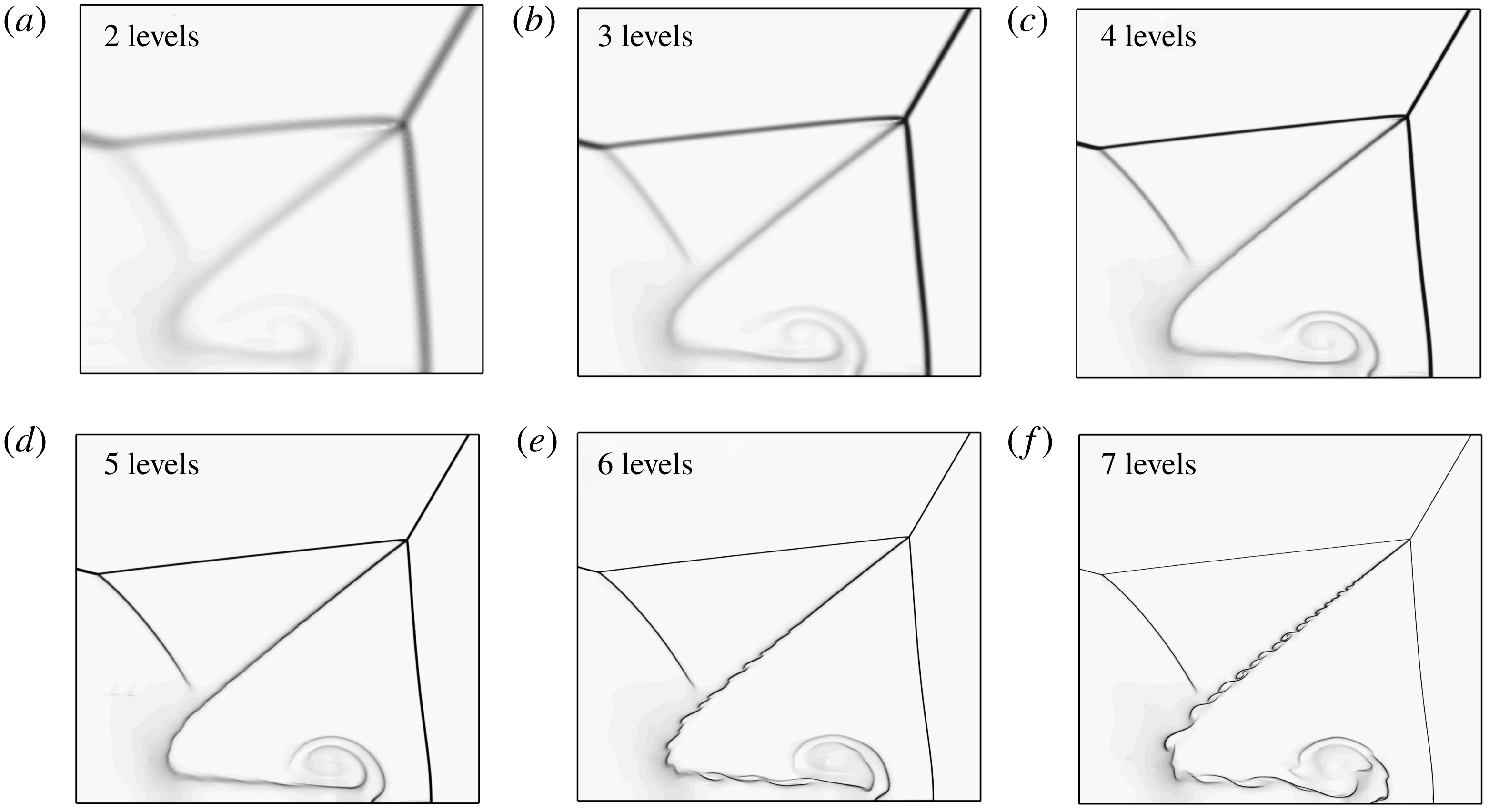
Figure 11 shows the numerical density gradient contours of a double Mach reflection flow obtained under different mesh refinement levels. Clearly, with the increase of mesh refinement level, shock waves and contact interfaces become sharper. The vortices along the slipstream and wall jet as a result of Kelvin–Helmholtz instability reveal themselves when the refinement level reaches 6 and higher. The original grid number is
 $50\times 140$
. With 2, 3, 4, 5, 6 and 7 levels of mesh refinement, the total grid numbers increase into approximately 18k, 26k, 58k, 110k, 190k and 320k, respectively.
Trajectory angles of first triple point (a) and deformation extents of the Mach stem (b) with different mesh refinement levels.

Because we are interested in Mach stem deformation, we take two characteristic parameters to examine mesh convergence – the trajectory angle of the first triple point,
 $\unicode[STIX]{x1D712}$
, and the deformation extent of the Mach stem,
 $f$
, as shown in figure 12. It can be found that the two parameters converge to certain values with an increase of the mesh refinement level, and when the refinement level is greater than 4, the deviations of
 $\unicode[STIX]{x1D712}$
and
 $f$
become trivial. The relative errors of the parameters between level 6 and level 7 are no more than 0.5 %.
The above results also indicate that K–H vortices have little influence on the deformation of the Mach stem as long as the main (time-averaged) features of the wall jet and roll-up vortex are captured.
Considering the reliability of both the flow patterns and the values of the key parameters, all simulations use a mesh refinement level of 6.



