


1. Introduction
According to the idea of “uninterruptible maintenance,” if the electrical power supply system malfunctions, it is an urgent issue for all power supply departments and continuously promotes the live operation of the distribution network [Reference Menendez, Auat Cheein, Perez and Kouro1–Reference Alhassan, Zhang and Shen4]. One of the most frequent procedures used in both routine and urgent power grid maintenance is cable stripping [Reference He, Wang and Ruan5]. Traditional manual procedures using knives have been used, but they have unavoidable drawbacks such as the potential for electrical shock and the ease with which the inner metal core can be damaged [Reference Chen, Liu and Dong6–Reference Li and Yi7]. In order to avoid manual labor, an automatic cable insulation peeling mechanism must be created. A variety of robot types utilized in power transmission lines have been created in recent years [Reference Pouliot and Richard8–Reference Jing, Liao and Zhang16], although none of them focused on cable stripping, they still give us some lessons.
For the maintenance of electrical live power lines, R. Aracil et al. [Reference Aracil, Ferre and Hernando17] designed a telerobot called “ROBTET.” Two master arms at the operator’s working station are used to control the ROBTET system semi-automatically. An experimental prototype of a live maintenance robot with customizable terminal function for high-voltage transmission lines was created by Jiang Wei et al. [Reference Jiang, Wu and Fan18]. The replacement of the insulator strings and tightening of drainage board bolts will be handled by the robot system. For live-line suspension insulator strings in 345 kV power transmission lines, Joon-Young Park et al. developed a straightforward, small-sized, and lightweight wheel-leg robot [Reference Park, Lee and Cho19]. Through the use of two sensing rods, the robot system measured the distribution voltage and the insulation resistance of an insulator. For the purpose of inspecting electricity transmission lines, a semi-automated robot was designed by Chithamacharyulu PV et al. [Reference Chithamacharyulu, Sashanka and Kiran20]. A cutting-edge power transmission line maintenance robot for broken strand repair was created by Yifeng Song et al. [Reference Song, Wang, Jiang and Ling21]. The robot fastens the broken strand firmly using a specific clamp, has passive joints, and can move along the OGW and cross counterweights. For four split high-voltage transmission lines, Hong Jun Li et al. designed a drainage plate maintenance robot and suggested a reliable trajectory tracking motion control approach using sliding mode variable structure control theory [Reference Li, Jiang and Zou22]. In order to repair insulator strings, spacers, maintain dampers, and replace drainage plates, Jiang Wei et al. studied the power maintenance robot [Reference Jiang, Ye and Yan23]. By using kinematics modeling and analysis of the working area based on the Monte Carlo approach, the mechanical structure of the robot was optimized. For a particular class of under-actuated power-line inspection robots, Gerasimos Rigatos et al. suggested a nonlinear optimum control approach [Reference Rigatos, Zervos and Siano24].
Although the aforementioned power transmission line maintenance robots had a number of capabilities, cable stripping was not one of them. Therefore, the mechanism design and analysis of a novel 10 kV cable stripping robot are the main topics of this study. The following are the contents of this essay: The structure design of the wire stripping robot is introduced in Section 2, the electromagnetic shielding design and simulation are carried out in Section 3, the finite element simulation of important parts is discussed in Section 4, the rigid-flexible coupling analysis is discussed in Section 5, and the experiment to confirm the effectiveness of the designed cable stripping robot is carried out in Section 6.
2. Structural design of the cable stripping robot
There are two different types of stripping techniques: rotary cutting and vertical cutting [Reference Jalil, Leone, Martinelli, Moroni, Pascali and Berton25–Reference Xie, Liu, Xu and Zhang27]. The vertically cut stripper, which consists of the upper tool base and the lower tool base, is shown in its basic form in Fig. 1. The tool is propelled downward by its top and lower bases, and cutting is accomplished by the longitudinal movement of the tool down the cable. The rotating cable stripping schematic diagram is shown in Fig. 2. The wire around the cable is peeled using a rotary cutting knife. The force is transmitted longitudinally as a result of the rotary cutting knife tilting in one direction.
Schematic diagram of vertically stripping cable.

Schematic diagram of rotary stripping cable.

The inner aluminum stranded wire is easily cut using the vertically stripping cable method if the upper and lower base feeding are shallow, or there will be unclean stripping phenomena if the upper and lower base feeding are deep. Additionally, a lot of force is needed to move the upper and lower tool bases, and the base takes up a lot of room. The stripper becomes more complicated if a long longitudinal stripper is required since it must move the entire wire independently.
Because the force is transferred along the cable path, the rotary stripping cable technique can achieve continuous wire stripping. In addition, the robot is smaller and more portable than the direct cutting and stripping operation, and the mechanism requires less degrees of freedom. As a result, the rotational stripping method is used in the cable stripping robot that is built in this work.
The novel wire stripper robot shown in Fig. 3 is made up of a main motor rotation mechanism, a V-type collet lifting mechanism, and a tool rest lifting mechanism. V-type collet lifting mechanism is for cable clamping. An infrared sensor is built into the tool rest lifting mechanism, which enables automatic feeding according to sensor detection findings, and cable stripping under the rotating cutting force of the main motor rotating mechanism. The robot has a specific wiring channel inside, and the control line employs shielded twisted pair wire, which has a good anti-electromagnetic interference effect.
Overall appearance and structure of the cable stripping robot.

The main motor rotating mechanism and V-collet lifting mechanism transmission diagram are shown in Fig. 4(a) and (b). The DC reduction motor used in the primary motor rotating mechanism drives the driving gear, which in turn causes the driven gear to rotate. In order to achieve the cable stripping action, the V-type collet lifting mechanism is fitted on the collet mounting base, clamps the cable through the screw drive, and then rotates around the cable with the large gear.
Transmission diagram for the V-type collet lifting mechanism and the rotating mechanism.

The V-type collet lifting mechanism’s working principle is as follows: the V-type collet lifting mechanism’s motor forces the positive and negative screw to rotate, driving the V-type collet and guiding collet near to or far away through the two cutting flange nuts. When the cable is clamped, the motor locks itself through position control, resulting in a constant clamping force.
The internal construction diagram for the main motor’s spinning mechanism is shown in Fig. 5. The tool rest raising mechanism and the V-collet lifting mechanism always revolve in the same direction because the motor causes the driving gear to rotate, and one end of the driving gear is connected with a one-way bearing. Together, the open gear and the half gear make a complete driven gear. A screw holds the open gear and half gear together. The electric slip ring can perform command communication between the main motor and the main control board as well as power supply from battery to the motors of the tool rest lifting mechanism and the V-shaped collet lifting mechanism.
Structure drawing of main motor gearbox.

The main motor transmission mechanism works as follows: before stripping the wire, open the half gear around the connecting bolt, insert the cable into the through hole of the rotating mechanism cable, then close the half gear, which is driven by the motor, the driving gear and the open gear meshing transmission, finally drive the rotation of the fastening mechanism, and then drive the cutting mechanism to rotate, so that wire stripping can be realized along the cable.
The transmission diagram for the tool rest lifting mechanism is shown in Fig. 6. The tool rest lifting mechanism works as follows: first, the cutting tool is set on top of the cutting tool rest, the direction is on the cable, screw and cutting tool rest are fixed, the gear sleeve is outside the screw and threaded through the internal hole and screw thread match, driven gear is threaded through the flat key and screw shaft for circumferential connection, the active gear and driven gear meshing connection. As a result, driven by the motor, the operation causes the active gear to revolve, which causes the driven gear, screw shaft to rotate, resulting in screw up and down movement and cutting tool feed and retreat. At the same time, the cutting depth of the tool is primarily controlled by a color sensor mounted on the top of the cutting tool rest, which collects gray value data from the wire core and insulating skin, and then compares and analyzes the gray value of the two. When the color sensor detects silver and white metal inside the cable, a high-level signal is supplied to the controller, and the controller instructs the cutting motor to cease feeding, allowing the cutting mechanism to be precisely positioned.
Drive diagram of tool rest lifting mechanism.

3. Electromagnetic shielding design and simulation for robot control box
The electromagnetic isolation can be produced by embedding the control components in the shielding body, which is formed of conductive or magnetic materials. The electromagnetic shielding efficiency of magnetic and electric fields should be taken into account individually [Reference Möller and Klinkenbusch28].
The electric field shielding efficiency SE E is:
 \begin{equation} SE_{\mathrm{E}}=20\log _{10}\frac{E_{0}}{E_{1}} \end{equation}
where E 0 is the electric field strength at a specific location without shielding; E 1 is the electric field strength while shielding somewhere.
The magnetic field shielding efficiency SE H is:
 \begin{equation} SE_{\mathrm{H}}=20\ln \frac{H_{0}}{H_{1}} \end{equation}
where H 0 is the magnetic field strength at a specific location without shielding; H 1 is the magnetic field strength when shielding somewhere.
As shown in Fig. 7, the robot control box is reduced to a hollow box with dimensions of length a, width b, height c, and wall thickness t.
The formula for calculating the efficiency of a shield is:
 \begin{equation} SE=R+A+M \end{equation}
where R is the single reflection loss on the surface of the shield; A is the absorption loss of shielding material; M is multiple reflection loss.
The shield surface’s lone reflection loss in the electric field is:
 \begin{equation} R_{\mathrm{E}}=3.217+10\log _{10}\left(\frac{\sigma _{\mathrm{r}}}{f^{3}r^{3}\mu _{\mathrm{r}}}\right) \end{equation}
Anti-electromagnetic resistance of the robot control box schematic diagram.

In a magnetic field, a shield’s single reflection loss is:
 \begin{equation} R_{\mathrm{H}}=20\log _{10}\left(5.35r\sqrt{\frac{f\sigma _{\mathrm{r}}}{\mu _{\mathrm{r}}}}\right)+0.354+\frac{117}{r}\sqrt{\frac{\mu _{\mathrm{r}}}{f\sigma _{\mathrm{r}}}} \end{equation}
where r is the distance from the field source to the shielding material; f is electromagnetic wave frequency;
 $\mu_{r}$
is the relative permeability;
 $\sigma_{r}$
is the relative conductivity.
The absorption loss of shielding material is:
 \begin{equation} A=131.43t\sqrt{f\mu _{\mathrm{r}}\sigma _{\mathrm{r}}} \end{equation}
The internal multiple reflection loss M of the shield is:
 \begin{equation} M=10\log _{10}\left[1-2\times 10^{-0.1\mathrm{A}}\cos \left(0.23A\right)+10^{-0.2\mathrm{A}}\right] \end{equation}
The formula demonstrates how M and A are connected. when A > 15 dB, M can be ignored, and the thickness of shielding material of robot control box can be obtained as follows:
 \begin{equation} t=\frac{SE-R-M}{131.43\sqrt{f\mu _{\mathrm{r}}\sigma _{\mathrm{r}}}} \end{equation}
It is calculated that if the shielding material reaches 80 dB shielding efficiency at 50 Hz power frequency, the material thickness meets t > 1.2 mm, and the thickness is set at 1.5 mm, the electric field intensity in the control system of the robot under the 10 kV overhead line will be less than 4 kV/m.
The electric and magnetic fields of the robot control box are simulated in Maxwell software in order to assess the shielding effectiveness of the control box material in 10 kV overhead lines.
Apply the solution domain to the model, create a region for the control box, and then apply to the grid in order to simulate the electric field of the control box when the nominal cross-section of a 10 kV overhead aluminum stranded conductor is 150 mm2. Finally, set the solution. The solution error is 1, and the maximum number of iteration steps is 10. Figure 8 displays the pretreatment of the aluminum alloy material control box after the setting is complete.
Include the excitation conditions after pretreatment. Analyze the cable’s electric field potential first under typical 10 kV conditions. When we apply a 10 kV voltage to the three wires and the chassis’ outer layer, Fig. 9 depicts the potential distribution.
Control box pretreatment diagram.

Distribution diagram of 10 kV potential in x-z direction of control box.

The control box’s potential value progressively decreases from the middle to the middle at 10 kV, and the potential value there is significant, according to the 10 kV potential distribution diagram for the control box. Additionally, it’s important to examine the control box’s electric field shielding and distribution.
To solve the electric field, provide 10 kV voltage to the three overhead cables and the chassis’ outer layer. The findings of the distribution of the electric field in the robot control box, insulated by the robot, which are depicted in Fig. 10.
Distribution diagram of 10 kV electric field in x-z direction of the control box.

Although the middle area has a stronger electric field shielding effect, the control box’s effect at the two conductor holes is marginally worse. Since the total electric field strength is less than the maximum of 4 kV/m, the shielding effect is effective and satisfies the robot’s operational needs.
Three cables can be subjected to 350 A of line current when the nominal conductor section is 150 mm2. Figure 11 displays the control box’s magnetic field dispersion.
Distribution diagram of 350 A current magnetic field in x-z direction of the control box.

The magnetic field in the core of the cable reaches 0.0056 T, as shown by the control box’s magnetic field distribution diagram under current of 350 A. The magnetic field’s strength steadily lowers all around, and the shield contributes in some measure to its shielding. Due to leakage from two wire holes at the top and bottom of the control box, the magnetic induction strength in the control box increases, but the total magnetic field strength of the control box satisfies standard working requirements.
4. The robot control box analysis
4.1. Finite element analysis
Modal analysis is a crucial step in the design of a gear fixed box because it identifies the mechanical structure’s natural frequency and vibration mode as well as its vibration characteristics [Reference Elshazly, Kassem and Elshafei29]. The gear fixed box model is imported into the workbench for modal analysis after any necessary processing, and the material of the gear fixed box is set to FR-4 epoxy resin. The fixing limits can be put on the bolt holes at the bottom of the model because the bottom of the gear fixing box is connected to the adapter fixing seat by bolts. Figure 12 depicts the boundary conditions of the gear fixing box. Because the gear pair is susceptible to low-order vibrations, Workbench was used to analyze the modal results of the first 20 steps of the gear fixing box, as shown in Table I.
Diagram of the gear fixed housing’s boundary conditions.

The first 20 order natural frequencies.

The modal vibration modes of the gear fixed box of orders first to sixth are shown in Fig. 13. The study reveals that swing and torsion are primarily the modal vibration modes of the gear fixed box.
Initial six modal mode shape diagrams.

The left-right swing of the top dominates the first-order modal shape of the gear fixed box, with a maximum displacement of 361.89 mm; the left-right torsional deformation of the box’s top prevails the second-order modal shape, with a maximum displacement of 475.2 mm; and the left-right swing of the right part of the box dominates the third-order modal shape, with a maximum displacement of 350.38 mm. The maximum displacement of the gear fixed box’s fourth-order modal deformation, which is primarily the upper and lower torsional deformation of the box’s top, is 595.18 mm. The maximum displacement of the gear fixed box’s fifth-order modal vibration mode is 361.65 mm. The maximum displacement of the gear fixed box’s sixth-order modal vibration mode is primarily the box body swinging left and right. The gear fixed box will not resonate when its natural frequency and excitation frequency have the following relationship.
 \begin{equation} 0.75\omega _{0}\lt \omega \lt 1.3\omega _{0} \end{equation}
where
 $\omega_0$
is the natural frequency;
 $\omega$
is the excitation frequency.
The gear fixed box deforms just slightly when excited at 47.384 ∼ 349.34 Hz. The box body primarily swings and twists when excited at 372.35 ∼ 967.31 Hz. The box body primarily exhibits local protrusion and swing deformation when excited at 1017.4 ∼ 1713.6 Hz. Local protrusion and swing are the vibration mode that has the highest likelihood of causing the box to resonate; hence, this vibration mode should be avoided as much as possible in the design.
The motor chosen for this study has seven poles and a rated speed of 469 rpm. We can infer that the motor input shaft rotates at 54.7 Hz, which is essentially lower than the box’s natural frequency. The driven wheel’s output conversion frequency, which can be calculated based on the number of teeth, is 18.2 Hz, which is far lower than the box’s minimal natural frequency. Resonance will be prevented since the gear meshing frequency, 765.8 Hz is between the eighth and ninth modes.
4.2. Rigid-flexible coupling analysis of robot control box
The main motor spinning mechanism won’t deform elastically in an ADAMS simulation if it is treated as a pure rigid body for dynamic analysis, but deformation in the experiment is unavoidable [Reference Inalpolat and Kahraman30]. Full flexibility of the mechanism will require a lot of calculations; thus, stiff flexible coupling study of the robot’s entire model is done before flexibility analysis of the gear fixed box of the primary motor rotational mechanism.
Mesh creation and parameter settings. After importing the model into ANSYS APDL, modify the FR-4 material properties. The center of the supporting hole of the driving wheel and the driven wheel is chosen as the node because a connection between the flexible body and the stiff body is necessary. Figure 14 illustrates the final precision of 2.0 meshing of the parts and nodes.
Flexible body meshing model.

Establish the slave node component using the internal measurement of the driving wheel and the driven wheel support hole, set up the master node component, and create a rigid area for the fixed box as illustrated in Fig. 15. The master-slave node establishes the rigid area, and then the mnf type file is output.
Rigid areas of the box body.

In order to obtain the rigid-flexible coupling model, Adams’ rigid-flexible coupling model must be replaced, and new constraints and drives must be added, as shown in Fig. 16.
Rigid-flexible coupling virtual prototype model.

The dynamic solution is run after the model is created. The dynamic meshing force is serviced by using the function step (time, 0,0,1,1,180*d*time) to cause the drive wheel to revolve the v-type lifting mechanism at a speed of 180°/s after 1 s. 500 simulation steps are used, and the simulation time is t = 12 s. Check the stress nephogram of the gear fixed box in the post-processing after the simulation, as illustrated in Fig. 17.
The robot simulation process’s maximum stress, as determined by the stress nephogram, is 5.12 × 10⁵ N/m2. After the rigid-flexible replacement, Adams receives the stress data from ANSYS. The top 10 hot locations with the highest stress are listed in Table II.
Top ten hot items in the gear fixed box.

Stress diagram of gear fixed box.

The chart shows that when the gear fixed box’s maximum stress at 0.672 s, the 3501 node reaches 512,036 N/m2, and the material strength needs are combined with the stress nephogram analysis. The tensile strength of the FR-4 epoxy resin used to make the gear fixed box, which may meet the material’s strength criteria, is 375 Mpa. Choose the gear fixed box’s maximum stress node 3501 for analysis, and the node stress curve is displayed in Fig. 18.
Strain diagram of node 3501.

The robot’s startup causes the most stress since the motor’s instantaneous impact causes the robot to have a significant impact dynamic load. The robot should refrain from often starting up and shutting down while it is functioning in order to preserve the gear fixed box’s service life and prevent damage.
It is required to assess the impact of the stiff and flexible replacement of the gear fixed box on the meshing force of the gear pair. Figure 19 depicts the primary motor rotational mechanism’s gear pair’s circumferential meshing force curve.
Curve of circumferential meshing force of gear pair.

Since the gear meshing force will be impacted by the high speed at the starting stage and the contact deformation of the flexible body will cause the sudden change to occur at the maximum expected speed, it can be seen from the curve of circumferential meshing force that the gear pair reaches the maximum meshing force of 7.5 N at the motor starting stage. The gear pair begins to rotate at a consistent speed and the mechanism functions steadily after the speed reaches the anticipated value after 0.5 s.
Figure 20 depicts the radial meshing force curve for the gear pair of the main motor’s rotating mechanism. The stiff flexible coupling dynamic analysis shows that the gear pair’s fluctuating meshing force has no effect on the mechanism’s functioning, proving the logic of the wire stripping robot’s structural design.
Curve of radial meshing force of gear pair.

5. Prototype and experimental tests
Figure 21 depicts the prototype cable stripping robot that is created for this paper. The main rotating mechanism, the V-type collet lifting mechanism, and the tool rest lifting mechanism all use DC brushless geared motors of type M2006 from DJI Corp Motors of type M3508 and M2006 are driven by electronic governors RoboMaster C620 and C610, respectively. Table III displays the main characteristics of the cable stripping robot.
Figure 22 depicts the experimental setup described in this work. The upper computer transmits a signal to the main control board, which controls the robot body, via radio frequency communication with the main control board. The higher computer also receives sensor and motor status information from the main control board.
Structural parameters of the robot.

Prototype of the robot.

Experimental system of wire stripping robot for live operation.

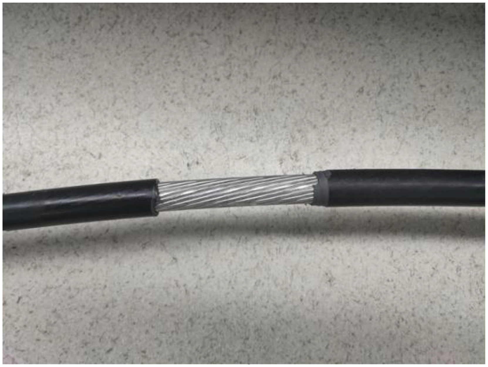
The working item is a 10 kV high-voltage wire with a cross-sectional size of 240 mm2. The upper computer issues the start command, and the robot then starts the stripping process. In Fig. 23, the experimental procedure is depicted. The appearance of the stripped cable is depicted in Fig. 24. The robot performs reasonably well overall in the stripping test, and the amount of damage to the cable skin is minimal, which is in accordance with the design specifications. The three-part robot mechanism’s speed responses are shown in Fig. 25. The maximum actual speed of the primary motor’s rotating mechanism is 82.98 rpm, which is 15.25% faster than the 72 rpm referenced velocity in a stable functioning state. In a stable operating condition, the V-type collet-lifting mechanism should rotate at 18 rpm; however, it actually turns at 30.54 rpm. The tool rest raising mechanism’s reference speed is –12 rpm, but its actual speed is –6.6 rpm. Large tracking mistakes are brought on by severe external force interference brought on by hard cable insulation peeled off.
Experimental test of wire stripping robot.

Appearance of the 240 mm2 cable with skin removed by the robot.
Speed responses of the robot stripping on the cable with cross-section area of 240 mm2.

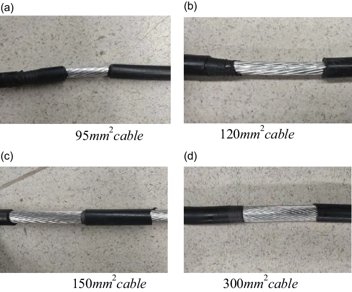
In order to further verify the reliability of the experiment of the wire stripping robot system, cable stripping experiments were conducted on 95, 120, 150, and 300 mm2 cables. After the tests, the appearance of each cable is shown in Fig. 26. Twenty-five groups of test results were extracted to record the stripping length, stripping time, and cable damage. The stripping test data are shown in Table IV. Twenty-five groups of test results Stripping length is 10 cm, the average stripping length is 9.7cm/min, stripping speed is moderate, can maintain the stability of the system. According to the cable damage, the cable damage condition is good, the integrity rate is more than 75%, and the system reliability is good.
Stripping test data.

Appearance after the cable skin is peeled off.
6. Conclusion and future work
6.1. Conclusions
The autonomous high-voltage wire stripping robot’s mechanical structure is designed in this article. The robot control system will experience electromagnetic interference as a result of the 10 kV power grid environment. As a result, the robot control box’s shield is constructed and simulated. The fixed box of the robot is subjected to a modal analysis in order to examine potential resonance phenomena. Additionally, a stiff flexible coupling analysis of the entire structure is conducted in light of the potential deformation of the gear fixed box during robot operation, which could have an impact on the performance as a whole. Through live stripping tests on a cable with 95, 120, 150, 240, and 300 mm2 cross-sectional area, the system’s functionality is examined, and the stability of the wire stripping robot is proved by damage degree analysis. The high-voltage stripping robot developed in this study helps to increase the effectiveness of live repair work on power grids.
6.2. Future work
Peeling hard cable insulation causes external force interference, which causes high speed tracking inaccuracies during operation. This will make it difficult to manipulate the knife in the tool rest raising mechanism and harm the cable’s aluminum rubber core. Thus, in the course of further research, more sophisticated robot control algorithms should be examined.
Required declarations
Author contributions
Jun Zhong: Conceptualization, Revise draft. Zhichao Wang: Design controller and revise draft. Shaoguang Hu: Design robot, Writing origin draft. Zhenfeng Han: Methodology, Supervision.
Financial support
This work is supported in part by National Natural Science Foundation of China ( 52275285), Science and technology planning projects of Changzhou (CE20215052).
Conflicts of interest
The authors declared no potential conflicts of interest with respect to the research, authorship, and publication of this article.
Ethical approval
Not applicable.



