
Introduction
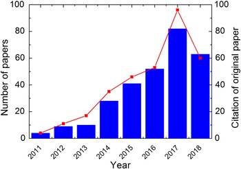
Ferroelectric properties in fluorite-structure oxides were first reported in 2011 by Böscke et al. and have since attracted increasing interest in the field of ferroelectricity and nonvolatile memories.[Reference Böscke, Müller, Bräuhaus, Schröder and Böttger1–Reference Schroeder, Yurchuk, Müller, Martin, Schenk, Polakowski, Adelmann, Popovici, Kalinin and Mikolajick6] Figure 1 shows the variations in the annual number of papers on fluorite-structure ferroelectrics and the annual citations of the original paper by Böscke et al.[Reference Böscke, Müller, Bräuhaus, Schröder and Böttger1] since 2011. As shown in the figure, the number of papers is rapidly increasing, and more than 100 papers are expected to be published in 2018 despite 8 years short history of fluorite-structure ferroelectrics. Various applications, such as ferroelectric memories,[Reference Mikolajick, Slesazeck, Park and Schroeder3, Reference Müller, Yurchuk, Schlösser, Paul, Hoffmann, Mueller, Martin, Slesazeck, Polakowski, Sundqvist, Czernohorsky, Seidel, Kücher, Boschke, Trentzsch, Gebauer, Schröder and Mikolajick7–Reference Mulaosmanovic, Slesazeck, Ocker, Pešić, Muller, Flachowsky, Müller, Polakowski, Paul, Jansen, Kolodinski, Richter, Piontek, Schenk, Kersch, Kuenneth, van Bentum, Schroder and Mikolajick10] energy harvesters,[Reference Park, Kim, Kim, Moon, Kim and Hwang11, Reference Hoffmann, Schroeder, Künneth, Kersch, Starschich, Böttger and Mikolajick12] electrostatic supercapacitors,[Reference Hoffmann, Schroeder, Künneth, Kersch, Starschich, Böttger and Mikolajick12–Reference Kim, Lee, Gwon, Kim, Kim, Moon, Hyun, Park, Park and Hwang14] electrocaloric coolers,[Reference Park, Kim, Kim, Moon, Kim and Hwang11, Reference Hoffmann, Schroeder, Künneth, Kersch, Starschich, Böttger and Mikolajick12, Reference Park, Kim, Kim, Moon, Kim, Lee, Hyun and Hwang15, Reference Park, Schenk, Hoffmann, Knebel, Gärtner, Mikolajick and Schroede16] and pyroelectric sensors,[Reference Smith, Kitahara, Rodriguez, Henry, Brumbach and Ihlefeld17, Reference Jachalke, Schenk, Park, Schroeder, Mikolajick, Stöcker, Mehner and Meyer18] have been suggested for fluorite-structure ferroelectrics due to their advantages over the conventional perovskite-structure ferroelectrics. Ferroelectric memories with ferroelectric doped HfO2 have also been suggested to be useful for neuromorphic devices and random-number generators.[Reference Mulaosmanovic, Ocker, Müller, Noack, Müller, Polakowski, Mikolajick and Slesazeck19, Reference Mulaosmanovic, Mikolajick and Slesazeck20]
Annual number of papers (blue bars, left y-axis) and annual citations of the original paper (Ref. Reference Böscke, Müller, Bräuhaus, Schröder and Böttger1, red dots, right y-axis) on fluorite-structure ferroelectrics (source: Google Scholar, June 6th, 2018). The result was searched using keywords ((HfO2) or (hafniumoxide) or (hafniumdioxide) or (ZrO2) or (zirconiumoxide) or (zirconiumdioxide)) and ((ferroelectric) or (piezoelectric) or (pyroelectric)), and irrelevant results were manually screened out. It should be noted that the only the number of papers and citations until June 6 is shown in 2018.

The ferroelectric memory is one of the most important applications of fluorite-structure ferroelectrics.[Reference Scott21–Reference Koo, Seo, Kim, Shin, Lee, Baik, Lee, Lee, Bae, Lim, Yoo, Park, Kim, Han, Baik, Choi, Park and Park23] Two spontaneous polarization states can be written electrically, and the written states can be retained even without power supply. The write speed and energy efficiency are sufficiently high for realizing a nonvolatile random access memory. As a result, ferroelectrics have been considered as a promising material for future memory devices. One version of a memory device based on ferroelectrics is the capacitor-based ferroelectric random access memory (FeRAM), whose cell generally consists of one transistor and one capacitor (1T-1C). Its overall structure is very similar to that of a dynamic random access memory (DRAM), except that the capacitive layer of the capacitor was replaced by a ferroelectric material, and the plate line of FeRAM does not remain at a constant voltage, as in DRAM, but needs to be pulsed to switch the ferroelectric polarization. The addition of the plate line increases the capacitive load during the read-write operations, limiting the access speed, and additionally complicates the layout of the memory.
Due to the limited memory array size of perovskite-based FeRAM capacitors, the commercialization of FeRAM is currently limited to niche markets. Further scaling is not possible due to the high physical thickness of the perovskite layer (typically ~70 nm) and the inability to create three-dimensional (3D) capacitors, as in DRAM.[Reference Koo, Seo, Kim, Shin, Lee, Baik, Lee, Lee, Bae, Lim, Yoo, Park, Kim, Han, Baik, Choi, Park and Park23] The state-of-the-art technology node is still 130 nm,[Reference Mikolajick, Slesazeck, Park and Schroeder3, 24, Reference Okuyama, Park, Ishiwara, Okuyama, Sakai and Yoon25] a value one order of magnitude higher than the values of the current technology nodes of DRAM and NAND flash memory. Such a large feature size limits the use of the devices for applications where a high operation speed and low power consumption are essential, due to the much higher cost per bit compared to DRAM and NAND flash memory combined at the equivalent functionality. Other critical issues will be reviewed in the next section.
The fluorite-structure ferroelectrics are expected to resolve most of the aforementioned critical issues of perovskite-structure ferroelectrics. In fact, HfO2 and ZrO2, the two most frequently studied fluorite-structure materials in the semiconductor field, are already being utilized as the materials for the gate oxide layer of the logic field effect transistors (FETs) and the dielectric layers of the DRAM capacitors, respectively.[Reference Hwang26] Thus, matured atomic layer deposition (ALD) techniques are already available. Simply adding a rapid thermal process for the appropriate crystallization of HfO2 or ZrO2 thin films prompts ferroelectric behavior in these materials. Nonetheless, the fluorite-structure ferroelectrics still have several issues that need to be resolved before they can be adopted for memory applications. Among these, the problems of the wake-up effect and insufficient endurance are critical, and numerous studies have been conducted on these issues. In this review paper, therefore, the aforementioned reliability issues of fluorite-structure ferroelectrics for memory applications are intensively reviewed, and perspectives for resolving such issues are provided based on the data published in the recent literature.
Advantages of fluorite-structure ferroelectrics over conventional ferroelectrics for memory applications
In the case of the conventional Pb(Zr,Ti)O3(PZT)- or SrBi2Ta2O9(SBT)-based 1T-1C FeRAMs using planar capacitors, the main scaling issue is the limited availability of charge for stable sensing. According to Maruyama et al.[Reference Maruyama, Kondo, Singh and Ishiwara27], at least double remanent polarization (2Pr) of 84 µC/cm2 is required for a stable operation of a 1T-1C FeRAM with a 90 nm technology node. For practical polycrystalline PZT thin films, 2Pr is limited to <~80 µC/cm2, and other polycrystalline ferroelectrics, such as SBT and (Bi,La)4Ti3O12 (BLT), have even lower 2Pr values.[Reference Lines and Glass28] BiFeO3 (BFO) can have 2Pr values above 200 µC/cm2 and was suggested as a solution to extend the scalability.[Reference Maruyama, Kondo, Singh and Ishiwara27] BFO's low bandgap and associated large leakage current,[Reference Shuai, Zhou, Streit, Reuther, Bürger, Slesazeck, Mikolajick, Helm and Schmidt29] however, limit its practical application in memory devices. The 2Pr values of perovskite-structure ferroelectrics are usually degraded at several-tens-of-nm-scale devices due to the damaging effect of the side wall regions, which may be caused by the patterning processes.
Therefore, the fabrication of 3D nanoscale capacitors is essential to overcome the scaling issue of 1T-1C FeRAM. There are several critical issues, however, with regard to the fabrication of 3D capacitors based on the conventional ferroelectrics. The first issue is the difficulty of depositing perovskite-structure ferroelectrics with two or more cation components in high-aspect-ratio structures via ALD. There have been several reports on the ALD of perovskite-structure oxide, but it is very difficult to achieve sufficient ferroelectric properties for memory applications using ALD.[Reference Watanabe, Hoffmann-Eifert, Peter, Mi, Jia, Hwang and Waser30, Reference McDaniel, Ngo, Hu, Posadas, Demkov and Ekerdt31] The even more fundamental issue is the scaling of the physical thickness of ferroelectric thin films. To fabricate 3D capacitors, the total thickness of the capacitor needs to be smaller than ~1/3 the technology node. The thickness of the conventional perovskite-structure ferroelectrics, however, is limited to 50–70 nm to achieve robust ferroelectricity.[Reference Ihlefeld, Harris, Keech, Jones, Maria and Trolier-McKinstry32] As a result, the conventional perovskite-structure ferroelectrics cannot be utilized for the sub-130 nm technology node. There have been extensive discussions on the critical thickness of the ferroelectric properties of perovskite-structure materials because the ferroelectric properties of perovskite oxides have been experimentally shown to become degraded with decreasing thickness below a certain level.[Reference Tybell, Ahn and Triscone33–Reference Sai, Kolpak and Rappe36] It is now accepted that the ferroelectric properties can be retained even with several atomic layers’ thickness for epitaxial films grown on selective single-crystalline substrates. Such films lack complementary metal oxide semiconductor (CMOS) compatibility, however, and are thus not suitable for mass production.[Reference Tybell, Ahn and Triscone33–Reference Sai, Kolpak and Rappe36] Nonetheless, in practical metal-ferroelectric-metal capacitors that have ferroelectric materials with a polycrystalline structure, degradation of the ferroelectric properties with decreasing film thickness is generally observed. Until now, there is no fabrication method that is known to integrate single-crystalline perovskite structures into CMOS devices, and to maintain defect-free properties up to the end of the integration process.
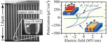
As mentioned earlier, FeRAM based on perovskite-structure ferroelectrics cannot be scaled down to below 130 nm, but the ferroelectric HfO2-based film can make a breakthrough and achieve 3D capacitors. Polakowski et al.[Reference Polakowski, Riedel, Weinreich, Rudolf, Sundqvist, Seidel and Müller37] reported the ferroelectric properties of the TiN/Al:HfO2/TiN-based deep-trench capacitors with a P r per projected area of 152 µC/cm2. Figure 2 shows a cross-sectional transmission electron microscopy (TEM) image of the fabricated deep-trench capacitor with Al:HfO2 (left panel) and its projected polarization-electric field (P-E) curve (right panel).[Reference Polakowski, Riedel, Weinreich, Rudolf, Sundqvist, Seidel and Müller37] Although the Pr value of the planar capacitor was only 15 µC/cm2, the 1.6-μm-deep-trench capacitor with an aspect ratio of 13:1 could increase the Pr per projected area by one order of magnitude, which is very close to the degree of increase of the capacitor area.[Reference Polakowski, Riedel, Weinreich, Rudolf, Sundqvist, Seidel and Müller37] To date, the largest Pr value ever reported for fluorite-structure (planar) ferroelectrics is 45 µC/cm2 for a La:HfO2.[Reference Müller, Yurchuk, Schlösser, Paul, Hoffmann, Mueller, Martin, Slesazeck, Polakowski, Sundqvist, Czernohorsky, Seidel, Kücher, Boschke, Trentzsch, Gebauer, Schröder and Mikolajick7] If this film is grown in the previous 3D capacitor structure, a Pr of ~450 µC/cm2 per projected area can be achieved.
Cross-sectional TEM image (left panel) and projected polarization-electric field curve (right panel) of the 3D TiN/Al:HfO2/TiN capacitor. In the right panel, A and B are width and length of the projected area, respectively, so the projected area can be calculated from (A × B). Adapted with permission from Ref. Reference Müller, Böscke, Müller, Yurchuk, Polakowski, Paul, Martin, Schenk, Khüllar, Kersch, Weinreich, Riedel, Seidel, Kumar, Arruda, Kalinin, Schlösser, Böschke, van Bentum, Schröder and Mikolajick9 (IEEE, 2013).

The scaling limit of HfO2-based FeRAM can be estimated through a simple calculation.[Reference Pešić, Schroeder and Mikolajick38] Using HfO2-based ferroelectrics, a FeRAM capacitor can be fabricated with dimensions similar to those of a DRAM capacitor, since the equivalent material (HfO2) is being utilized as a capacitive layer. Therefore, a potential scaling limit can be estimated through simple comparison with the state-of-the-art DRAM. The amount of charge that can be stored in a DRAM capacitor (Q) can be calculated using the simple equation Q = ε 0 ε rV/t, where ε 0, ε r, V, and t are the permittivity of vacuum, the dielectric constant of the dielectric layer, the operation voltage, and the film thickness, respectively. For the DRAM capacitors, the ε r, V, and t are roughly 20, 0.5 V, and 6 nm, respectively. With these values, the charge on a DRAM capacitor is calculated to be approximately 1.5 µC/cm2, which is about 5–10% of the 2Pr value of ferroelectric-HfO2-based films with a similar film thickness. With a polarization value that is more than one order of magnitude higher, HfO2-based FeRAMs are expected to scale better than DRAM. For the practical scaling of FeRAMs, however, the effect of the film thickness needs to be carefully examined especially if the required film thickness is below 5 nm.
Two other types of ferroelectric memories, the ferroelectric field effect transistor (FeFET) and the ferroelectric tunnel junction (FTJ), have also been considered promising candidates.[39] FeFET is a simple nonvolatile memory cell consisting of only a single transistor, where the gate oxide layer of the metal-oxide-semiconductor FET was replaced by a ferroelectric layer. Depending on the polarization orientation, the threshold voltage is modulated, and information can be directly stored in a 1 T memory cell. Unlike in FeRAM, the data stored in FeFET can be read non-destructively. FTJ is based on the tunneling conduction of electrical carriers through an extremely thin ferroelectric layer (generally a few nm level), and the tunneling current density is determined by the polarization direction of the ferroelectric layer relative to the configuration of the two different electrodes. FTJ is also considered as a promising candidate for the next-generation nonvolatile memory, but it also has critical issues that are not easy to overcome. For practical device fabrication with a large wafer area (300 mm in diameter), it is very difficult to have a uniform thickness over the entire area. As FTJ is based on the tunneling conduction mechanism, only small thickness non-uniformity in atomic scale can make significant differences. Even worse, for uniform device performance, precise control of the interface property between the thin ferroelectric layer and the semiconductor or electrode layers is critical. To simplify the device design and to relax the requirements for the ferroelectric layer, an alternative structure with additional tunneling (dielectric) layer was proposed. In the structure, the polarization is switched in the ferroelectric, but the tunneling current is limited by a thin tunneling layer.[Reference Fujii, Kamimuta, Ino, Nahasaki, Takaishi and Saitoh40–Reference Pesic, di Lecce, Hoffmann, Mulaosmanovic, Max, Schröder, Slesazeck, Larcher and Mikolajick42] Several issues, however, including the insufficient read current, still need to be resolved before putting such structure in practical memory arrays. Thus, FeFET is considered a nearer-future candidate compared with FTJ. Accordingly, in this review, the focus is mainly on the capacitor-based 1T-1C FeRAM and FeFET devices.
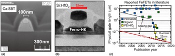
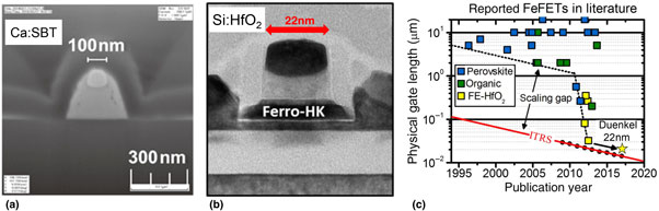
The conventional perovskite-structure ferroelectrics have been intensively studied to date, but the perovskite-based FeFETs still have critical issues. First, Si compatibility is more important for FeFET than for 1T-1C FeRAM because in the former, the ferroelectric layer is in direct contact with the Si channel. The conventional ferroelectric materials, such as PZT, SBT, and BLT, are not Si-compatible, and interface reactions like silicate formation prevent them from having direct contact with Si, and further deter any high-temperature procedure afterward. Additionally, in a FET arrangement, the ferroelectric will be in a serial connection with the depleted channel capacitance. As perovskite-structure ferroelectrics have very high ε r in the range of a few hundred, the applied voltage is divided in an unbalanced manner. This voltage divider effect becomes even more severe when a low-ε r interfacial layer is formed between the ferroelectric layer and the Si channel to avoid the aforementioned interfacial reactions, and a severe depolarization field is generated in the retention condition as a result.[Reference Okuyama, Park, Ishiwara, Okuyama, Sakai and Yoon25, Reference Ma and Han43, Reference Schroeder, Slesazeck, Mikolajick, Park, Ishiwara, Okuyama, Sakai and Yoon44] Several methods, such as the insertion of a high-k buffer layer below the ferroelectric layer and replacing the Si channel with an oxide semiconductor, have been suggested to resolve this issue.[Reference Okuyama, Park, Ishiwara, Okuyama, Sakai and Yoon25, Reference Schroeder, Slesazeck, Mikolajick, Park, Ishiwara, Okuyama, Sakai and Yoon44–Reference Takahashi and Sakai47] Figure 3(a) shows a cross-sectional TEM image of a FeFET with a Ca:SBT ferroelectric and a HfO2 buffer layer on a Si substrate.[Reference Hai, Takahashi, Zhang and Sakai48] The HfO2 buffer layer was inserted to prevent low-quality interface formation between Ca:SBT and the Si substrate.[Reference Hai, Takahashi, Zhang and Sakai48] It is noteworthy that a HfO2 or doped HfO2 layer was also used as a high-ε r buffer layer due to its good Si compatibility.[Reference Schroeder, Slesazeck, Mikolajick, Park, Ishiwara, Okuyama, Sakai and Yoon44–Reference Hai, Takahashi, Zhang and Sakai48] The best retention properties for FeFET with the conventional ferroelectrics have been reported with a rather thick SBT ferroelectric in combination with a HfO2-based buffer layer.[Reference Schroeder, Slesazeck, Mikolajick, Park, Ishiwara, Okuyama, Sakai and Yoon44–Reference Hai, Takahashi, Zhang and Sakai48]
Cross-sectional TEM images of a FeFET with (a) Ca:SBT and (b) Si:HfO2 ferroelectric gate oxide layer, respectively. (c) Physical gate length of logic FETs and FeFETs in the literature. Figure 3(a) was reproduced from Ref. Reference Hai, Takahashi, Zhang and Sakai48 with permission (The Japan Society of Applied Physics, 2015), and Fig. 3(b) and 3(c) were reproduced from Ref. Reference Dünkel, Trentzsch, Richter, Moll, Fuchs, Gehring, Majer, Wittek, Müller, Melde, Mulaosmanovic, Slesazeck, Müller, Ocker, Noack, Löhr, Polakowski, Müller, Mikolajick, Höntschel, Rice, Pellerin and Beyer49 with permission (IEEE, 2017).

Figure 3(b) shows the cross-sectional TEM image of a FeFET with a ferroelectric-Si:HfO2 thin film with a 22 nm technology node.[Reference Dünkel, Trentzsch, Richter, Moll, Fuchs, Gehring, Majer, Wittek, Müller, Melde, Mulaosmanovic, Slesazeck, Müller, Ocker, Noack, Löhr, Polakowski, Müller, Mikolajick, Höntschel, Rice, Pellerin and Beyer49] Unlike the SBT-based FeFET in Fig. 3(a), the thickness of the ferroelectric layer and the gate length can be reduced by ~80%. It is important to note that the memory window (MW) of a FeFET is determined by the voltage margin for switching ferroelectric polarization, which can be estimated as MW = 2E c×t Fe, where E c is the coercive field, and t Fe is the thickness of the ferroelectric layer. As a result, the rather low E c of perovskite-structure ferroelectrics (typically 50–100 kV/cm) will require a very thick ferroelectric in the 100 nm range. This, in turn, significantly limits the scalability of a FeFET device based on perovskite-structure ferroelectrics.[Reference Park, Lee, Kim, Kim, Moon, Kim, Müller, Kersch, Schroeder, Mikolajick and Hwang2–Reference Schroeder, Yurchuk, Müller, Martin, Schenk, Polakowski, Adelmann, Popovici, Kalinin and Mikolajick6, Reference Schroeder, Slesazeck, Mikolajick, Park, Ishiwara, Okuyama, Sakai and Yoon44] Therefore, a high E c of fluorite-structure ferroelectrics with a 0.8–2.0 MV/cm range is more advantageous for FeFET applications. Figure 3(c) shows the scaling in the physical gate length of logic FET and FeFET over a period of about 20 years. As shown in the figure, there was a technology gap of one to two orders of magnitude between logic FET and FeFET before the adoption of fluorite-structure ferroelectrics, but the gap almost disappeared after the introduction of ferroelectric HfO2. Currently, the smallest reported technology node for FeFET is 22 nm.[Reference Dünkel, Trentzsch, Richter, Moll, Fuchs, Gehring, Majer, Wittek, Müller, Melde, Mulaosmanovic, Slesazeck, Müller, Ocker, Noack, Löhr, Polakowski, Müller, Mikolajick, Höntschel, Rice, Pellerin and Beyer49]
The high E c together with the rather low ε r of ferroelectric HfO2 can significantly improve the retention of FeFET,[Reference Gong and Ma50] which has been the most critical issue for FeFETs with conventional perovskite-structure ferroelectrics. To date, the best retention property reported for a conventional material was the use of an SBT-based FeFET with a HfAlOx buffer layer [Fig. 4(a)].[Reference Takahashi and Sakai47] As shown in the figure, the retention was measured for a period of 37 days, and an extrapolated I on/I off ratio of 104 after 10 years was achieved.[Reference Takahashi and Sakai47, Reference Takahashi, Aizawa, Park and Ishiwara51] Figure 4(b) shows the retention test result of the FeFET with ferroelectric Si:HfO2.[Reference Yurchuk, Müller, Paul, Schlösser, Martin, Hoffmann, Müeller, Slesazeck, Schröeder, Boschke, van Bentum and Mikolajick52] As shown in the figure, a memory window of 0.9 V was extrapolated after 10 years, and even at 200 °C, a memory window of 0.2 V was retained. Despite its short development time of only 8 years, the retention property of HfO2-based FeFET is comparable with or even better than the best-reported retention properties from the perovskite-based FeFETs. It is important to note that on the integrated memory arrays of 28 and 22 nm technology nodes, comparable retention data were achieved.[Reference Pešić, Knebel, Hoffmann, Richter, Mikolajick and Schroeder8, Reference Dünkel, Trentzsch, Richter, Moll, Fuchs, Gehring, Majer, Wittek, Müller, Melde, Mulaosmanovic, Slesazeck, Müller, Ocker, Noack, Löhr, Polakowski, Müller, Mikolajick, Höntschel, Rice, Pellerin and Beyer49]
Retention test results for FeFETs with (a) an SBT/HfAlO gate oxide layer and (b) a Si:HfO2 gate oxide layer, respectively. Figure 4(a) was reproduced from Ref. Reference Takahashi and Sakai47 with permission (The Japanese Society of Applied Physics, 2005), and Fig. 4(b) was reproduced from Ref. Reference Müller, Böscke, Müller, Yurchuk, Polakowski, Paul, Martin, Schenk, Khüllar, Kersch, Weinreich, Riedel, Seidel, Kumar, Arruda, Kalinin, Schlösser, Böschke, van Bentum, Schröder and Mikolajick9 with permission (IEEE, 2013).

The spatially inhomogeneous distribution of E c of polycrystalline fluorite-structure ferroelectrics can be another potential issue for scaled FeFETs. Since the lateral grain diameter of ALD grown fluorite-structure ferroelectrics are generally comparable with their film thickness, only a few grains are expected to present in the gate stack of a scaled 28 or 22 nm device. Each grain may have a different E c for switching, resulting from a different orientation or the inhomogeneity of the material. The grain size dependent coercive field is also known for perovskite structure ferroelectrics.[Reference Genenko, Zhukov, Yampolskii, Schütrumpf, Dittmer, Jo, Kungl, Hoffmann and von Seggern53] Accordingly, a different region within the channel may have a slightly different threshold voltage, leading to the stepwise switching of the devices.[Reference Mulaosmanovic, Slesazeck, Ocker, Pešić, Muller, Flachowsky, Müller, Polakowski, Paul, Jansen, Kolodinski, Richter, Piontek, Schenk, Kersch, Kuenneth, van Bentum, Schroder and Mikolajick10, Reference Mulaosmanovic, Ocker, Müller, Schroeder, Müller, Polakowski, Flachowsky, van Bentum, Mikolajick and Slesazeck54] Hence, if the grain distribution cannot be precisely controlled, the threshold voltage distribution, which is strongly related to the E c distribution in the ferroelectric layer, of scaled devices can increase as scaling proceeds.[Reference Dünkel, Trentzsch, Richter, Moll, Fuchs, Gehring, Majer, Wittek, Müller, Melde, Mulaosmanovic, Slesazeck, Müller, Ocker, Noack, Löhr, Polakowski, Müller, Mikolajick, Höntschel, Rice, Pellerin and Beyer49] With further scaling, however, FinFET or gates around the structures are necessary, where the effective gate area is larger compared with the planar devices, which will mitigate this issue.
Fluorite-structure ferroelectrics have other advantages over perovskite-structure ferroelectrics for memory applications. For perovskite materials like PZT, special electrode materials such as Ir, IrO2, and SrRuO3 are required to show reliable properties.[Reference Setter, Damjanovic, Eng, Fox, Gevorgian, Hong, Kingon, Kohlstedt, Park, Stephenson, Stolitchnov, Taganstev, Taylor, Yamada and Streiffer55] In layered perovskites like SBT, this is not necessary, but due to the complicated crystal structure of SBT, a very high thermal budget for annealing is necessary, leading to severe problems in integration, specifically for the stacked 1T-1C memory cells.[Reference Pinnow and Mikolajick56] The metal nitride electrodes, however, which are the standard electrode materials in the semiconductor industry, can be utilized for fluorite-structure ferroelectrics. This will improve the cost-effectiveness and CMOS compatibility of fluorite-structure ferroelectrics. Furthermore, Park et al. reported that the ferroelectric (Hf,Zr)O2 (HZO) film could endure the adverse effect of hydrogen annealing,[Reference Park, Kim, Kim, Lee, Kim and Hwang57] whereas the ferroelectric properties of perovskite oxides could be seriously degraded by hydrogen annealing.[Reference Hartner, Bosk, Schindler, Bachhofer, Mört, Wendt, Mikolajick, Dehm, Schroeder and Waser58, Reference Aggarwal, Perusse, Tipton, Ramesh, Drew, Venkatesan, Romero, Podobedov and Weber59] TiN does not bear the catalytic activity of dissociating the H2 molecules into the H atoms, which is the case for the Pt electrode for the conventional perovskite-structure ferroelectrics, making TiN/HZO/TiN even more robust against the H2 effect.[Reference Park, Kim, Kim, Lee, Kim and Hwang57]
Remaining issues in fluorite-structure ferroelectrics
In the previous section, the advantages of fluorite-structure ferroelectrics over the conventional perovskite-structure ferroelectrics for ferroelectric memories were reviewed. This section will discuss the remaining issues in fluorite-structure ferroelectrics for the same applications, the wake-up effect, and endurance (or fatigue), which will be dealt with in the sections Wake-up effect and Limited endurance, respectively. The other critical issue in ferroelectric memories is imprint, which is the tendency of a ferroelectric to stabilize the state it is stored in, and leads to a loss of retention of the opposite state.[Reference Rodriguez, Remack, Gertas, Wang, Zhou, Boku, Rodriguez-Latorre, Udayakumar, Summerfelt and Moise60] The imprint effect is generally associated with charge trapping at the defect sites related to oxygen vacancies, but to date, only basic studies have been conducted on this topic for doped HfO2 ferroelectrics.[Reference Florent, Lavizzari, Di Piazza, Popovici, Duan, Groeseneken and Van Houdt61, Reference Pešić, Schroeder, Slesazeck and Mikolajick62] As fatigue and imprint generally have the same origin,[Reference Lo63, Reference Fengler, Hoffmann, Slesazeck, Mikolajick and Schroeder64] it is expected that the imprint would be improved when the other reliability issues such as wake-up effect and endurance are mitigated. Therefore, the main focus in the following two subsections will be on the wake-up effect and endurance issues.
Wake-up effect
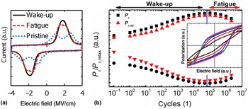
The first critical issue is the so-called “wake-up effect,” which was first studied by Zhou et al. in ferroelectric Si:HfO2 thin films.[Reference Zhou, Xu, Li, Guan, Cao, Dong, Müller, Schenk and Schröder65] This effect can also be observed in perovskite-structure ferroelectrics,[Reference Fengler, Pešić, Starschich, Schneller, Künneth, Böttger, Mulaosmanovic, Schenk, Park, Nigon, Muralt, Mikolajick and Schroeder66] but the number of cycles to the woken-up state of the order of 103 is negligible compared with the overall cycling stability of the order of 1013–1015 as long as the initial Pr is sufficiently high.[Reference Genenko, Glaum, Hoffmann and Albe67] Moreover, optimized PZT films using oxide electrodes show negligible wake-up effect, which is not the case for the HfO2-based ferroelectrics. Figure 5(a) shows the general switching current-electric field curves of ferroelectric-HfO2-based thin films within three different stages (pristine, woken-up, and fatigued) of field cycling, while Fig. 5(b) accordingly shows the changes in Pr. with the increasing number of field cycles. In the pristine state [the blue dotted curve in Fig. 5(a)], the switching current curve has two peaks in both the positive and negative bias regions. This is different from the ideal switching current curve of a ferroelectric, where only a single switching current peak is seen at each E c. During the electric field cycling process, the switching current peaks are merged [the black curve in Fig. 5(a)]. With a further increased number of field cycles, the switchable polarization decreases, which corresponds to the generally observed fatigue in many ferroelectrics.
(a) Current-voltage and the corresponding polarization-voltage characteristics (b inset) of ferroelectric Sr:HfO2 for the pristine, woken-up, and fatigued states. (b) Extracted evolution of the positive and negative remanent polarization with field cycling. The difference between the positive and negative remanent polarization, Pr+/Pr−, is related to the memory window. Adapted from Ref. Reference Pešić, Fengler, Larcher, Padovani, Schenk, Grimley, Sang, LeBeau, Slesazeck, Schroeder and Mikolajick68 with permission (John Wiley and Sons, 2016).

Schenk et al. discussed the possible mechanisms of the splitting of the switching current peaks in the pristine state.[Reference Schenk, Yurchuk, Mueller, Schroeder, Starschich, Böttger and Mikolajick69] First-order reversal curve (FORC) measurement was conducted, and a locally distributed inhomogeneous internal field resulted in a divided switching current peak.[Reference Schenk, Hoffmann, Ocker, Pešic, Mikolajick and Schroeder70] The inhomogeneous internal electric field distribution can originate from the spatially unevenly distributed charged defects, such as oxygen vacancies.[Reference Pešić, Fengler, Larcher, Padovani, Schenk, Grimley, Sang, LeBeau, Slesazeck, Schroeder and Mikolajick68] A high oxygen vacancy concentration is expected to be present near the electrodes due to the reduction of the doped HfO2 layer by the metal nitride electrodes, whose distribution may be mostly asymmetric. The resulting asymmetric distribution of the oxygen vacancies can be an origin of the internal field in the pristine material.[Reference Pešić, Fengler, Larcher, Padovani, Schenk, Grimley, Sang, LeBeau, Slesazeck, Schroeder and Mikolajick68] During the electric field cycling process, the oxygen vacancies may diffuse into the bulk regions of the ferroelectric-HfO2-based films, in which case the wake-up process will occur, accompanied by the merging of the switching current peaks [the black solid curve in Fig. 5(a)].[Reference Pešić, Fengler, Larcher, Padovani, Schenk, Grimley, Sang, LeBeau, Slesazeck, Schroeder and Mikolajick68] In subsequent studies, a redistribution of the charges related to the oxygen vacancies was reported.[Reference Fengler, Hoffmann, Slesazeck, Mikolajick and Schroeder64]
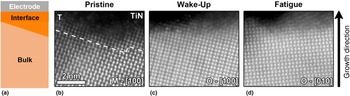
Another mechanism of the wake-up effect can be the field-cycling-induced phase transition. It was Lomenzo et al. who first suggested that the phase transition from the tetragonal (t-) to the ferroelectric orthorhombic phase (o-phase) is the origin of the wake-up effect.[Reference Lomenzo, Takmeel, Zhou, Fancher, Lambers, Rudawski, Jones, Moghaddam and Nishida71] They observed a decrease in the ε r as well as an increase in Pr with an increasing number of electric field cycles. The ε r decrease and Pr increase could be related to a phase transition from a non-ferroelectric higher-ε r phase to a ferroelectric lower-ε r phase. In fluorite-structure ferroelectrics, the phase transition from the t- to the o-phase corresponds to this case.[Reference Lomenzo, Takmeel, Zhou, Fancher, Lambers, Rudawski, Jones, Moghaddam and Nishida71] A similar trend was confirmed in other studies.[Reference Kim, Park, Kim, Lee, Moon, Kim, Hyun and Hwang72, Reference Park, Kim, Kim, Lee, Moon, Kim, Hyun, Fengler, Schroeder and Hwang73] Kim et al. examined the changes in the interfacial capacitance (C i), which originates from the non-ferroelectric interfacial layer, and found that the C i value increased with an increasing number of field cycles, suggesting a decrease in the thickness of the interfacial layer, which is most probably in the t-phase.[Reference Kim, Park, Kim, Lee, Moon, Kim, Hyun and Hwang72] A phase transition from the monoclinic (m-) to the o-phase was observed by Grimley and Schenk et al. using scanning TEM (STEM) and impedance spectroscopy.[Reference Müller, Yurchuk, Schlösser, Paul, Hoffmann, Mueller, Martin, Slesazeck, Polakowski, Sundqvist, Czernohorsky, Seidel, Kücher, Boschke, Trentzsch, Gebauer, Schröder and Mikolajick7, Reference Grimley, Schenk, Sang, Pešić, Schroeder, Mikolajick and LeBeau74] Figure 6 shows (a) a schematic and cross-sectional TEM images of the (b) pristine, (c) woken-up, and (d) fatigued states of the ferroelectric-Gd:HfO2 film near the TiN top electrode. In the pristine state, the interfacial region is highly defective, and the crystalline structure was identified to be the t-phase. On the other hand, the dominant crystalline phase in the bulk region was the m-phase. Ten different regions were analyzed using the STEM to obtain a statistically reliable result, and the overall capacitor performance was analyzed using impedance spectroscopy.[Reference Grimley, Schenk, Sang, Pešić, Schroeder, Mikolajick and LeBeau74] After electric field cycling, the thickness of the highly defective interface significantly decreased, and the dominant crystalline phase of the bulk region changed to the ferroelectric o-phase, as shown in Fig. 6(c). As discussed earlier, in the woken-up state, Pr enhancement was observed, which was well matched with the results of other studies on the wake-up effect. With the onset of fatigue, an increase in the bulk defect density could be confirmed by the increase in the leakage current and the changes in the impedance spectra.[Reference Grimley, Schenk, Sang, Pešić, Schroeder, Mikolajick and LeBeau74]
Single-grain segments of the capacitor stack near the electrode interface. (a) Sketch of the interfacial region next to the electrode. STEM images of doped HfO2 in (b) pristine, (c) woken-up, and (d) fatigued conditions showing relaxation of the bulk monoclinic and tetragonal symmetries at the electrode interfaces towards the ferroelectric phase. This trend is most pronounced in the pristine state and least pronounced in the fatigued state. The intensity levels were adjusted to enhance the contrast near the electrode. Adapted from Ref. Reference Pešić, Fengler, Larcher, Padovani, Schenk, Grimley, Sang, LeBeau, Slesazeck, Schroeder and Mikolajick68 with permission (John Wiley and Sons, 2016).

It should be noted that a migration of oxygen vacancies is not an origin of ferroelectric hysteresis as Shimizu et al. experimentally examined.[Reference Shimizu, Yokouchi, Oikawa, Shiraishi, Kiguchi, Akama, Konno, Gruverman and Funakubo75] They compared ferroelectric properties of Hf0.5Zr0.5O2 thin films annealed under the O2 or N2 atmosphere at various temperatures and switching pulses, and proved that Hf0.5Zr0.5O2 thin films show an intrinsic ferroelectric properties which should originate from the sub-unit-cell motion of ions.[Reference Shimizu, Yokouchi, Oikawa, Shiraishi, Kiguchi, Akama, Konno, Gruverman and Funakubo75] However, according to computational simulation, free energies of various crystalline phases of HfO2 are affected by oxygen vacancy concentration.[Reference Hoffmann, Schroeder, Schenk, Shimizu, Funakubo, Sakata, Pohl, Drescher, Adelmann, Materlik, Kersch and Mikolajick76] According to Hoffmann et al.’s work,[Reference Hoffmann, Schroeder, Schenk, Shimizu, Funakubo, Sakata, Pohl, Drescher, Adelmann, Materlik, Kersch and Mikolajick76] the free energy of high symmetry phases such as the t- and c-phase decreases with increasing oxygen vacancy concentration compared with that of the o-phase in a high oxygen vacancy concentration range of a few %. Such high oxygen vacancy concentration is unreasonable for the entire doped HfO2 thin films but might be possible in the interfacial regions which are generally more defective compared to the bulk region of thin films. Therefore, a local phase evolution during repetitive electric field cycling is a plausible mechanism for the wake-up effect.
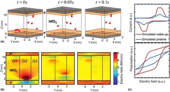
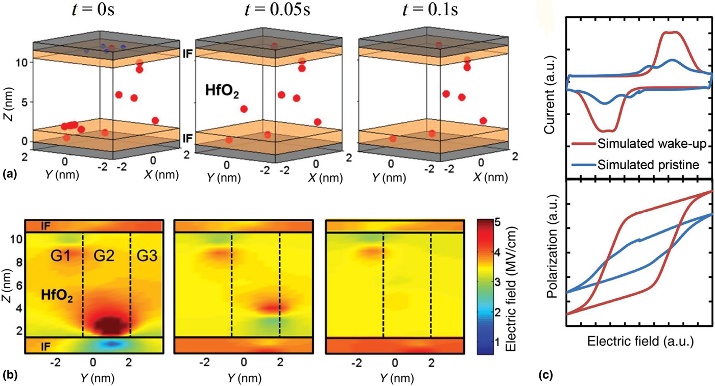
Pešić et al. comprehensively examined the wake-up effect through both an experiment and a computational simulation.[Reference Pešić, Fengler, Larcher, Padovani, Schenk, Grimley, Sang, LeBeau, Slesazeck, Schroeder and Mikolajick68] Figure 7(a) shows the simulation results of the oxygen vacancy distribution in the ferroelectric-HfO2 capacitor at three different times, and Fig. 7(b) depicts the corresponding electric field distribution in the capacitor. Figure 7(c) describes the simulated switching current-voltage and the polarization voltage curve in the pristine and woken-up states. At t = 0 s in Fig. 7(a), the oxygen vacancy concentration is high in the interface regions. As a result, the spatially inhomogeneous electric field can be observed as shown in the left panel of Fig. 7(b). With the increasing number of field cycles, the oxygen vacancies diffuse into the bulk region of the film, and their distribution becomes more homogeneous, as shown in Fig. 7(a). At the same time, the electric field distribution also becomes more homogeneous with an increasing number of field cycles, as seen in Fig. 7(b). With this simple model, the I-V and P-V curves can be simulated as shown in Fig. 7(c).
Simulated wake-up effect of the device: (a) vacancy diffusion and (b) the corresponding electric field evolution within the device with the field cycling of the ferroelectric capacitor at three different points in time at a 4 MV/cm externally applied field. IF represents a low-ε r interfacial layer whereas G1–G3 represent three different grains within the stack. (c) The I-V and P-V characteristics obtained by removing the charges from the interface and changing the k-value of the grains undergoing phase transformation. Adapted from Ref. Reference Pešić, Fengler, Larcher, Padovani, Schenk, Grimley, Sang, LeBeau, Slesazeck, Schroeder and Mikolajick68 with permission (John Wiley and Sons, 2016).
Starschich et al. showed that even a single DC pulse with a sufficient length could wake up the ferroelectric doped HfO2 capacitors.[Reference Starschich, Menzel and Böttger77] Thus, the total pulse length rather than the number of switching cycles may be critical for the wake-up effect, implying that a time-dependent phenomenon such as diffusion may be the origin of such effect. Starschich et al. also showed that both resistive and polarization switching could be observed in a single sample, although an initial forming process was required for resistive switching.[Reference Starschich, Menzel and Böttger78] It is generally accepted that the resistive switching in HfO2 is governed by the formation and rupture of an oxygen vacancy filament, and that the operating electric fields for resistive and ferroelectric switching have the same order of MV/cm. Recently, it was shown that the resistive switching curves of a Sr-doped HfO2 film could show a deep reset after the conduct of significant field cycling in a ferroelectric mode.[Reference Max, Pešić, Slesazeck and Mikolajick79] This could indicate the depletion of oxygen, or in other words, an increase in oxygen vacancy concentration towards the interface.[Reference Schönhals, Rosário, Hoffmann-Eifert, Waser, Menzel and Wouters80] Therefore, it can be deduced that the wake-up effect can be attributed to the diffusion of the oxygen vacancies under the electric field.
The wake-up phenomenon is strongly affected by the annealing temperature. Park et al. reported that the cycle numbers required for waking up HZO thin films decrease with increasing annealing temperature, with an increased Pr in the pristine state.[Reference Park, Kim, Kim, Lee, Moon and Hwang81] At the same time, the field cycle number to a hard breakdown decreased as well.[Reference Park, Kim, Kim, Lee, Moon and Hwang81] Lomenzo et al. also reported that the P-E curves of Si:HfO2 thin films showed stronger pinching when the annealing was performed at a lower temperature of 700 °C, and that the breakdown strength decreased while the leakage current increased for a higher annealing temperature of 900 °C.[Reference Lomenzo, Takmeel, Moghaddam and Nishida82] Both the decrease in breakdown strength and the increase in leakage current are likely related to the reduced number of field cycles until the hard breakdown occurrence. Such a trend was also confirmed by Richter et al. in Si:HfO2 thin films, and by Schroeder et al. in La:HfO2 films.[Reference Richter, Schenk, Park, Tscharntke, Grimley, LeBeau, Zhou, Fancher, Jones, Mikolajick and Schroeder83, Reference Schroeder, Richter, Park, Schenk, Pešić, Hoffmann, Fengler, Pohl, Rellinghaus, Zhou, Chung, Jones and Mikolajick84] Thus, increasing the annealing temperature can degrade the endurance of ferroelectric-HfO2-based films, although it is effective in reducing the wake-up effect.
The doping concentration is another important factor influencing the degree of wake-up effect. Park et al. reported that the wake-up effect could be reduced by optimizing the doping concentration of HZO thin films.[Reference Kim, Park, Kim, Lee, Moon, Kim, Hyun and Hwang72] In their study, a Zr doping concentration slightly lower than that for the largest Pr most effectively optimized the wake-up effect.[Reference Kim, Park, Kim, Lee, Moon, Kim, Hyun and Hwang72] In general, the wake-up effect is less obvious in HfO2 films with a higher doping concentration, which generally shows dielectric or antiferroelectric properties.[Reference Kim, Park, Kim, Lee, Moon, Kim, Hyun and Hwang72, Reference Richter, Schenk, Park, Tscharntke, Grimley, LeBeau, Zhou, Fancher, Jones, Mikolajick and Schroeder83, Reference Schroeder, Richter, Park, Schenk, Pešić, Hoffmann, Fengler, Pohl, Rellinghaus, Zhou, Chung, Jones and Mikolajick84] Another important factor is the electrode material. Hoffmann et al. examined the ferroelectric properties of Gd:HfO2 thin films with TiN or TaN electrodes, and reported that the TaN electrode led to a longer wake-up phase.[Reference Hoffmann, Schroeder, Schenk, Shimizu, Funakubo, Sakata, Pohl, Drescher, Adelmann, Materlik, Kersch and Mikolajick76]
Based on the aforementioned research results, it is very likely that the wake-up effect can be attributed to the diffusion and redistribution of the oxygen vacancies by repetitive electric field cycling. Therefore, the wake-up effect is a thermally activated process whose degree is proportional to the process time and temperature. Starschich et al. showed that the pulse length rather than the number of switching cycles is a key factor causing the wake-up effect,[Reference Starschich, Menzel and Böttger77, Reference Starschich, Menzel and Böttger78] which is consistent with the observation that the wake-up effect is weakened when the annealing temperature is increased. Higher annealing temperature should help distribute the oxygen vacancies more uniformly in the entire film. The effect of the electrode material is not easy to understand, as Park et al. discussed elsewhere, and this topic needs further study.[Reference Park, Schenk, Hwang and Schroeder85]
Limited endurance
Besides the wake-up effect, an insufficient lifetime during field cycling is another critical problem of ferroelectric-HfO2-based thin films. The best field cycling endurance reported to date (4 × 10¹⁰ [Reference Chernikova, Kozodaev, Negrov, Korostylev, Park, Schroeder, Hwang and Markeev86]) in the ferroelectric-HfO2-based thin film is much smaller than that in the conventional perovskite-based ferroelectrics (1015 for the MSP430 FR573x microcontroller, Texas Instruments). In general, the failure mechanism of ferroelectric-HfO2-based thin films is a hard breakdown after a significant increase in the leakage current.[Reference Böscke, Müller, Bräuhaus, Schröder and Böttger1, Reference Kim, Park, Kim, Lee, Moon, Kim, Hyun and Hwang72, Reference Lomenzo, Takmeel, Moghaddam and Nishida82–Reference Schroeder, Richter, Park, Schenk, Pešić, Hoffmann, Fengler, Pohl, Rellinghaus, Zhou, Chung, Jones and Mikolajick84, Reference Park, Kim, Kim, Jeon, Moon and Hwang87] This effect is then followed by polarization fatigue, a mechanism that has also been observed in perovskite-structure ferroelectrics.
The smaller number of field cycles to break down for ferroelectric-HfO2-based films is a natural consequence of such films’ high E c relative to their breakdown field strength. The E c value of ferroelectric HfO2 is generally in the range of ~0.8–2.0 MV/cm, which is higher by ~one order of magnitude than that of perovskite thin films.[Reference Park, Lee, Kim, Kim, Moon, Kim, Müller, Kersch, Schroeder, Mikolajick and Hwang2, Reference Schroeder, Yurchuk, Müller, Martin, Schenk, Polakowski, Adelmann, Popovici, Kalinin and Mikolajick6, Reference Clima, Wouters, Adelmann, Schenk, Schroeder, Jurczak and Pourtois88] As a result, to achieve a saturated P-E curve, a field equal to or higher than ~3 MV/cm needs to be applied. The apparent (extrinsic) breakdown strength of HfO2 is generally ~5 MV/cm.[Reference Migita, Ota, Yamada, Sawa and Toriumi89] Therefore, the applied electric field for polarization switching is ~60–80% of the breakdown strength, suggesting an inherently small margin in securing the allowed number of field cycles before the breakdown. The intrinsic breakdown strength, however, was suggested to be ~20 MV/cm without any involvement of defective factors like oxygen vacancies.[Reference Wang90] Such high intrinsic field to breakdown (E bd) leaves room for improving the limited endurance through defect engineering. In a normal experiment, nevertheless, the breakdown of the oxide materials is always governed by extrinsic factors.
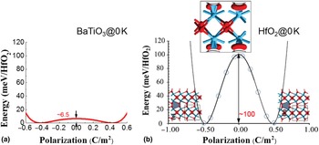
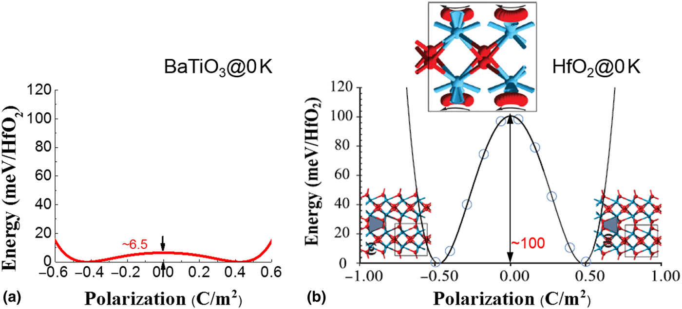
The higher E c value of ferroelectric-HfO2-based films can be attributed to the higher kinetic energy barrier between the two spontaneous polarization states. Figure 8(a) and 8(b) show the free energy curves of tetragonal BaTiO3 and orthorhombic HfO2 from computational simulations. BaTiO3 has a 6.5 meV/f.u. kinetic energy barrier while o-phase HfO2 has ~100 meV/f.u..[Reference Clima, Wouters, Adelmann, Schenk, Schroeder, Jurczak and Pourtois88, Reference Lu, Li and Cao91] A similar kinetic energy barrier was reported for o-phase HfO2 by other researchers.[Reference Huan, Sharma, Rossetti and Ramprasad92, Reference Barabash, Pramanik, Zhai, Magyari-Kope and Nishi93] Although the switching kinetics is generally governed by the reverse-domain nucleation and growth, the electric field required for polarization switching is expected to be affected by the kinetic energy barrier between the two spontaneous polarization states.
Free energy polarization curve of (a) tetragonal BaTiO3 and (b) orthorhombic HfO2 at 0 K. Figure 8(b) was adapted from Ref. Reference Clima, Wouters, Adelmann, Schenk, Schroeder, Jurczak and Pourtois88 with permission (AIP Publishing LLC, 2014).
The hard breakdown event after an increase in leakage current is generally attributed to the formation of a permanent conducting path possibly due to the accumulation of defects such as oxygen vacancies.[Reference Pešić, Fengler, Larcher, Padovani, Schenk, Grimley, Sang, LeBeau, Slesazeck, Schroeder and Mikolajick68] It is generally known that oxygen vacancies tend to accumulate near defects like grain boundaries.[Reference McKenna and Shluger94] In the case of the ferroelectric o-phase HfO2 thin films, a polycrystalline nature with a nanoscale grain size is generally observed.[Reference Kim, Lee, Gwon, Kim, Kim, Moon, Hyun, Park, Park and Hwang14, Reference Starschich, Menzel and Böttger78, Reference Schroeder, Richter, Park, Schenk, Pešić, Hoffmann, Fengler, Pohl, Rellinghaus, Zhou, Chung, Jones and Mikolajick84, Reference Park, Kim, Lee, Kim, Moon, Kim, Hyun and Hwang95–Reference Mueller, Mueller, Singh, Riedel, Sundqvist, Schroeder and Mikolajick101] Such small grain size results in a high grain boundary area-to-volume ratio, indicating that the oxygen vacancies can reach the grain boundaries and accumulate there, with a short diffusion distance. Therefore, increasing the grain size can be a promising method of improving the endurance of ferroelectric HfO2-based thin films. The effect of the grain size on endurance, however, has not yet been carefully studied. On the other hand, in many previous studies, it was shown that increasing the grain size could result in an increased m-phase fraction due to the weakened interface/grain boundary energy effect. Therefore, there may be a trade-off between optimizing the non-ferroelectric m-phase fraction and endurance.
The doping concentration also affects the endurance of doped HfO2 or HZO thin films. Figure 9(a) shows the changes in the 2Pr and endurance of HZO thin films for various Zr/(Hf + Zr) ratios. The largest 2Pr of 40 µC/cm2 could be observed for the 0.5 Zr/(Hf + Zr) ratio, but this composition showed the smallest number of switching cycles to a hard breakdown. The effect of the doping concentration on the breakdown of the HfO2 film has not yet been clearly elucidated to date. In many previous studies, however, it was reported that the HfO2 thin film with a higher doping concentration, resulting in dielectric or antiferroelectric properties, could endure longer than the film with a composition that renders the largest Pr.[Reference Kim, Park, Kim, Lee, Moon, Kim, Hyun and Hwang72, Reference Lomenzo, Takmeel, Moghaddam and Nishida82, Reference Richter, Schenk, Park, Tscharntke, Grimley, LeBeau, Zhou, Fancher, Jones, Mikolajick and Schroeder83]
(a) Changes in 2Pr (left axis) and endurance (right axis) with a varying Zr/(Hf + Zr) ratio of(Hf,Zr)O2 thin films. (b) Endurance test results for 10-nm-thick Hf0.5Zr0.5O2 films annealed at 400–600 °C. Figure 9(b) was adapted from Ref. Reference Park, Kim, Kim, Jeon, Moon and Hwang87 with permission (John Wiley and Sons, 2014).

Based on the observation that the endurance of antiferroelectric films is superior to the endurance of ferroelectrics, Pešić et al. suggested a clever method of utilizing antiferroelectric films for nonvolatile memory applications.[Reference Pešić, Knebel, Hoffmann, Richter, Mikolajick and Schroeder8, Reference Schenk, Hoffmann, Ocker, Pešic, Mikolajick and Schroeder70] Generally, antiferroelectrics cannot be utilized for nonvolatile memory applications because its Pr is zero when no field is applied, but shifting the P-E curve of antiferroelectric materials by intentionally inducing a high internal electric field will enable nonvolatile memory storage. The internal bias field can be generated either by using asymmetric electrodes or by adding additional fixed charges in the dielectric layer stack through the combination of different dielectrics.[Reference Pešić, Li, Di Lecce, Hoffmann, Materano, Richter, Max, Slesazeck, Schroeder, Larcher and Mikolajick102] With this method, antiferroelectric ZrO2 could have a reasonable Pr value even at zero electric field.[Reference Pešić, Hoffmann, Richter, Mikolajick and Schroeder103] Although its Pr value is smaller than that of the ferroelectric Hf0.5Zr0.5O2 film, the E c value, which is another critical factor for endurance, can be significantly lowered as well.[Reference Fengler, Nigon, Muralt, Grimley, Sang, Sessi, Hentschel, LeBeau, Mikolajick and Schroeder104]
Based on the preceding observations, it can be stated that decreasing the oxygen vacancy concentration may be another pathway for improving the endurance, which can deter the generation of permanent conducting paths between the top and bottom electrodes. Decreasing the annealing temperature is a potential way to achieve this goal, which can be understood from the observation that a higher annealing temperature resulted in a lower number of switching cycles to break down.[Reference Park, Kim, Kim, Lee, Moon and Hwang81–Reference Schroeder, Richter, Park, Schenk, Pešić, Hoffmann, Fengler, Pohl, Rellinghaus, Zhou, Chung, Jones and Mikolajick84, Reference Park, Kim, Kim, Jeon, Moon and Hwang87] Figure 9(b) shows the endurance test results of Hf0.5Zr0.5O2 thin films annealed at 400–600 °C for 30 s in an N2 atmosphere.[Reference Park, Kim, Kim, Jeon, Moon and Hwang87] Although the Pr decreased at the lower annealing temperature, the 400 °C-annealed sample lasted the longest among the three samples.
Fabricating ferroelectric-HfO2-based films with the preferred orientation or with a high ferroelectric phase fraction should also be beneficial for endurance improvement. The polar axis of the ferroelectric o-phase is the c-axis. Thus, an uncompensated polarization charge at the grain boundaries between two different orientations can induce the accumulation of trapped charges or charged defects such as oxygen vacancies. Moreover, a highly oriented film is expected to have a narrower distribution of E c values, which can decrease the electric field required for a saturated P-E curve. This can also be applied to the phase boundary between the ferroelectric and non-ferroelectric phases. The existence of phase and domain boundaries in nanoscale grains in ALD-grown doped HfO2 thin films was confirmed by Grimley et al. based on the STEM results they had obtained.[Reference Park, Kim, Kim, Lee, Moon, Kim, Hyun, Fengler, Schroeder and Hwang73, Reference Fengler, Nigon, Muralt, Grimley, Sang, Sessi, Hentschel, LeBeau, Mikolajick and Schroeder104]
Figure 10 summarizes the Pr and endurance of ferroelectric-HfO2-based films from the existing literature. In general, the number of endurable cycles decreases with increasing 2Pr value. Therefore, this phenomenon can be called “Pr-endurance dilemma”. The largest endurance value to date of 4.0×10¹⁰ was reported for La:Hf0.5Zr0.5O2 (La:HZO) thin films with a maximum Pr value of 15 µC/cm2.[Reference Chernikova, Kozodaev, Negrov, Korostylev, Park, Schroeder, Hwang and Markeev86] Figure 10(b) shows the endurance test result for the La:HZO thin film.[Reference Chernikova, Kozodaev, Negrov, Korostylev, Park, Schroeder, Hwang and Markeev86] La doping in the HZO film decreased the leakage current, which contributed to the enhanced endurance. The data points in Fig. 10(a), however, are quite scattered, suggesting that further research is necessary to achieve a more thorough understanding of this matter.
(a) Pr-endurance plot from the existing literature. The data were taken from the literature [undoped: Reference Mittmann, Fengler, Richter, Park, Mikolajick and Schroeder96,Reference Polakowski and Mueller105; Si: Reference Schroeder, Yurchuk, Müller, Martin, Schenk, Polakowski, Adelmann, Popovici, Kalinin and Mikolajick6,Reference Mueller, Summerfelt, Muller, Schroeder and Mikolajick106–Reference Mueller, Muller, Hoffmann, Yurchuk, Schlosser, Boschke, Paul, Goldbach, Herrmann, Zaka, Schroder and Mikolajick108; Al: Reference Polakowski, Riedel, Weinreich, Rudolf, Sundqvist, Seidel and Müller37; Si and Al: Reference Mueller, Muller, Schroeder and Mikolajick107; Zr: Reference Park, Kim, Kim, Lee, Moon, Kim, Hyun, Fengler, Schroeder and Hwang73,Reference Chernikova, Kozodaev, Negrov, Korostylev, Park, Schroeder, Hwang and Markeev86,Reference Mueller, Muller, Hoffmann, Yurchuk, Schlosser, Boschke, Paul, Goldbach, Herrmann, Zaka, Schroder and Mikolajick108; Gd: Reference Schroeder, Richter, Park, Schenk, Pešić, Hoffmann, Fengler, Pohl, Rellinghaus, Zhou, Chung, Jones and Mikolajick84; La:HZO: Reference Chernikova, Kozodaev, Negrov, Korostylev, Park, Schroeder, Hwang and Markeev86]. (b) The best endurance result from the La:Hf0.5Zr0.5O2 thin films with three different fatigue pulse height values. Figure 10(b) was adapted from Ref. Reference Chernikova, Kozodaev, Negrov, Korostylev, Park, Schroeder, Hwang and Markeev86 with permission (ACS Publications, 2018).

Finally, it is important to note that almost all the studies described in the literature were performed using large-scale test capacitors with high capacitance. Moreover, the endurance test is normally performed using the standard needles, which need to come in contact with the device. As a result, the electrical stress on the device is significantly higher than the electrical stress an integrated capacitor or FeFET structure would experience in a memory array. Therefore, the absolute number of endurable field cycles, in particular, will increase in a realistic 1T-1C memory cell. To obtain a better impression of the achievable endurance specification, measurement data from integrated 1T-1C arrays will be highly desirable, but these are not yet available in the literature. For FeFET, in contrast, the memory window is much more limited by charge trapping and decreases significantly to below the cycle number, leading to fatigue or breakdown.[Reference Yurchuk, Mueller, Martin, Slesazeck, Schroeder and Mikolajick111]
Conclusion
In this perspective paper, fluorite-structure ferroelectrics were reviewed for memory applications. Compared with the conventional perovskite-structure ferroelectrics, fluorite-structure ferroelectrics have numerous advantages. They are Si- and CMOS-compatible and can have strong ferroelectricity for a sub-10 nm film thickness. As a result, films can be scaled down for simple integration in the FeFET or FeRAM capacitor applications to the technology nodes in the 20 nm range. For a 1T-1C FeRAM application, fluorite-structure ferroelectrics enable 3D capacitors with Pr values sufficient for reliable operation with a state-of-the-art sense amplifier. The sub-10 nm thickness is another significant merit of the 3D capacitor structure. For FeFET application, fluorite-structure ferroelectrics can have sufficient retention for nonvolatile memory application (10 years) due to their lower depolarization field attributed to their low ε r of ~30–35, lower than the ε r of perovskite-structure ferroelectrics.
There are remaining issues, however, regarding fluorite-structure ferroelectrics. The first issue is the wake-up effect, which is believed to result from the non-uniform high oxygen vacancy concentration near the interface adjacent to the electrodes and/or from the phase transition during electric field cycling. Based on the experimental observations in previous studies, the wake-up effect has been attributed to the diffusion and redistribution of the oxygen vacancies or charges in thin films. The temperature and the time-dependent charging of these films can cause imprint effects. The other critical issue regarding fluorite-structure ferroelectrics is their insufficient endurance, which is attributed to a relatively high E c-to-breakdown field strength ratio. The general failure mechanism is a hard breakdown after a significant leakage current increase, which is known to result from the formation of a permanent conducting path possibly due to the accumulation of oxygen vacancies at the grain boundaries. Finally, imprint, another critical issue in ferroelectric memory devices, is by far less intensively studied in fluorite-structure ferroelectrics than in the conventional ferroelectrics. In perovskite-structure ferroelectrics, however, the imprint improvement is based on measures similar to those for endurance improvement because both are caused by the oxygen-vacancy-related defects, which are also critical for the wake-up effect and endurance of fluorite-structure ferroelectrics. To overcome the aforementioned issues, various methodologies were suggested in this study based on the reported experimental observations.
Acknowledgment
CSH acknowledges the support given by the Global Research Laboratory Program (2012 1A1A2040157) of the National Research Foundation of the South Korean government. TM and US acknowledge the EFRE fund of the European Commission and the Free State of Saxony (Germany). MHP was supported by Humboldt Postdoctoral Fellowship from Alexander von Humboldt Foundation.