





1 Introduction
Extensional flow occurs when a fluid experiences a deformation in the streamwise direction and can be observed in many different situations such as flow passing through contractions (Afonso et al. Reference Afonso, Oliveira, Pinho and Alves2011) and expansions (Pinho, Oliveira & Miranda Reference Pinho, Oliveira and Miranda2003; Alves & Poole Reference Alves and Poole2007) and at stagnation point flows like flow through intersections (such as T- shaped (Soulages et al. Reference Soulages, Oliveira, Sousa, Alves and McKinley2009) or cross-slot (Arratia et al. Reference Arratia, Thomas, Diorio and Gollub2006) geometries) or flow passing an obstacle (Bisgaard Reference Bisgaard1983; Walters & Tanner Reference Walters and Tanner1992; Alves, Pinho & Oliveira Reference Alves, Pinho and Oliveira2001; McKinley Reference McKinley2002). Many industrial processes deal with highly extensional flows of polymeric fluids. In most of these cases, a purely elastic instability occurs that is absent for its equivalent Newtonian creeping flow (Poole et al. Reference Poole, Alves, Afonso, Pinho and Oliveira2007a ; Zilz et al. Reference Zilz, Schäfer, Wagner, Poole, Alves and Lindner2014). During the last few decades, significant attention has been placed on such flows to characterize the physics behind these types of instabilities especially in shear flows (Larson, Shaqfeh & Muller Reference Larson, Shaqfeh and Muller1990; McKinley, Pakdel & Öztekin Reference McKinley, Pakdel and Öztekin1996); however, understanding of this type of elastic instability in extensional-dominated flows is not as advanced as for shear-dominated flows (Haward, McKinley & Shen Reference Haward, McKinley and Shen2016).
The cross-slot geometry is a common flow geometry that has been utilized for generating controllable planar elongational flow fields and for studying the stretching dynamics of polymers (Haward et al. Reference Haward, Oliveira, Alves and McKinley2012b , Reference Haward, McKinley and Shen2016). This geometry consists of four bisecting rectangular channels with two sets of opposite inlets and outlets. These opposing inlets and outlets produce a flow field with a free stagnation point located at the centre of the geometry. At this point the velocity field is zero and a finite gradient of velocity in the streamwise direction appears. In principle, due to the zero velocity field at this point, a fluid element is trapped for an infinite time generating a significant strain and potentially enabling ‘steady-state’ extentional flow kinematics to be realized. To obtain an ideal planar elongational flow field, Haward et al. (Reference Haward, Oliveira, Alves and McKinley2012b ) suggested optimizing the standard shape of the cross-slot geometry using a numerical approach and termed the resulting shape the optimized shape cross-slot elongation rheometry (OSCER) geometry. A similar type of stagnation point flow can be observed when fluid is passing an object such as a cylinder or a sphere (Walters & Tanner Reference Walters and Tanner1992). If the obstacle is a solid object the stagnation point is pinned at the surface of the geometry and cannot move, while for example in the case of falling/rising drops, the stagnation point is located at the surface of the moving drop and in principle is free to move and change the shape of the droplet (Bisgaard Reference Bisgaard1983; McKinley Reference McKinley2002; Davoodi & Norouzi Reference Davoodi and Norouzi2016). As a consequence of the no-slip condition and mass continuity, the local velocity gradient and the velocity field are zero for a pinned stagnation point while for a free stagnation point the strain rate can have finite non-zero values. In both types of flows, beyond a critical value of strain rate a symmetry breaking of the flow distribution can be observed for both the pinned (Hulsen, Fattal & Kupferman Reference Hulsen, Fattal and Kupferman2005) and free (Bisgaard Reference Bisgaard1983) stagnation point flows. Soulages et al. (Reference Soulages, Oliveira, Sousa, Alves and McKinley2009) studied two different geometries to investigate the kinematic differences between a pinned stagnation point flow at a wall and a free stagnation point flow by adding a recirculating cavity opposite to the outlet arm of a T-shaped channel. They showed that the critical value of flow rate for the onset of an unsteady three-dimensional instability is delayed to higher values of the Weissenberg number for the free stagnation point flow geometry with a cavity compared to the pinned case without a cavity. Also, a new type of steady asymmetric instability was reported in this modified geometry that was suppressed for the cases in which the stagnation point was pinned at the wall.
Early research conducted by Gardner et al. (Reference Gardner, Pike, Miles, Keller and Tanaka1982) was the first to report that a steady flow asymmetry can occur for viscoelastic flows in cross-slot geometries. In this geometry, although nominally extensional dominated, fluid particles passing through the cross-section between the corner and the stagnation point experience both significant shear flow near these re-entrant corners (Dean & Montagnon Reference Dean and Montagnon1949; Moffatt Reference Moffatt1964; Davies & Devlin Reference Davies and Devlin1993; Hinch Reference Hinch1993) and elongational-dominated flow near the stagnation point (Öztekin, Alakus & McKinley Reference Öztekin, Alakus and McKinley1997; Haward et al.
Reference Haward, McKinley and Shen2016). The combination of this complex deformation with the nonlinear elastic stresses for viscoelastic materials can enable disturbances to grow and trigger a ‘purely elastic instability’. Although firstly observed by Gardner et al. (Reference Gardner, Pike, Miles, Keller and Tanaka1982), it was not until Arratia et al. (Reference Arratia, Thomas, Diorio and Gollub2006) that this effect was clearly associated with a purely elastic instability and suitably characterized. Supporting numerical simulations for this phenomenon were presented by Poole, Alves & Oliveira (Reference Poole, Alves and Oliveira2007b
), where it was shown that once the instability appears, the shape of the velocity profile along a line between the corner of the cross-slot geometry and the free stagnation point changes from convex into concave. These types of instability are generally triggered when a combination of the normal stress in the streamwise direction is coupled with streamline curvature, although in the cross-slot geometry this is debated (Wilson Reference Wilson2012) and something we will directly address in the current article. A well-known dimensionless parameter which rationalizes these ‘curved streamlines’ instabilities is the
 $M$
parameter introduced by McKinley et al. (Reference McKinley, Pakdel and Öztekin1996) (often referred to as the ‘Pakdel–McKinley’ criteria). This parameter can be considered as the viscoelastic complement of the Görtler number (Saric Reference Saric1994) and is defined as
 $$\begin{eqnarray}\displaystyle M=\sqrt{{\displaystyle \frac{\tilde{\unicode[STIX]{x1D706}}\tilde{U}}{\tilde{\Re }}}{\displaystyle \frac{\tilde{\unicode[STIX]{x1D70F}}_{ss}}{\tilde{\unicode[STIX]{x1D702}}_{0}\tilde{\dot{\unicode[STIX]{x1D6FE}}}}}}, & & \displaystyle\end{eqnarray}$$
where
 $\tilde{U}$
is the magnitude of the local velocity,
 $\tilde{\Re }$
is the local radius of curvature of a streamline,
 $\tilde{\unicode[STIX]{x1D70F}}_{ss}$
is the normal stress in the streamwise direction,
 $\tilde{\unicode[STIX]{x1D702}}_{0}$
is the zero-shear-rate viscosity of the fluid and
 $\tilde{\dot{\unicode[STIX]{x1D6FE}}}$
is the magnitude of the shear rate. Throughout this paper we will indicate dimensional variables using a tilde. In (1.1), the first term on the right-hand side can be referred to as a local Deborah number, showing the ratio of the relaxation time of the fluid to the time a disturbance takes to travel along a streamline. As this ratio increases, the chance that a disturbance may grow and lead to instability increases. The second term on the right-hand side of (1.1) is added to scale properly the effect of the normal stress in the streamwise direction with a reference stress scale. This term is generally of the same order of magnitude as a local Weissenberg number. Recently, Cruz et al. (Reference Cruz, Poole, Afonso, Pinho, Oliveira and Alves2016) have plotted the spatial variation of this parameter in the cross-slot geometry for both upper-convected Maxwell and simplified Phan-Thien–Tanner (sPTT) fluids. Previous studies for flow around sharp re-entrant corners for both Newtonian (Dean & Montagnon Reference Dean and Montagnon1949; Moffatt Reference Moffatt1964) and upper-convected Maxwell (Davies & Devlin Reference Davies and Devlin1993; Hinch Reference Hinch1993) fluids suggest that although the velocity field at the corner is zero, the velocity gradient, and consequently the magnitude of the stress tensor, are singular. At such corners the combination of high shear rate along with high curvature of the streamlines can thus provide a suitable mechanism for a disturbance to grow and trigger an instability. The numerical simulations of Cruz et al. (Reference Cruz, Poole, Afonso, Pinho, Oliveira and Alves2016) for a geometry with sharp square re-entrant corners (i.e. a standard-shape cross-slot) suggest that instability should be triggered at a region near the corner of the geometry. These results support the earlier work by Rocha et al. (Reference Rocha, Poole, Alves and Oliveira2009) who showed the instability is delayed to a higher value of the Weissenberg number once the sharp square corner is replaced with a strongly rounded corner. In a following work, Haward et al. (Reference Haward, McKinley and Shen2016) using the OSCER geometry showed that once the ideal planar elongation flow field is obtained, although the velocity exhibits a small value at the stagnation point, the curvature of the streamline exhibits a large value near this region and the maximum value of the
 $M$
parameter appears in the vicinity of the stagnation point. Despite these results, it still remains an open question in the literature as to whether instabilities in the cross-slot are driven via curvature and high deformation rate near the stagnation point or from a region closer to the corner, or from simply the extensional flow at the stagnation point itself (Wilson Reference Wilson2012; Kalb, Villasmil & Cromer Reference Kalb, Villasmil and Cromer2017).
In the current work, using a series of numerical simulations supported by experimental and analytical tools, we study and modify the standard-shape cross-slot geometry by replacing the free stagnation point flow with pinned stagnation points by adding a cylinder at the geometric centre of the domain. Using this modification, the curvature of streamlines close to the geometric centre will be affected by the presence of the cylinder and will exhibit an opposite sign in comparison to the streamlines near the corners of the geometry. A change in the relative size of the cylinder (i.e. changing the ‘blockage ratio’ parameter) will allow us to control the local value of streamline curvature along with the average value of the velocity passing through the gap between the corner of the cross-slot and the cylinder. We will show that the introduced modification acts as a passive control mechanism that can be used to delay the critical flow rate in which the instability is triggered. Also, due to conservation of mass and the no-slip boundary condition, once a cylinder is added, the finite non-zero value of the strain rate at the stagnation point seen for the standard-shape cross-slot geometry is replaced by stagnation points where the strain rates are identically zero. Considering the above, one can state that the addition of the cylinder at the geometrical centre of the cross-slot geometry significantly changes the flow distribution near the stagnation point while the flow distribution close to the corners will stay relatively unchanged (at least for small cylinders).
The structure of the paper is as follows. In § 2, the governing equations and the employed numerical procedure are reviewed. In § 3, the experimental set-up and the employed protocol are explained. Following this, in § 4, a discussion of the results obtained in this study is presented followed by conclusions.
2 Numerical procedure
The governing equations for this problem are conservation of mass, assuming incompressibility, and momentum:
 $$\begin{eqnarray}\displaystyle & \displaystyle \unicode[STIX]{x1D735}\boldsymbol{\cdot }\tilde{\boldsymbol{u}}=0, & \displaystyle\end{eqnarray}$$
 $$\begin{eqnarray}\displaystyle & \displaystyle \tilde{\unicode[STIX]{x1D70C}}\left({\displaystyle \frac{\unicode[STIX]{x2202}\tilde{\boldsymbol{u}}}{\unicode[STIX]{x2202}\tilde{t}}}+\tilde{\boldsymbol{u}}\boldsymbol{\cdot }\unicode[STIX]{x1D735}\tilde{\boldsymbol{u}}\right)=-\unicode[STIX]{x1D735}\tilde{p}+\unicode[STIX]{x1D735}\boldsymbol{\cdot }\tilde{\unicode[STIX]{x1D749}}+\tilde{\unicode[STIX]{x1D702}}_{s}\unicode[STIX]{x1D6FB}^{2}\tilde{\boldsymbol{u}}, & \displaystyle\end{eqnarray}$$
where
 $\tilde{\unicode[STIX]{x1D70C}}$
is the density of the fluid,
 $\tilde{\boldsymbol{u}}$
is the velocity vector,
 $\tilde{\unicode[STIX]{x1D702}}_{s}$
is the solvent viscosity and
 $\tilde{\unicode[STIX]{x1D749}}$
is the extra-stress tensor containing the polymeric contribution to the stress. In this work two different constitutive equations, namely the sPTT model (Phan-Thien & Tanner Reference Phan-Thien and Tanner1977) and the finitely extensible nonlinear elastic (FENE-P) model (Bird, Dotson & Johnson Reference Bird, Dotson and Johnson1980), have been used to study the effect of different constitutive equations.
The extra-stress tensor using the sPTT model may be calculated as follows:
 $$\begin{eqnarray}\displaystyle f_{1}\tilde{\unicode[STIX]{x1D749}}+\tilde{\unicode[STIX]{x1D706}}\stackrel{\unicode[STIX]{x1D735}}{\tilde{\unicode[STIX]{x1D749}}}=\tilde{\unicode[STIX]{x1D702}}_{p}(\unicode[STIX]{x1D735}\tilde{\boldsymbol{u}}+\unicode[STIX]{x1D735}\tilde{\boldsymbol{u}}^{\text{T}}), & & \displaystyle\end{eqnarray}$$
where
 $\tilde{\unicode[STIX]{x1D706}}$
is the relaxation time of the fluid and
 $\tilde{\unicode[STIX]{x1D702}}_{p}$
is the polymeric contribution to the viscosity. The upper-convective derivative of the extra-stress tensor,
 $\stackrel{\unicode[STIX]{x1D735}}{\tilde{\unicode[STIX]{x1D749}}}$
, is defined as
 $$\begin{eqnarray}\displaystyle \stackrel{\unicode[STIX]{x1D735}}{\tilde{\unicode[STIX]{x1D749}}}={\displaystyle \frac{\text{D}}{\text{D}\tilde{t}}}(\tilde{\unicode[STIX]{x1D749}})-(\tilde{\unicode[STIX]{x1D749}}\boldsymbol{\cdot }\unicode[STIX]{x1D735}\tilde{\boldsymbol{u}}+\unicode[STIX]{x1D735}\tilde{\boldsymbol{u}}^{\text{T}}\boldsymbol{\cdot }\tilde{\unicode[STIX]{x1D749}}), & & \displaystyle\end{eqnarray}$$
where the material derivative of an arbitrary matrix
 $\tilde{\boldsymbol{A}}$
is defined as
 $(\text{D}/\text{D}\tilde{t})\tilde{\boldsymbol{A}}=(\unicode[STIX]{x2202}\tilde{\boldsymbol{A}}/\unicode[STIX]{x2202}\tilde{t}+\tilde{\boldsymbol{u}}\boldsymbol{\cdot }\unicode[STIX]{x1D735}\tilde{\boldsymbol{A}})$
. The
 $f_{1}$
function for the linear sPTT model is defined as follows:
 $$\begin{eqnarray}\displaystyle f_{1}=1+\unicode[STIX]{x1D6FC}{\displaystyle \frac{\tilde{\unicode[STIX]{x1D706}}}{\tilde{\unicode[STIX]{x1D702}_{p}}}}Tr(\tilde{\unicode[STIX]{x1D749}}), & & \displaystyle\end{eqnarray}$$
where
 $\unicode[STIX]{x1D6FC}$
is the the extensibility parameter, and, in the limiting case that
 $\unicode[STIX]{x1D6FC}=0$
, the sPTT constitutive equation reduces to the Oldroyd-B model. This constitutive equation is derived from network theory by Phan-Thien & Tanner (Reference Phan-Thien and Tanner1977) and is a suitable model for simulation of shear-thinning polymeric fluids (Bird, Armstrong & Hassager Reference Bird, Armstrong and Hassager1987).
One other constitutive equation which has frequently been used to simulate the shear-thinning behaviour of polymeric materials is the FENE-P model (Bird et al. Reference Bird, Dotson and Johnson1980) which may be presented in the following form:
 $$\begin{eqnarray}\displaystyle \tilde{\unicode[STIX]{x1D749}}+\tilde{\unicode[STIX]{x1D706}}\stackrel{\unicode[STIX]{x1D735}}{\left({\displaystyle \frac{\tilde{\unicode[STIX]{x1D749}}}{f_{2}}}\right)}={\displaystyle \frac{a\tilde{\unicode[STIX]{x1D702}}_{p}}{f_{2}}}(\unicode[STIX]{x1D735}\tilde{\boldsymbol{u}}+\unicode[STIX]{x1D735}\tilde{\boldsymbol{u}}^{\text{T}})-a\tilde{\unicode[STIX]{x1D702}}_{p}\left({\displaystyle \frac{\text{D}}{\text{D}\tilde{t}}}\left({\displaystyle \frac{1}{f_{2}}}\right)\right)\boldsymbol{I}, & & \displaystyle\end{eqnarray}$$
where
 $a=L^{2}/(L^{2}-3)$
,
 $\boldsymbol{I}$
is the identity tensor and
 $L^{2}$
is also called the extensibility parameter. The
 $f_{2}$
function for the FENE-P model is defined as
 $$\begin{eqnarray}\displaystyle f_{2}={\displaystyle \frac{L^{2}+{\displaystyle \frac{\tilde{\unicode[STIX]{x1D706}}}{a\tilde{\unicode[STIX]{x1D702}}_{p}}}Tr(\tilde{\unicode[STIX]{x1D749}})}{L^{2}-3}}. & & \displaystyle\end{eqnarray}$$
Here we use the rheoFoam solver in the OpenFOAM platform which was previously introduced by Pimenta & Alves (Reference Pimenta and Alves2017). In this solver, instead of dealing with large values of stress components in the global
 $\tilde{x}$
,
 ${\tilde{y}}$
and
 $\tilde{z}$
coordinate system, the logarithms of the eigenvalues of the stress tensor in a local coordinate system consisting of the eigenvectors of the stress tensor (i.e. principal axis) are calculated and solved. More detail about the employed approach can be obtained from Afonso, Pinho & Alves (Reference Afonso, Pinho and Alves2012) and Fattal & Kupferman (Reference Fattal and Kupferman2004).
2.1 Problem definition
A schematic of the geometry and the employed coordinate systems are shown in figure 1. The length of the inlet/outlet arms is set to be 15 times the width of the channel in order to allow fully developed conditions at the cross-slot, which we confirmed in our numerical simulation to be sufficient. In the numerical procedure, a constant bulk velocity
 $\tilde{U}_{B}$
at the inlets and Neumann boundary condition at the outlets were applied. At the walls, no-slip boundary conditions were imposed and the values of the extra stress components were linearly extrapolated using the method introduced in Pimenta & Alves (Reference Pimenta and Alves2017). In order to better understand effects of the proposed geometry modification on the cross-slot symmetry-breaking instability, besides the no-slip boundary condition, a number of additional simulations using a complete slip boundary condition at the cylinder wall were also carried out (i.e. normal velocity component is fixed to zero while the tangential component is set to have zero gradient). No finite disturbances are introduced in the simulations to induce the onset of symmetry-breaking instability. Instead, the instability is naturally triggered from accumulation of numerical error via machine-level precision.
Schematic of the cross-slot geometry with a cylinder and the coordinate systems used in the problem. Not to scale. The angle
 $\unicode[STIX]{x1D703}$
is measured with respect to the diagonal line
 $|x|=|y|$
.

2.2 Non-dimensionalization
It is convenient to use dimensionless parameters in this problem. The relationships between dimensional and dimensionless parameters are
 $$\begin{eqnarray}\displaystyle \left.\begin{array}{@{}c@{}}x={\displaystyle \frac{\tilde{x}}{\tilde{W}}},\quad y={\displaystyle \frac{{\tilde{y}}}{\tilde{W}}},\quad r={\displaystyle \frac{\tilde{r}}{\tilde{W}}},\quad \unicode[STIX]{x1D6F7}={\displaystyle \frac{\tilde{D}}{\tilde{W}}},\quad \boldsymbol{U}={\displaystyle \frac{\tilde{\boldsymbol{U}}}{\tilde{U}_{B}}},\quad Re={\displaystyle \frac{\tilde{\unicode[STIX]{x1D70C}}\tilde{U}_{B}\tilde{W}}{\tilde{\unicode[STIX]{x1D702}}_{t}}},\\[12.0pt] Wi={\displaystyle \frac{\tilde{\unicode[STIX]{x1D706}}\tilde{U}_{B}}{\tilde{W}}},\quad \unicode[STIX]{x1D6FD}={\displaystyle \frac{\tilde{\unicode[STIX]{x1D702}}_{s}}{\tilde{\unicode[STIX]{x1D702}}_{t}}},\quad N_{1}={\displaystyle \frac{\tilde{\unicode[STIX]{x1D70F}}_{xx}-\tilde{\unicode[STIX]{x1D70F}}_{yy}}{\tilde{\unicode[STIX]{x1D702}}_{t}\tilde{U}_{B}/\tilde{W}}},\quad \dot{\unicode[STIX]{x1D716}}={\displaystyle \frac{\tilde{\dot{\unicode[STIX]{x1D716}}}}{\tilde{U}_{B}/\tilde{W}}},\quad \unicode[STIX]{x1D734}={\displaystyle \frac{\tilde{\unicode[STIX]{x1D734}}}{\tilde{U}_{B}/\tilde{W}}},\end{array}\right\} & & \displaystyle\end{eqnarray}$$
were
 $\tilde{x}$
,
 ${\tilde{y}}$
and
 $\tilde{r}$
are the variables related to the corresponding rectangular and polar coordinate systems,
 $\tilde{W}$
is the width of the channel,
 $\tilde{D}$
is the diameter of the cylinder,
 $\unicode[STIX]{x1D6F7}$
is the blockage ratio parameter which may change between zero (the standard cross-slot geometry with no cylinder) and
 $\sqrt{2}$
(fully blocked cross-slot geometry),
 $\tilde{\boldsymbol{U}}$
is the velocity vector,
 $\tilde{U}_{B}$
is the imposed bulk velocity at the inlet arms,
 $Re$
is the Reynolds number which is set to be 0.01 for all simulations in order to model creeping flow,
 $Wi$
is the Weissenberg number,
 $\unicode[STIX]{x1D6FD}$
is the solvent-to-total-viscosity ratio,
 $\tilde{\unicode[STIX]{x1D702}_{t}}$
is the total viscosity (i.e.
 $\tilde{\unicode[STIX]{x1D702}}_{t}=\tilde{\unicode[STIX]{x1D702}}_{s}+\tilde{\unicode[STIX]{x1D702}}_{p}$
),
 $N_{1}$
is the non-dimensional first normal-stress difference,
 $\tilde{\dot{\unicode[STIX]{x1D716}}}$
is the strain rate (either
 $\tilde{\dot{\unicode[STIX]{x1D716}}}_{xx}$
or
 $\tilde{\dot{\unicode[STIX]{x1D716}}}_{yy}$
) and
 $\tilde{\unicode[STIX]{x1D734}}$
is the vorticity tensor.
2.3 Mesh dependency study
In this section, a number of representative results analysing the effect of mesh on the two-dimensional (2-D) flow distribution are presented to give an overview of numerical accuracy. The block-structured mesh generation in OpenFOAM has required us to divide the flow domain into 16 smaller sub-domain blocks. In figure 2, a schematic definition of different blocks used in our mesh-generation steps for a nominal blockage ratio of
 $\unicode[STIX]{x1D6F7}=0.55$
is illustrated. Here, two different meshes were used and the characteristics of these meshes are presented in table 1. The cell growth rate is defined based on the ratio of the first cell size to the last cell size in a specific direction. Note that, owing to the symmetry of the domain, only mesh information for a quarter of the geometry is presented but the full geometry is used in all simulations.
Schematic representation of the geometry and definition of the blocks used to generate the mesh.


Distribution of velocity magnitude at the entrance region of the outlet arms (i.e. along the line
 $y=\pm 0.5$
) for different meshes for Newtonian creeping flow. Results for M1 and M2 are shown in blue and red, respectively.

In figure 3, the effect of mesh refinement on the flow distribution of creeping Newtonian flow is presented (i.e.
 $Re=0.01$
). In this figure, the distribution of velocity magnitude at the entrance region of the outlet arms is presented for the meshes introduced in table 1. The results show that the mean average errors between M1 and M2 are less than
 $1.3\,\%$
. Therefore, the remaining results presented here were obtained using the M1 mesh, except for simulations corresponding to
 $\unicode[STIX]{x1D6F7}=0.10$
in which meshes similar in density to M2 were used. For the standard cross-slot geometry a mesh similar to that of Cruz et al. (Reference Cruz, Poole, Afonso, Pinho, Oliveira and Alves2016) consisting of five blocks was used. The total number of cells for the standard cross-slot geometry is 13 005.
3 Experiments
3.1 Experimental set-up
A schematic diagram of the experimental rig is shown in figure 4. Flow through the microfluidic system was driven using two identical individually controlled high-precision syringe pumps (PHD Ultra Harvard Apparatus). One of the pumps drives fluid into the two opposed inlets, while the other one withdraws fluid simultaneously from the two outlets of the device (all at equal volumetric flow rates). According to the manufacturer, the mass flow rate (
 $\tilde{{\dot{m}}}$
) certified accuracy is
 $0.35\,\%$
at the lowest pulsation-free delivering rate, which set our lowest flow rate.
(a) A schematic illustrating the experimental apparatus of a microfluidic cross-slot device allowing for direct observation of the
 $x{-}y$
plane. The origin is placed at the geometric centre of the device. The rig is mounted on an inverted microscope fitted with a filter cube. A pulsed Nd:YAG laser is used to excite the dyed fluid, and a CCD camera enables the instability formation to be captured (the illustration is not to scale; the two-camera field of view (FOV) to be captured is
 $4~\text{mm}\times 4~\text{mm}$
). (b) The prototype microfluidic device rigs for (I) standard cross-slot geometry and (II) cross-slot with cylinder geometry. The channels were micro-machined in brass and encased in polyoxymethylene. (c) Photograph illustrating the assembled experimental rig set-up.

For the purpose of this study, two geometries, namely one standard cross-slot device and one modified cross-slot geometry with
 $\unicode[STIX]{x1D6F7}=0.55$
, were designed. These geometries were micro-machined into two pieces of brass using CNC machining with a rectangular cross-section channel. To best approximate a 2-D channel, the channel height is selected to be twice its width,
 $\tilde{H}=2000\pm 10~(\unicode[STIX]{x03BC}\text{m})$
and
 $\tilde{W}=1000\pm 10~(\unicode[STIX]{x03BC}\text{m})$
, respectively. The device was encased in polyoxymethylene, an insulating material also known as ACETAL. The cross-sectional dimensions of the cross-slot flow device were quantified using a Nikon EPIPHOT TME inverted microscope with
 $\times$
100 magnification,
 $470~\text{pixels}=1000~(\unicode[STIX]{x03BC}\text{m})$
. The combined length of the channel inlet and outlet is
 $80\tilde{W}=80\pm 0.1~(\text{mm})$
to ensure fully developed flow at the central region of the geometry for all flow rates studied. The cross-slot geometry was enclosed by a 6.5 (mm) thick upper wall fabricated from borosilicate glass to maintain sealing while still allowing the flow structure to be visualized.
Rhodamine-B (Acros Organics) was chosen as a fluorescent dye to capture the flow patterns in the cross-slot micro-geometry (Ross, Gaitan & Locascio Reference Ross, Gaitan and Locascio2001; Huang et al. Reference Huang, Li, Wang and Liou2013, Reference Huang, Li, Huang and Liou2014). The dyed fluid was prepared by dissolving 30 ppm of Rhodamine-B in half of the working fluid. The optical set-up was composed of an inverted microscope (DMI, Leica Microsystems GmbH) fitted with an appropriate filter cube (excitation BP 530–545 (nm), dichroic mirror 565 (nm), barrier filter 610–675 (nm), Leica Microsystems GmbH), a pulsed Nd:YAG laser (Solo-PIV III laser, wavelength 532 (nm), New Wave Research) used to excite the fluorescent Rhodamine-B dye with illumination and a CCD (charge couple device) camera.
3.2 Working fluids
The Newtonian working fluid used in the experiments is a mixture of glycerine (relative density 1.26, ReAgent Chemical Services) and distilled water with a nominal concentration of 70 % glycerine (by weight). The density (
 $\tilde{\unicode[STIX]{x1D70C}}$
) and viscosity (
 $\tilde{\unicode[STIX]{x1D702}}_{s}$
) of the mixed solution were measured at
 $\tilde{T}=20~(\text{}^{\circ }\text{C})$
. A density meter (Anton Paar DMA 35N) with a quoted precision of
 $0.001~(\text{g}~\text{cm}^{-3})$
was used for quantifying the fluid density. A controlled-stress torsional rheometer (Anton Paar MCR302) was utilized to measure the fluid viscosity using a 60 (mm) and
 $1^{\circ }$
cone with a shear rate range from
 $1\times 10^{-3}(\text{s}^{-1})$
to
 $200~(\text{s}^{-1})$
. The measured values of the density (
 $\tilde{\unicode[STIX]{x1D70C}}$
) and viscosity (
 $\tilde{\unicode[STIX]{x1D702}}_{s}$
) are
 $1184~(\text{kg}~\text{m}^{-3})$
and
 $35.50~(\text{mPa}~\text{s})$
, respectively.
Analytical fit based on the sPTT model (
 $\unicode[STIX]{x1D6FC}=0.63,\tilde{\unicode[STIX]{x1D702}_{0}}=3360~(\text{mPa}~\text{s}),\tilde{\unicode[STIX]{x1D702}}_{\infty }=35.5~(\text{mPa}~\text{s})$
) and the experimental shear viscosity data of 190 ppm PAA in 70 : 30 glycerine–water solution versus the shear rate at
 $\tilde{T}=20~(\text{}^{\circ }\text{C})$
.

To elucidate the role of elasticity, a mixture of 70 % glycerine and distilled water (by weight) and 190 ppm polyacrylamide (PAA;
 $M_{\text{w}}=18\times 10^{6}~(\text{g}~\text{mol}^{-1})$
, Sigma-Aldrich) was used. Initially, the required amount of PAA is added to distilled water, and the resultant liquid is slowly mixed using a magnetic stirrer. In another container, the necessary amount of glycerine is also added to distilled water and mixed using a magnetic stirrer. After 24 h, the result is two clear, transparent and colourless solutions. The PAA and glycerine solutions are then combined in a single container, and the resultant polymer solution is thus left to mix gently in a magnetic stirrer (24 h). All rheology measurements were conducted at
 $\tilde{T}=20\pm 0.1~(\text{}^{\circ }\text{C})$
. The working fluid characterization includes measuring viscosity, density and relaxation time. Figure 5 displays the experimental data for viscosity of the viscoelastic fluid as a function of applied shear rate and an analytical fit based on a single-mode sPTT model with
 $\unicode[STIX]{x1D6FC}=0.63,\tilde{\unicode[STIX]{x1D702}}_{0}=3.36~(\text{Pa}~\text{s})$
and
 $\tilde{\unicode[STIX]{x1D702}}_{\infty }=35.5~(\text{mPa}~\text{s})$
. The relaxation time of the fluid was measured using small-amplitude oscillatory shear. Analysing the storage modulus (
 $\tilde{G}^{\prime }$
) and the loss modulus (
 $\tilde{G}^{\prime \prime }$
) using a Maxwell model is a standard approach for estimating the relaxation time of viscoelastic fluids (Bird et al.
Reference Bird, Armstrong and Hassager1987). Here, a four-mode generalized Maxwell model is used to estimate the average relaxation time. The response of the generalized Maxwell model for the oscillatory test is as follows:
 $$\begin{eqnarray}\displaystyle & \displaystyle \tilde{G}^{\prime }=\mathop{\sum }_{i=1}^{4}{\displaystyle \frac{\tilde{\unicode[STIX]{x1D702}}_{i}\tilde{\unicode[STIX]{x1D706}}_{i}\tilde{\unicode[STIX]{x1D714}}^{2}}{1+\tilde{\unicode[STIX]{x1D706}}_{i}^{2}\tilde{\unicode[STIX]{x1D714}}^{2}}}, & \displaystyle\end{eqnarray}$$
 $$\begin{eqnarray}\displaystyle & \displaystyle \tilde{G}^{\prime \prime }=\mathop{\sum }_{i=1}^{4}{\displaystyle \frac{\tilde{\unicode[STIX]{x1D702}}_{i}\tilde{\unicode[STIX]{x1D714}}}{1+\tilde{\unicode[STIX]{x1D706}}_{i}^{2}\tilde{\unicode[STIX]{x1D714}}^{2}}}, & \displaystyle\end{eqnarray}$$
where the unknown
 $\tilde{\unicode[STIX]{x1D706}}_{i}$
and
 $\tilde{\unicode[STIX]{x1D702}}_{i}$
values of the model are determined by minimizing the deviation between the model and experimental data of the frequency sweep test subject to the constraints that the total viscosity is equal to
 $3.36~(\text{Pa}~\text{s})$
and that of the solvent mode is
 $35.5~(\text{mPa}~\text{s})$
. Finally, the average relaxation time of our working fluid may be estimated as
 $$\begin{eqnarray}\displaystyle & \displaystyle \bar{\tilde{\unicode[STIX]{x1D706}}}={\displaystyle \frac{\displaystyle \mathop{\sum }_{i=1}^{4}\tilde{\unicode[STIX]{x1D702}}_{i}\tilde{\unicode[STIX]{x1D706}}_{i}}{\displaystyle \mathop{\sum }_{i=1}^{4}\tilde{\unicode[STIX]{x1D702}}_{i}}}. & \displaystyle\end{eqnarray}$$
As for the shear viscosity, the Anton Paar MCR302 is used to measure the small-amplitude oscillatory shear properties of the working fluid. Both the amplitude and frequency sweep tests are carried out at
 $T=20~(\text{}^{\circ }\text{C})$
, using a 60 (mm) and
 $1^{\circ }$
cone. Figure 6 shows the results of the frequency sweep test in the range of 0.01 to
 $4~(\text{rad}~\text{s}^{-1})$
at
 $10\,\%$
strain amplitude (which we confirmed was in the linear limit). Our experimental results suggest an average relaxation time of
 $\bar{\tilde{\unicode[STIX]{x1D706}}}=45.05~(\text{s})$
.
Variation of the storage and loss modulus versus the frequency for the solution of 190 ppm PAA in 70 : 30 glycerine–water at
 $\tilde{T}=20~(\text{}^{\circ }\text{C})$
.

3.3 Experimental protocol
Experiments are conducted over a range of
 $0.1<\bar{Wi}<200$
by programming the syringe pumps to perform ramps in
 $\bar{Wi}$
with small step increases in volumetric flow rate (
 $0.001<\dot{Q}<0.2~(\text{nl}~\text{s}^{-1})$
). Here,
 $\bar{Wi}$
is defined based on the average relaxation time of the fluid obtained from (3.3). The camera is synchronized with the laser at a repetition rate of 8.875 (Hz). All images shown in this work were captured from the top view using a
 $\times$
8 microscope objective (Leica Microsystems GmbH) and a camera field of view of
 $4~\text{mm}\times 4~\text{mm}$
which thoroughly covers the central region of the device containing the field of interest. The flow visualization technique applied consists of pumping dyed fluid (Rhodamine-B) from one of the inlets while undyed fluid is pumped in the other inlet; both inlets are kept at the same flow rate using the same syringe pump and two identical syringes. Fluid motion starts from rest and at least 50 images were captured for each steady state. Due to the flow visualization technique used the images represent an integral measurement across a significant portion of the channel depth. To ensure the flow distribution has reached steady state, after changing the flow rate we wait approximately 30–40 minutes at each step, i.e. more than 45 fluid relaxation times.
4 Results and discussion
In this section, results related to the influence of the geometric modification on the flow field and on the associated steady symmetry-breaking instability in the cross-slot geometry are presented. We use a series of 2-D numerical simulations, experimental results and a supporting approximate analytical solution to determine the
 $M$
parameter (1.1) to show that this instability cannot be solely related to the extensional flow near the stagnation point and is more likely related to streamline curvature and the high deformation rates nearer the re-entrant corners.
Distribution of the flow-type parameter and the non-dimensional
 $xy$
component of the vorticity tensor (
 $\unicode[STIX]{x1D6FA}_{xy}$
) for Newtonian and viscoelastic fluids with
 $\unicode[STIX]{x1D6FC}=0.02$
and
 $\unicode[STIX]{x1D6FD}=1/9$
, in a standard-shape cross-slot geometry (
 $\unicode[STIX]{x1D6F7}=0$
). Streamlines are superimposed in all cases.

Comparison of non-dimensional velocity distribution along (a) the vertical line at
 $x=-0.5$
, (b) the horizontal line at
 $y=0.5$
and (c) the horizontal line at
 $y=1$
between Newtonian and viscoelastic fluids with
 $\unicode[STIX]{x1D6FC}=0.02$
and
 $\unicode[STIX]{x1D6FD}=1/9$
, in a standard-shaped cross-slot geometry (
 $\unicode[STIX]{x1D6F7}=0$
).

In the standard cross-slot geometry, fluid particles experience a complex deformation due to the existence of shear-dominated and elongational-dominated flows near the corners and stagnation point, respectively. A suitable parameter that can be used to visualize different types of flow is the flow-type parameter
 $\unicode[STIX]{x1D709}$
(Lee et al.
Reference Lee, Dylla-Spears, Teclemariam and Muller2007):
 $$\begin{eqnarray}\displaystyle & \displaystyle \unicode[STIX]{x1D709}={\displaystyle \frac{||\tilde{\boldsymbol{D}}||-||\tilde{\unicode[STIX]{x1D734}}||}{||\tilde{\boldsymbol{D}}||+||\tilde{\unicode[STIX]{x1D734}}||}}, & \displaystyle\end{eqnarray}$$
where
 $||\tilde{\boldsymbol{D}}||=((\tilde{\boldsymbol{D}}:\tilde{\boldsymbol{D}})/2)^{1/2}$
and
 $||\tilde{\unicode[STIX]{x1D734}}||=((\tilde{\unicode[STIX]{x1D734}}:\tilde{\unicode[STIX]{x1D734}})/2)^{1/2}$
are magnitudes of the rate of deformation (i.e.
 $\tilde{\boldsymbol{D}}=(\unicode[STIX]{x1D735}\tilde{\boldsymbol{U}}+\unicode[STIX]{x1D735}\tilde{\boldsymbol{U}}^{\text{T}})/2$
) and vorticity tensors (i.e.
 $\tilde{\unicode[STIX]{x1D734}}=(\unicode[STIX]{x1D735}\tilde{\boldsymbol{U}}-\unicode[STIX]{x1D735}\tilde{\boldsymbol{U}}^{\text{T}})/2$
), respectively. The
 $\unicode[STIX]{x1D709}$
parameter may vary within the range
 $[-1,1]$
in which
 $\unicode[STIX]{x1D709}=-1$
characterizes a solid-like rotational flow,
 $\unicode[STIX]{x1D709}=1$
a pure extensional flow and
 $\unicode[STIX]{x1D709}=0$
a simple shear flow. Results presented in the left-hand column of figure 7 show the effect of elastic stress on the streamline distribution superimposed on the flow-type parameter for small values of
 $Wi$
before the onset of the symmetry-breaking purely elastic instability. In all figures, the inlets are located on the left- and right-hand sides while the outlets are at the top and bottom. Due to the existence of these opposite inlets and outlets, a point with zero velocity appears at the centre of the geometry (a stagnation point) resulting in a planar elongational flow field in this area. As shown in figure 7, in the creeping flow of Newtonian fluids, this extensional-dominated flow appears in the shape of four strands stretched along the centrelines of the inlet/outlet arms. These strands are located at the mid-distance between the two walls where, due to symmetry, the shear rate is zero (see figure 8), and due to a non-zero value of the streamwise gradient of velocity, a purely elongational flow is observed. This effect is also highlighted by plotting the
 $xy$
component of the vorticity tensor (
 $\unicode[STIX]{x1D6FA}_{xy}$
) as shown in the right-hand column of figure 7.
On increasing the Weissenberg number up to a certain limit (here,
 $Wi=0.17$
for
 $\unicode[STIX]{x1D6FD}=1/9$
and
 $\unicode[STIX]{x1D6FC}=0.02$
), the velocity distribution in the fully developed inlet arms exhibits a flatter distribution in comparison to the Newtonian flow field, due to shear-thinning, and consequently the elongational-dominated flow expands to a wider region. As shown in figure 8, on increasing the value of the Weissenberg number beyond this limit, three shear-free locations appear in the velocity profile, leading to three strands of elongational-dominated fields at the outlet arms (along the line
 $y=\pm 0.5$
). As the flow redevelops we expect the flow further downstream to eventually exhibit its approximately parabolic fully developed distribution (i.e. with only one shear-free point), so these strands naturally join together as we move further downstream through the outlet arms. The results in figures 7 and 8 show that the effect of elasticity on the flow field, even prior to any purely elastic instability, is significant and changes the flow type downstream of the stagnation point in a quite fundamental way.
Distribution of the flow-type parameter for Newtonian and viscoelastic fluids with
 $\unicode[STIX]{x1D6FC}=0.02$
and
 $\unicode[STIX]{x1D6FD}=1/9$
.

Previous experimental studies (Gardner et al.
Reference Gardner, Pike, Miles, Keller and Tanaka1982; Arratia et al.
Reference Arratia, Thomas, Diorio and Gollub2006) conducted with the standard cross-slot geometry have shown that beyond a critical value of
 $Wi$
, elasticity can break symmetry even in the creeping-flow regime. This change of flow distribution can be related to the existence of multiple solutions to the hydrodynamic problem due to the nonlinear nature of the elastic force in viscoelastic fluids. In other words, due to the existence of the nonlinear upper-convective derivative operator (2.4) in the governing equations, the problem may exhibit more than one solution leading to bifurcation of solutions after a critical value of Weissenberg number. The modifying effects of adding a cylinder to the flow field and the associated symmetry-breaking instability are presented in figure 9 (for a nominal case of
 $\unicode[STIX]{x1D6F7}=0.50$
). The results suggest that once the cylinder is added, although the flow distribution in the geometric central region changes significantly, i.e. the shear-free elongational-dominated regime with a single stagnation point is replaced with a shear flow around the cylinder wall containing four stagnation points stretched towards the inlet/outlet arms, the steady symmetry-breaking nature of the instability essentially does not change.
Effect of geometry modification on streamlines superimposed onto contour plots of non-dimensional first normal-stress difference for
 $Wi=0.7,\unicode[STIX]{x1D6FC}=0.02$
,
 $\unicode[STIX]{x1D6FD}=1/9$
. At
 $\unicode[STIX]{x1D6F7}=0.60$
and beyond, symmetry is returned to the flow.

By increasing the blockage ratio, the average velocity passing through the central region of the cross-slot geometry (i.e. through
 $\tilde{L}$
in figure 1) increases which consequently increases the local shear rate and hence the first normal-stress difference in this region (see figure 10). On the other hand, by changing the size of the cylinder, the local values of streamline curvature are also changed. These two issues suggest that the proposed geometry modification may be used as an effective approach for controlling the kinematic properties of the flow field that are suspected to play an important role in the onset of the instability (see (1.1)) if the instability is of the ‘curved streamlines’ type. Figure 10 illustrates the return to symmetry induced by the cylinder by performing increasing blockage ratio simulations at a constant value of
 $Wi=0.7$
with
 $\unicode[STIX]{x1D6FC}=0.02$
and
 $\unicode[STIX]{x1D6FD}=1/9$
.
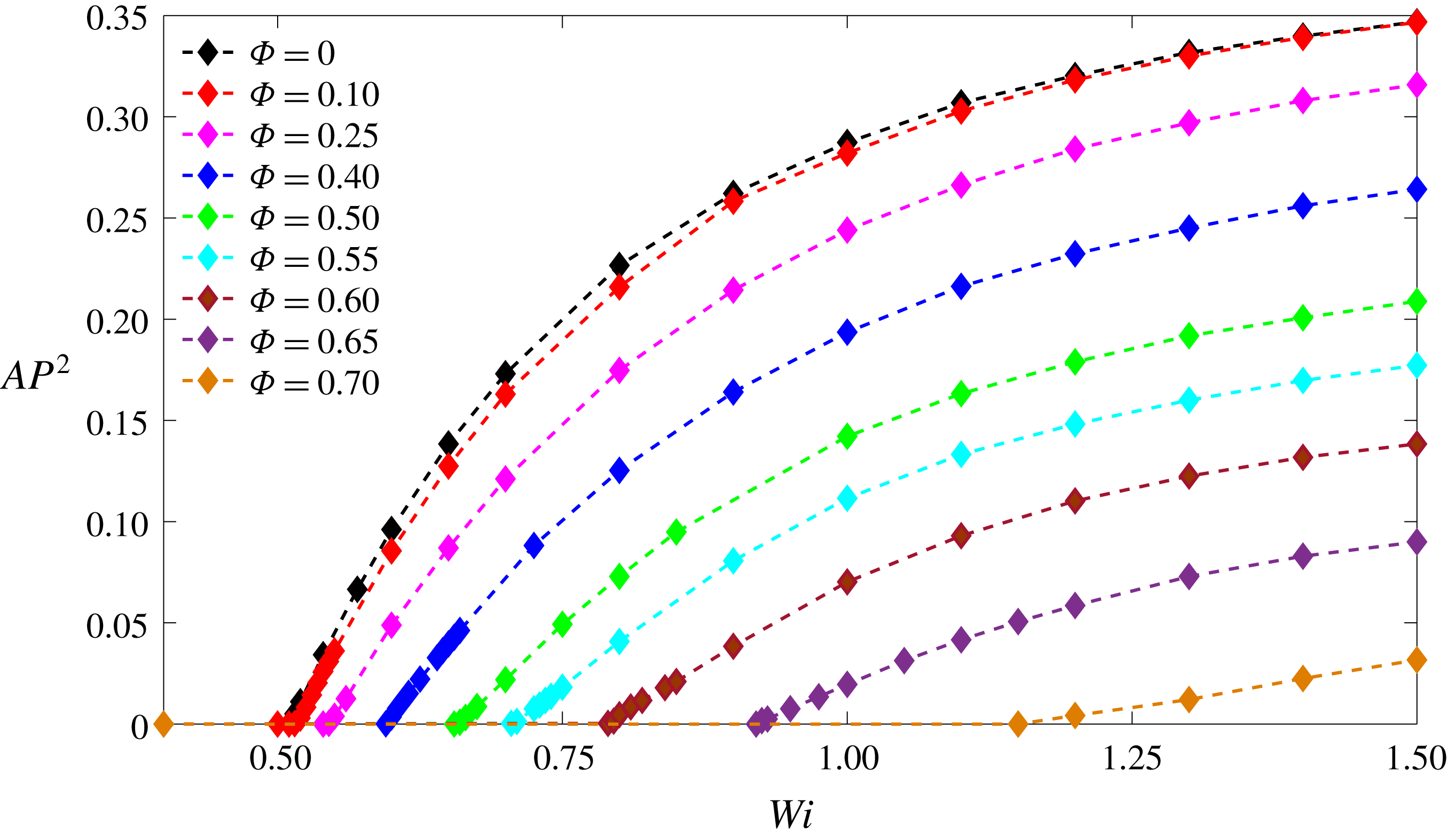
In order to better characterize the magnitude of the observed instability in the numerical simulations, we define an asymmetry parameter as the ratio of the
 $x$
component of velocity to the mean value of velocity in the inlet arms, i.e.
 $AP=(\tilde{U}_{x})/\tilde{U}_{B}$
, at the
 $x=0,y=0.5$
location. Under this definition, if the flow retains its symmetric distribution, the
 $x$
component of velocity at this location will be equal to zero, while once the instability is triggered, due to the asymmetric distribution of the resulting flow,
 $\tilde{U}_{x}$
exhibits a non-zero value.
Effect of Weissenberg number on the symmetry-breaking instability for
 $\unicode[STIX]{x1D6FC}=0.02$
,
 $\unicode[STIX]{x1D6FD}=1/9$
and different blockage ratios
 $\unicode[STIX]{x1D6F7}$
.
Effect of blockage ratio parameter on the symmetry-breaking instability for
 $\unicode[STIX]{x1D6FC}=0.02$
and
 $\unicode[STIX]{x1D6FD}=1/9$
.

Previous studies (Poole et al.
Reference Poole, Alves, Afonso, Pinho and Oliveira2007a
,Reference Poole, Alves and Oliveira
b
) showed that by increasing the Weissenberg number, the symmetry breaking exhibits a supercritical growth close to the bifurcation point. In figure 11, the variation of the asymmetry parameter is plotted versus the Weissenberg number for different values of blockage ratios, which all exhibit a similar supercritical characteristic behaviour for the instability as was observed previously in the standard cross-slot (Poole et al.
Reference Poole, Alves and Oliveira2007b
). In figure 12, we show the effect of the blockage ratio for different constant values of the Weissenberg number with
 $\unicode[STIX]{x1D6FD}=1/9$
and
 $\unicode[STIX]{x1D6FC}=0.02$
. These results show a stabilizing effect of the addition of the cylinder which is characterized by a supercritical behaviour close to the bifurcation point
 $AP^{2}=a(1-\unicode[STIX]{x1D6F7})+b$
, where values of
 $a$
and
 $b$
are shown in figure 12.
Previous experimental studies with the standard cross-slot geometry (Arratia et al.
Reference Arratia, Thomas, Diorio and Gollub2006; Pathak & Hudson Reference Pathak and Hudson2006; Haward et al.
Reference Haward, Ober, Oliveira, Alves and McKinley2012a
; Sousa, Pinho & Alves Reference Sousa, Pinho and Alves2018) have shown that by increasing the Weissenberg number to higher values, one can potentially trigger a second time-dependent instability. A numerical study of shear-thinning sPTT fluids conducted by Cruz et al. (Reference Cruz, Poole, Afonso, Pinho, Oliveira and Alves2016) has also shown that the critical values of Weissenberg number for the onset on instability for both the steady symmetry-breaking and the time-dependent instabilities are a function of the cross-section aspect ratio (
 $AR=\text{height}\text{/}\text{width}$
) and the shear-thinning properties of the fluid (i.e. the
 $\unicode[STIX]{x1D6FC}$
parameter in the sPTT model). In Cruz et al. (Reference Cruz, Poole, Afonso, Pinho, Oliveira and Alves2016), it was shown that once the aspect ratio is sufficiently small, depending on the value of the
 $\unicode[STIX]{x1D6FC}$
parameter, the flow distribution can potentially switch directly from the steady symmetry state to the time-dependent instability. In order to test our hypothesis that a cylinder can delay the steady symmetry-breaking instability, we extend our analysis from 2-D numerical simulations to a series of experiments using the flow-visualization approach introduced in § 3. For this purpose, we use two cross-slot geometries with cross-section aspect ratio of two,
 $AR=2$
, one standard cross-slot geometry and one cross-slot geometry with a cylinder at the geometrical centre with
 $\unicode[STIX]{x1D6F7}=0.55$
. This geometry is selected to best approximate a 2-D channel and observe the steady asymmetry in the standard geometry based on the results of Cruz et al. (Reference Cruz, Poole, Afonso, Pinho, Oliveira and Alves2016).
Visualization of the flow pattern and schematic representation of characteristic lengths used in the definition of the asymmetry parameter in our experiment for the standard cross-slot geometry (
 $\unicode[STIX]{x1D6F7}=0$
) at
 $Re=6\times 10^{-6}$
for solutions of (a) 70 : 30 glycerine–water Newtonian fluid and (b) 190 ppm PAA in 70 : 30 glycerine–water viscoelastic fluid at
 $\bar{Wi}=0.8$
. Fluid with the fluorescent dye is injected from right inlet arm whereas the fluid without dye is injected from left.

A florescent dyed fluid is injected from the right inlet while undyed fluid is pumped in from the left inlet, both at the same flow rate, to visualize the flow distribution in the studied geometries. By increasing the flow rate, we are able to change the Weissenberg number from 0.1 up to 200. Our results suggest that beyond a critical value of the Weissenberg number,
 $\bar{Wi}_{cr}\approx 0.46$
, the symmetry of flow is broken in agreement with previous studies (Arratia et al.
Reference Arratia, Thomas, Diorio and Gollub2006; Sousa et al.
Reference Sousa, Pinho and Alves2018). In the standard cross-slot geometry, figure 13 shows the flow distribution in symmetric Newtonian flows and a steady asymmetric flow for 190 ppm PAA in 70 : 30 glycerine–water viscoelastic fluid at
 $\bar{Wi}=0.8$
and
 $Re=6\times 10^{-6}$
. To better investigate the symmetry-breaking instability we define an experimental asymmetry parameter as
 $AP_{e}=((\tilde{H}11-\tilde{H}12)+(\tilde{H}22-\tilde{H}21))/2\tilde{W}$
. A schematic definition of
 $\tilde{H}11$
,
 $\tilde{H}12$
,
 $\tilde{H}21$
and
 $\tilde{H}22$
is illustrated in figure 13(a).
Variation of the asymmetry parameter against the Weissenberg number for 190 ppm PAA in 70 : 30 glycerine–water viscoelastic fluid in standard cross-slot geometry.

Flow visualization at different instants of the oscillation cycle at the centre of the standard cross-slot geometry at
 $\bar{Wi}=277$
. Fluid with the fluorescent dye is injected from right inlet arm whereas the fluid without dye is injected from left.

Visualization of the flow pattern in cross-slot geometry with
 $\unicode[STIX]{x1D6F7}=0.55$
at
 $Re=2\times 10^{-5}$
for solutions of (a) 70 : 30 glycerine–water Newtonian fluid and (b) 190 ppm PAA in 70 : 30 glycerine–water viscoelastic fluid at
 $\bar{Wi}=2.3$
. Fluid with the fluorescent dye is injected from right inlet arm whereas the fluid without dye is injected from left.

Flow visualization at different instants of the oscillation cycle at the centre of the cross-slot geometry with
 $\unicode[STIX]{x1D6F7}=0.55$
and
 $\bar{Wi}=18.5$
. Fluid with the fluorescent dye is injected from right inlet arm whereas the fluid without dye is injected from left.

In figure 14, we show that the symmetry-breaking instability in the standard cross-slot geometry which, near the bifurcation point, follows a supercritical growth was also observed in our 2-D numerical simulations. As the Weissenberg number is increased to higher values, a time-dependent symmetry-breaking instability develops at
 $\bar{Wi}\approx 92$
which oscillates between two states (see figure 15) with a period of approximately
 $5\bar{\unicode[STIX]{x1D706}}~(\text{s})$
. Unfortunately, our experimental protocol was insufficient to characterize this time dependency more quantitatively.
Following the benchmark of our experimental protocol, we replace the standard cross-slot geometry with a modified geometry with
 $\unicode[STIX]{x1D6F7}=0.55$
. In figure 16, the symmetric distributions of the flow field for both the Newtonian fluid and 190 ppm PAA in 70 : 30 glycerine–water viscoelastic fluid at
 $\bar{Wi}=2.3$
and
 $Re=2\times 10^{-5}$
are presented. Here, unlike the standard cross-slot geometry where the purely elastic symmetry-breaking instability was triggered at
 $\bar{Wi}_{cr}=0.46$
, we were able to retain symmetric flow up to
 $\bar{Wi}_{cr}\approx 3.5$
, qualitatively supporting our numerical simulations regarding the stabilizing effect of the addition of a cylinder.
In the experiments, unlike the prediction from 2-D numerical simulations, we have noticed that by increasing the Weissenberg number to higher values, the flow field switches directly to an unsteady oscillatory instability (figure 17) with no evidence of the steady symmetry-breaking instability. This issue may potentially be related to the effect of finite cross-section aspect ratio in our experiments which was neglected in our 2-D simulations. Having shown experimentally that the cylinder does indeed stabilize the flow field significantly, we return to numerical simulations to probe additional effects and to see if we can quantify how the blockage ratio delays onset.
Figure 18 shows the ‘stability diagram’ for the modified geometry. As can be seen, above the black dashed line (the data are shown by red filled diamonds) are the regions in which the flow exhibits a steady asymmetric distribution. Our simulations suggest that as the size of the cylinder approaches zero, its modifying effects on the symmetry-breaking instability fade away and the critical value of the Weissenberg number for the onset of the instability approaches the same value as in the standard cross-slot geometry. One should note that a combination of conservation of mass (i.e.
 $(\unicode[STIX]{x2202}U_{r}/\unicode[STIX]{x2202}r)+(1/r)(\unicode[STIX]{x2202}U_{\unicode[STIX]{x1D703}}/\unicode[STIX]{x2202}\unicode[STIX]{x1D703})=0$
) with the no-slip boundary condition (i.e. velocity at the cylinder wall is equal to zero and due to the no-slip boundary condition
 $\unicode[STIX]{x2202}U_{\unicode[STIX]{x1D703}}/\unicode[STIX]{x2202}\unicode[STIX]{x1D703}|_{r=\unicode[STIX]{x1D6F7}}=0$
) requires the strain rate at the stagnation point at the cylinder to become zero. So, by replacing the free stagnation point with pinned stagnation points, independent of the cylinder size, a non-zero value of strain rate at the stagnation point is replaced with a zero value once the no-slip boundary condition is applied (as confirmed in figure 19).
By changing the applied boundary condition at the cylinder surface at a constant blockage ratio, we attempt to analyse the onset sensitivity of the purely elastic instability with the magnitude of the strain rate in the vicinity of the cylinder. In figures 19 and 20, the strain rate distribution along the symmetry lines before the onset of instability is plotted using both slip and no-slip boundary conditions at the cylinder surface. The obtained results suggest that by replacing the no-slip boundary condition with the slip boundary condition, although the zero strain rate value at the stagnation point is replaced by a larger non-zero value (approximately 3.5 times larger than the maximum value of strain rate at the standard cross-slot geometry), the critical value of the Weissenberg number for which the instability is triggered stays almost constant at least in the small-aspect-ratio limit (i.e.
 $Wi_{cr}\approx 0.51$
for
 $\unicode[STIX]{x1D6F7}=0.05$
).
Boundary between the symmetric and asymmetric flow for different
 $Wi$
and blockage ratio for
 $\unicode[STIX]{x1D6FC}=0.02$
and
 $\unicode[STIX]{x1D6FD}=1/9$
.

Effect of blockage ratio parameter on the flow strain rate before the start of instability for
 $\unicode[STIX]{x1D6FC}=0.02$
and
 $\unicode[STIX]{x1D6FD}=1/9$
along (a) horizontal line and (b) vertical line. (The critical values of
 $Wi$
for
 $\unicode[STIX]{x1D6F7}=0,0.25,0.40,0.50,0.55,0.60,0.65$
are
 $0.51,0.54,0.59,0.66,0.7,0.78,0.9$
, respectively.)

Effect of slip boundary condition at the cylinder on flow strain rate along (a) horizontal line and (b) vertical line for creeping Newtonian flows and viscoelastic fluids before the start of the purely elastic instability for
 $\unicode[STIX]{x1D6FC}=0.02$
,
 $\unicode[STIX]{x1D6FD}=1/9$
and
 $\unicode[STIX]{x1D6F7}=0.05$
.

Effect of (a) geometry modification and (b) slip boundary condition on the magnitude of the velocity field for creeping Newtonian fluid flows.

As shown in figure 21, the effects of the geometry modification and change of the boundary condition for
 $\unicode[STIX]{x1D6F7}=0.10$
are essentially local and mainly influence the flow distribution near the central region. Our results presented in figures 18–21 show that in the limit where the blockage ratio tends to zero (
 $\unicode[STIX]{x1D6F7}\rightarrow 0$
), even by applying fundamental changes on the kinematic characteristics of the flow field in the vicinity of the stagnation point (changing both the strain rate value and the curvature of streamlines), the critical value of the Weissenberg number for which the instability is triggered tends towards its critical value for the standard cross-slot geometry (i.e.
 $Wi_{cr}=0.51$
). These data strongly suggest the symmetry-breaking instability in the cross-slot geometry is triggered at a location away from the geometric centre and closer to the corner regions as it is essentially independent of the kinematic properties of the flow near the stagnation point.
Illustrative contours of
 $M$
parameter for
 $\unicode[STIX]{x1D6FC}=0.02$
and
 $\unicode[STIX]{x1D6FD}=1/9$
.

Variation of critical values of Weissenberg number against the blockage ratio parameter for
 $\unicode[STIX]{x1D6FC}=0.02$
and
 $\unicode[STIX]{x1D6FD}=1/9$
(analytical fit:
 $1/Wi_{cr}=-1.9578\unicode[STIX]{x1D6F7}^{2}+1.9858$
).

From the results presented we conclude that the high shear rate along with the high streamline curvature near the four cross-slot corners is more likely to be responsible for the transition to an asymmetric flow pattern and we therefore apply the ideas developed by McKinley et al. (Reference McKinley, Pakdel and Öztekin1996) to investigate this possibility. Following the numerical procedure explained by Cruz et al. (Reference Cruz, Poole, Afonso, Pinho, Oliveira and Alves2016), we have plotted the local distribution of the
 $M$
parameter (1.1) in figure 22. Local illustration of the
 $M$
parameter can be an effective way to observe the location of instability-driving regions within the flow field. As expected from previous results, the maximum value of the
 $M$
parameter appears near the corners which is related to the high curvature of streamlines and shear rate in this region (Hinch Reference Hinch1993).
One of the interesting properties of the
 $M$
parameter is related to its ability to scale purely elastic instabilities with respect to both rheological and geometrical properties of the problem (McKinley et al.
Reference McKinley, Pakdel and Öztekin1996; Pakdel & McKinley Reference Pakdel and McKinley1998; Alves & Poole Reference Alves and Poole2007; Zilz et al.
Reference Zilz, Poole, Alves, Bartolo, Levaché and Lindner2012). Here, we use the approach suggested by McKinley et al. (Reference McKinley, Pakdel and Öztekin1996) to model the effect of blockage ratio. An initial analysis suggests that neither
 $\tilde{D}$
nor
 $\tilde{W}$
provides a good approximation of the characteristic curvature of the streamlines in the cross-slot cylinder geometry, and in fact this characteristic length scale is influenced by both of these parameters. In appendix A, using an approximate analytical solution for creeping Newtonian flows, we show that the streamline curvature should scale as
 $$\begin{eqnarray}\displaystyle {\displaystyle \frac{1}{\tilde{\Re }}}={\displaystyle \frac{1}{\tilde{W}}}(a+b\unicode[STIX]{x1D6F7}^{2}), & & \displaystyle\end{eqnarray}$$
where
 $a$
and
 $b$
are undetermined constants. The results presented in figure 22 clearly show that the highest value of the
 $M$
parameter appears in the vicinity of the corner’s shear-dominated regions. Assuming a steady-state purely shear flow for an Oldroyd-B fluid (to which the sPTT model approaches in the
 $\unicode[STIX]{x1D6FC}\rightarrow 0$
limit), one may scale the normal-stress component in (1.1) as
 $$\begin{eqnarray}\displaystyle \tilde{\unicode[STIX]{x1D70F}}_{ss}=2\tilde{\unicode[STIX]{x1D706}}\tilde{\unicode[STIX]{x1D702}}_{p}\tilde{\dot{\unicode[STIX]{x1D6FE}}}^{2}. & & \displaystyle\end{eqnarray}$$
Using
 $\tilde{U}_{b}$
and
 $\tilde{\Re }$
as references for the velocity field and the length scale, the reference shear rate may be expressed as
 $\tilde{\dot{\unicode[STIX]{x1D6FE}}}=\tilde{U}_{b}/\tilde{\Re }$
. Substitution of these equations into the dimensionless
 $M$
criteria (1.1) results in the following condition for the onset criteria of purely elastic instability in the modified cross-slot geometry:
 $$\begin{eqnarray}\displaystyle M_{c}=\sqrt{{\displaystyle \frac{\tilde{\unicode[STIX]{x1D706}}\tilde{U}_{b}}{\tilde{W}}}(a+b\unicode[STIX]{x1D6F7}^{2})2(1-\unicode[STIX]{x1D6FD}){\displaystyle \frac{\tilde{\unicode[STIX]{x1D706}}\tilde{U}_{b}}{\tilde{W}}}(a+b\unicode[STIX]{x1D6F7}^{2})}, & & \displaystyle\end{eqnarray}$$
where
 $a$
,
 $b$
and
 $M_{c}$
are unknown constants. However, factoring out the quantity
 $(\tilde{\unicode[STIX]{x1D706}}\tilde{U}_{b}/\tilde{W})^{2}$
and with some rearrangement one can simplify the equation into
 $$\begin{eqnarray}\displaystyle {\displaystyle \frac{1}{Wi_{cr}}}=\bar{a}+\bar{b}\unicode[STIX]{x1D6F7}^{2}, & & \displaystyle\end{eqnarray}$$
where
 $\bar{a}=a\sqrt{2(1-\unicode[STIX]{x1D6FD})}/M_{c}$
and
 $\bar{b}=b\sqrt{2(1-\unicode[STIX]{x1D6FD})}/M_{c}$
are now the unknown constants. Figure 23 shows the fit obtained based on (4.5) and our 2-D numerical simulations. From this prediction (4.5), one can show
 $\unicode[STIX]{x2202}Wi_{cr}/\unicode[STIX]{x2202}\unicode[STIX]{x1D6F7}=0$
once
 $\unicode[STIX]{x1D6F7}\rightarrow 0$
, suggesting that, in the limit
 $\unicode[STIX]{x1D6F7}\rightarrow 0$
, the modifying effect of the addition of a cylinder on the critical kinematic properties of the flow field and the onset criteria of instability fades away (figure 18 also illustrates this point). Bearing in mind that (4.5) is obtained using a pure-shear flow assumption (i.e. (4.3)) and scaling of streamline curvature is obtained using a Taylor expansion in the vicinity of corners, the surprisingly good agreement between the analytical prediction (4.5) and numerical simulations once again suggests that the instability is triggered due to the shear flow near the corners and not the elongational-dominated flow at the stagnation point itself. Finally, to test the sensitivity of our chosen model parameters, in appendix B we show how the extensibility parameter in the sPTT model modifies the critical conditions and in appendix C we show that the same results can be observed with the FENE-P model in certain parameter limits.
5 Conclusions
In this work a passive control mechanism is introduced to the cross-slot geometry by the addition of a cylinder at the geometric centre of the domain. We use a series of numerical simulations and an approximate analytical analysis, using the definition of the
 $M$
parameter introduced by McKinley et al. (Reference McKinley, Pakdel and Öztekin1996), to scale and analyse the stabilizing effect of the proposed geometrical modification on the onset criteria for a purely elastic instability and compare these results to our experimental data. Our work suggests that, in the limit
 $\unicode[STIX]{x1D6F7}\rightarrow 0$
, replacing the finite strain rate ‘free’ stagnation point flow with zero strain rate ‘pinned’ stagnation points at the cylinder surface does not affect the onset for the purely elastic instability. We extend our simulations by applying a complete slip boundary condition at the cylinder thereby changing the maximum strain rate from zero to approximately 3.5 times the strain rate in the standard cross-slot geometry, to show that the kinematic properties of the flow distribution around the stagnation point do not play any significant role in the onset of the purely elastic symmetry-breaking instability and that the critical values of the Weissenberg number for which the instability is triggered, in both cases, tend toward the critical value for the standard cross-slot geometry (i.e.
 $Wi\approx 0.51$
). Finally, by plotting the local distribution of the
 $M$
parameter, we show that the location of instability-driving regions appears in the vicinity of the corners which can be attributed to the high deformation rate and strong streamline curvature in this region. We also show how the effect of blockage ratio scales with the onset criteria and thus can be successfully used to predict onset conditions.
Acknowledgements
The authors would like to sincerely thank Dr D. J. C. Dennis (University of Liverpool, UK) for his valuable help during this project. R.J.P. gratefully acknowledges funding from the EPSRC (UK) through grant no. EP/M025187/1.
Appendix A. Analytical approach for determining the
 $M_{cr}$
parameter

In this appendix, an approximate analytical solution for the flow distribution of a creeping Newtonian fluid along a diagonal line between a corner and a stagnation point is obtained (a schematic of the problem is depicted in figure 1). Moving to a cylindrical coordinate system, the components of the velocity vector in terms of the stream function are
 $$\begin{eqnarray}\displaystyle & \displaystyle \tilde{U_{\unicode[STIX]{x1D703}}}=\frac{\unicode[STIX]{x2202}\tilde{\unicode[STIX]{x1D713}}}{\unicode[STIX]{x2202}\tilde{r}},\quad \tilde{U_{r}}=-\frac{1}{\tilde{r}}\frac{\unicode[STIX]{x2202}\tilde{\unicode[STIX]{x1D713}}}{\unicode[STIX]{x2202}\unicode[STIX]{x1D703}}. & \displaystyle\end{eqnarray}$$
For steady Newtonian flows, the conservation of momentum equation using the definition of stream function may be presented as
 $$\begin{eqnarray}\displaystyle \unicode[STIX]{x1D6FB}^{4}\tilde{\unicode[STIX]{x1D713}}=0. & & \displaystyle\end{eqnarray}$$
Separation of the stream function into a function of a radial line
 $f(\tilde{r})$
and a function of the polar angle which is periodic with the wavenumber
 $m$
allows us to obtain the general form of the analytical solution for (A 2) as
 $$\begin{eqnarray}\displaystyle \tilde{\unicode[STIX]{x1D713}}=(C_{1}\tilde{r}^{m}+C_{2}\tilde{r}^{-m}+C_{3}\tilde{r}^{m+2}+C_{4}\tilde{r}^{m-2})\text{e}^{\text{i}m\unicode[STIX]{x1D703}}. & & \displaystyle\end{eqnarray}$$
The analytical solution obtained by Moffatt (Reference Moffatt1964) for the creeping flow of Newtonian fluids around a sharp corner implies that the stream function must have the following form:
 $$\begin{eqnarray}\displaystyle \tilde{\unicode[STIX]{x1D713}}=A\tilde{r}^{1.5445}(\cos (0.3415\unicode[STIX]{x03C0})\cos (1.5445\unicode[STIX]{x1D703})-\cos (1.158\unicode[STIX]{x03C0})\cos (0.4555\unicode[STIX]{x1D703})). & & \displaystyle\end{eqnarray}$$
Using the general form of the stream function solution (A 3), we aim to find an approximate analytical expression for the stream function which as
 $r\rightarrow 0$
the solution asymptotes to the exact solution presented by Moffatt (Reference Moffatt1964) (i.e. equation (A 4)). One should note that
 $1<m<3$
, which implies that the velocity is not singular at
 $\tilde{r}=0$
and the velocity gradient has a bounded value far from the corner. Equation (A 4) shows that as
 $\tilde{r}\rightarrow 0$
the stream function must have wavenumbers (the
 $m$
parameter in (A 3)) of 0.4555 and 1.5445.
Using the suggested values for
 $m$
in (A 3), the stream function is now
 $$\begin{eqnarray}\displaystyle \tilde{\unicode[STIX]{x1D713}} & = & \displaystyle A\tilde{r}^{1.5445}(\cos (0.3415\unicode[STIX]{x03C0})\cos (1.5445\unicode[STIX]{x1D703})-\cos (1.158\unicode[STIX]{x03C0})\cos (0.4555\unicode[STIX]{x1D703}))\nonumber\\ \displaystyle & & \displaystyle +\,B\tilde{r}^{2.4555}\cos (0.4555\unicode[STIX]{x1D703}).\end{eqnarray}$$
Considering the following constraints at
 $\unicode[STIX]{x1D703}=0$
:
 $$\begin{eqnarray}\displaystyle & \displaystyle \tilde{U_{\unicode[STIX]{x1D703}}}\mid _{\tilde{r}=\tilde{L}}=0, & \displaystyle\end{eqnarray}$$
 $$\begin{eqnarray}\displaystyle & \displaystyle \int _{0}^{\tilde{L}}\tilde{U_{\unicode[STIX]{x1D703}}}\,\text{d}\tilde{r}={\textstyle \frac{1}{2}}\tilde{U_{B}}\tilde{W}, & \displaystyle\end{eqnarray}$$
the unknown constants can then be calculated as
 $$\begin{eqnarray}\displaystyle A={\displaystyle \frac{0.9938\tilde{W}\tilde{U}_{B}}{\tilde{L}^{1.5445}}},\quad B={\displaystyle \frac{-0.8477\tilde{W}\tilde{U}_{B}}{\tilde{L}^{2.4555}}}. & & \displaystyle\end{eqnarray}$$
Using (A 1), one can then calculate the components of the velocity vector along the line
 $\unicode[STIX]{x1D703}=0$
with
 $\tilde{L}=\sqrt{2}/2\tilde{W}$
as
 $$\begin{eqnarray}\displaystyle \tilde{U_{\unicode[STIX]{x1D703}}}=3.5551\tilde{U}_{B}\left({\displaystyle \frac{\tilde{r}}{\tilde{W}}}\right)^{0.5445}-4.8749\tilde{U}_{B}\left({\displaystyle \frac{\tilde{r}}{\tilde{W}}}\right)^{1.4555},\quad \tilde{U_{r}}=0. & & \displaystyle\end{eqnarray}$$
A comparison between this approximate analytical solution and the numerical result is shown in figure 24 where a good agreement can be observed. Knowing the functional form of the velocity (A 5), the curvature of the streamline may be calculated as (Cruz et al. Reference Cruz, Poole, Afonso, Pinho, Oliveira and Alves2016; Haward et al. Reference Haward, McKinley and Shen2016)
 $$\begin{eqnarray}\displaystyle \tilde{\Re }=(|\tilde{\boldsymbol{u}}|)^{3}/\left(\left|\tilde{\boldsymbol{u}}\times {\displaystyle \frac{\text{D}\tilde{\boldsymbol{u}}}{\text{D}\tilde{t}}}\right|\right), & & \displaystyle\end{eqnarray}$$
where
 $\text{D}\tilde{\boldsymbol{u}}/\text{D}\tilde{t}$
is the material derivative of the velocity vector. Using the definition of the stream function, one can calculate
 $1/\tilde{\Re }$
as follows:
 $$\begin{eqnarray}\displaystyle {\displaystyle \frac{1}{\tilde{\Re }}}={\displaystyle \frac{1.538(\tilde{L})^{0.911}-3.811\tilde{r}^{0.911}}{(4.163(\tilde{L})^{0.911}-4.163\tilde{r}^{0.911})\tilde{r}}}. & & \displaystyle\end{eqnarray}$$
One should notice that the present analytical solution is only an approximate solution for creeping Newtonian fluid flow between the corner of the cross-slot geometry and the stagnation point and so the obtained stream function does not satisfy the boundary conditions at the walls and does not present a correct
 $\unicode[STIX]{x1D703}$
dependency away from
 $\unicode[STIX]{x1D703}=0$
.
Velocity distribution along the radial direction at
 $\unicode[STIX]{x1D703}=0$
for both the analytical and numerical simulations for standard cross-slot geometry, Newtonian fluid and
 $Re=0.01$
.

To include the effect of the cylinder at the centre of the cross-slot geometry, we consider the diagonal gap length
 $\tilde{L}$
to be simply
 $$\begin{eqnarray}\displaystyle \tilde{L}={\displaystyle \frac{\sqrt{2}}{2}}\tilde{W}-{\displaystyle \frac{\tilde{D}}{2}}. & & \displaystyle\end{eqnarray}$$
Using (A 12) and some simplification with a Taylor expansion around the corner of the cross-slot geometry, the
 $1/\tilde{\Re }$
term can be expressed as
 $$\begin{eqnarray}\displaystyle {\displaystyle \frac{1}{\tilde{\Re }}} & = & \displaystyle {\displaystyle \frac{0.369}{\tilde{W}\left({\displaystyle \frac{\tilde{r}}{\tilde{W}}}\right)}}\biggl(1-3.388\left({\displaystyle \frac{\tilde{r}}{\tilde{W}}}\right)^{0.911}(1+0.642\unicode[STIX]{x1D6F7})\biggr)\nonumber\\ \displaystyle & & \displaystyle \times \biggl(1+1.366\left({\displaystyle \frac{\tilde{r}}{\tilde{W}}}\right)^{0.911}(1+0.642\unicode[STIX]{x1D6F7})\biggr).\end{eqnarray}$$
Equation (A 13) suggests a second-order dependency of the streamline curvature with the blockage ratio parameter. Here we assume that, prior to instability, viscoelasticity does not significantly affect the scaling correlation between the streamline curvature and the blockage ratio and we will proceed to scale the
 $M$
parameter with the blockage ratio parameter based on (A 13). In the end we will check the accuracy of this hypothesis by plotting the obtained approximate analytical expression with our numerical results.
For an Oldroyd-B fluid, assuming steady-state simple shear, the second term on the right-hand side of (1.1) can be simplified to
 $$\begin{eqnarray}\displaystyle {\displaystyle \frac{\tilde{\unicode[STIX]{x1D70F}}_{11}}{\tilde{\unicode[STIX]{x1D702}_{0}}\tilde{\dot{\unicode[STIX]{x1D6FE}}}}}=2(1-\unicode[STIX]{x1D6FD})\tilde{\unicode[STIX]{x1D706}}\tilde{\dot{\unicode[STIX]{x1D6FE}}}. & & \displaystyle\end{eqnarray}$$
Considering
 $\tilde{U}_{B}$
as our reference velocity, and using the derived
 $\tilde{\Re }$
parameter as our reference length (i.e. equation (4.2)), after some simplifications, one can state
 $$\begin{eqnarray}\displaystyle {\displaystyle \frac{1}{Wi_{c}}}={\displaystyle \frac{a\sqrt{2(1-\unicode[STIX]{x1D6FD})}}{M_{c}}}+\unicode[STIX]{x1D6F7}^{2}{\displaystyle \frac{b\sqrt{2(1-\unicode[STIX]{x1D6FD})}}{M_{c}}}\equiv a^{\ast }+b^{\ast }\unicode[STIX]{x1D6F7}^{2}, & & \displaystyle\end{eqnarray}$$
so that a plot of the reciprocal of the critical condition
 $(1/Wi_{c})$
against
 $\unicode[STIX]{x1D6F7}^{2}$
should be linear with intercept
 $a^{\ast }$
and slope
 $b^{\ast }$
(figure 23 shows this plot confirming the approximate analysis).
Appendix B. Effect of extensibility parameter in sPTT model
In this appendix, the effect of the extensibility parameter
 $\unicode[STIX]{x1D6FC}$
of the sPTT model on the purely elastic symmetry-breaking instability is investigated. In the limiting case where
 $\unicode[STIX]{x1D6FC}\rightarrow 0$
the sPTT model reduces to the Oldroyd-B model which predicts a constant viscosity for the viscoelastic materials and the elastic stress in a pure shear flow can be scaled as
 $2\tilde{\unicode[STIX]{x1D706}}\tilde{\unicode[STIX]{x1D702}}_{p}\tilde{\dot{\unicode[STIX]{x1D6FE}}}^{2}$
. In the sPTT model, for a non-zero value of
 $\unicode[STIX]{x1D6FC}$
, due to shear-thinning properties of viscosity, the magnitude of first normal-stress difference reduces and scales as
 $2\tilde{\unicode[STIX]{x1D706}}\tilde{\unicode[STIX]{x1D702}}_{p}\tilde{\dot{\unicode[STIX]{x1D6FE}}}^{n}$
, where
 $n<2$
. This suggests that the local value of the Weissenberg number (the ratio of elastic to viscous stress) reduces as the
 $\unicode[STIX]{x1D6FC}$
parameter increases once the flow is subject to a constant shear rate. In figure 25 the variation of the asymmetry parameter versus
 $Wi$
for different values of
 $\unicode[STIX]{x1D6FC}$
is plotted, showing a supercritical growth near the bifurcation point. As shown, on increasing the extensibility parameter the critical value of the Weissenberg number for the onset of symmetry-breaking instability is delayed to higher values which may be a consequence of the shear-thinning of the first normal-stress difference. In figure 26, the variation of the critical Weissenberg number
 $Wi_{cr}$
with the
 $\unicode[STIX]{x1D6FC}$
parameter is shown.
Effect of extensibility parameter on symmetry-breaking instability of flow for
 $\unicode[STIX]{x1D6F7}=0.50$
and
 $\unicode[STIX]{x1D6FD}=1/9$
.

Effect of extensibility parameter on critical Weissenberg number for
 $\unicode[STIX]{x1D6F7}=0.50$
and
 $\unicode[STIX]{x1D6FD}=1/9$
.

Comparison of rheological properties for (a) planar elongational viscosity and (b) shear viscosity and the first normal stress between sPTT (
 $\unicode[STIX]{x1D6FC}=2\times 10^{-4}$
) and FENE-P (
 $L^{2}=5000$
) models with
 $\unicode[STIX]{x1D6FD}=1/9$
, in standard pure shear and planar elongational flows.

Variation of asymmetry parameter with the Weissenberg number for sPTT (
 $\unicode[STIX]{x1D6FC}=2\times 10^{-4}$
) and FENE-P (
 $L^{2}=5000$
) models with
 $\unicode[STIX]{x1D6FD}=1/9$
in a standard cross-slot geometry.

Appendix C. Two-dimensional simulations using the FENE-P model
In this appendix, we use the FENE-P model as a second constitutive equation to match the rheological properties of our model with the sPTT constitutive equation and show that the same effect is observed regardless of constitutive equation. Expanding the upper-convective derivative in (2.6), the FENE-P model can be rewritten as
 $$\begin{eqnarray}\displaystyle \tilde{\unicode[STIX]{x1D70F}}+\tilde{\unicode[STIX]{x1D706}}\left(\left(\stackrel{\unicode[STIX]{x1D735}}{\tilde{\unicode[STIX]{x1D749}}}{\displaystyle \frac{1}{f_{2}}}\right)+\tilde{\unicode[STIX]{x1D749}}\stackrel{\unicode[STIX]{x1D735}}{\left({\displaystyle \frac{1}{f_{2}}}\right)}\right)={\displaystyle \frac{a\tilde{\unicode[STIX]{x1D702}}_{p}}{f_{2}}}(\unicode[STIX]{x1D735}\tilde{\boldsymbol{u}}+\unicode[STIX]{x1D735}\tilde{\boldsymbol{u}}^{\text{T}})-a\tilde{\unicode[STIX]{x1D702}}_{p}\left({\displaystyle \frac{\text{D}}{\text{D}\tilde{t}}}\left({\displaystyle \frac{1}{f_{2}}}\right)\right)\boldsymbol{I}. & & \displaystyle\end{eqnarray}$$
In ideal steady-state shear/extensional flows, the term
 $(\stackrel{\unicode[STIX]{x1D735}}{1}/f_{2})$
is equal to zero and in the limit where
 $L^{2}$
finds a large value (
 $a\rightarrow 1$
), the FENE-P model reduces to (Oliveira Reference Oliveira2009)
 $$\begin{eqnarray}\displaystyle \left(1+{\displaystyle \frac{\tilde{\unicode[STIX]{x1D706}}(Tr(\tilde{\unicode[STIX]{x1D749}}))}{\tilde{\unicode[STIX]{x1D702}}_{p}L^{2}}}\right)\tilde{\unicode[STIX]{x1D749}}+\tilde{\unicode[STIX]{x1D706}}\stackrel{\unicode[STIX]{x1D735}}{\tilde{\unicode[STIX]{x1D749}}}=\tilde{\unicode[STIX]{x1D702}_{p}}(\unicode[STIX]{x1D735}\tilde{\boldsymbol{u}}+\unicode[STIX]{x1D735}\tilde{\boldsymbol{u}}^{\text{T}}). & & \displaystyle\end{eqnarray}$$
This way of expressing the FENE-P model suggests that in ‘viscometric’ flows, assuming
 $L^{2}\gg 1$
, both the FENE-P and sPTT models are identical when
 $\unicode[STIX]{x1D6FC}=1/L^{2}$
(cf. equation (C 2) and equations (2.3) and (2.5)). In figure 27, this point is illustrated by plotting viscometric functions of both the sPTT and FENE-P models with
 $\unicode[STIX]{x1D6FC}=2\times 10^{-4}$
and
 $L^{2}=5000$
, respectively, with
 $\unicode[STIX]{x1D6FD}=1/9$
. Our simulations with
 $L^{2}=5000$
and
 $\unicode[STIX]{x1D6FC}=2\times 10^{-4}$
shown in figure 28 suggest that once the viscometric functions are matched the instability is triggered at almost the same critical value of the Weissenberg number which may, at first glance, suggest that the critical condition in which the instability is triggered is related to the steady-state viscometric properties of the model. However, one should note that very large values of
 $L^{2}$
in the FENE-P model and very small values of
 $\unicode[STIX]{x1D6FC}$
in the sPTT model may potentially conceal the difference between these two models since in the limit
 $L^{2}\rightarrow \infty$
or
 $\unicode[STIX]{x1D6FC}\rightarrow 0$
both the FENE-P and sPTT models will reduce to the Oldroyd-B model (Bird et al.
Reference Bird, Armstrong and Hassager1987).
Comparison of rheological properties for (a) planar elongational viscosity and (b) shear viscosity and the first normal stress between sPTT (
 $\unicode[STIX]{x1D6FC}=0.02$
) and FENE-P (
 $L^{2}=58$
) models with
 $\unicode[STIX]{x1D6FD}=0.2$
, in standard pure shear and planar elongational flows.

Variation of asymmetry parameter with the Weissenberg number for sPTT (
 $\unicode[STIX]{x1D6FC}=0.02$
) and FENE-P (
 $L^{2}=58$
) models with
 $\unicode[STIX]{x1D6FD}=0.2$
in a standard cross-slot geometry.

In another attempt, to better investigate the effect of rheological properties of the fluids, we try to fit the viscometric functions using a smaller value of
 $L^{2}$
and a larger value of the
 $\unicode[STIX]{x1D6FC}$
parameter in these two models. Figure 29 shows the fit obtained between viscometric function of sPTT model with
 $\unicode[STIX]{x1D6FC}=0.02$
and FENE-P model with
 $L^{2}=58$
at a fixed value of
 $\unicode[STIX]{x1D6FD}=0.2$
. Interestingly, as shown in figure 30, although the steady-state viscometric functions between the two constitutive equations are in good agreement, the critical values of the Weissenberg number for the onset of the instability are significantly different in these two models. This result provides further evidence that the kinematic properties of the flow triggering the instability are, most probably, related to the non-homogeneous aspects of this complex flow and not solely related to the stagnation point.


 Open access

