Introduction
The Federal Communications Commission authorized the commercial use of the ultrawideband (UWB) frequency band from 3.1 to 10.6 GHz in 2002 [1]. However, other narrowband wireless systems operate in this frequency band, such as 5G (3.3–4.4 GHz)/WiMAX (3.3–3.6 GHz), WLAN (5.15–5.825 GHz), and X-band (7.25–7.75 GHz) bands, which cause electromagnetic interference with UWB systems. To avoid this, designing antennas with notch bands is necessary.
A variety of band notch techniques has been investigated, including etching slots in the radiating patch [Reference Hammache, Messai, Messaoudene and Denidni2–Reference Elhabchi, Srifi and Touahni4], in the ground plane [Reference Ramin and Javad5, Reference Lakrit, Das and El Alami6], or in the feedline [Reference Mahdi and Abazari7, Reference Sarkar, Srivastava and Saurav8], inserting strips into the radiating patch [Reference Srinivas and Ashwin9–Reference Nasrabadi and Rezaei11], and utilizing split-ring resonators (SRRs) coupled to the feedline [Reference Siddiqui, Saha and Antar12]. Although the techniques can generate notch bands and suppress interference, the notch bands are fixed, and the UWB spectrum cannot be utilized efficiently when the interference is removed.
To achieve better spectrum utilization, reconfigurable band notch antennas have been proposed. Electrical switches, such as varactors, radio-frequency microelectromechanical systems (RF-MEMS), and p-type intrinsic n-type (PIN) diodes, are used to realize reconfigurability. Varactors are used for continuous frequency tuning in a moderate range [Reference Tang, Wang, Deng and Ziolkowski13, Reference Karami, Zahra and Jordi14], and RF-MEMS [Reference Nikolaou, Kingsley, Ponchak, Papapolymerou and Tentzeris15, Reference Horestani, Shaterian, Naqui, Martín and Fumeaux16] are implemented by a special process. Thus, PIN diodes are better options for microstrip patch antennas switching the notch bands on/off in a large frequency range.
PIN diode-based reconfigurable antennas are presented in [Reference Sajjad, Yasser and Nasser17–Reference Manish, Kumar and Himanshu23]. In [Reference Sajjad, Yasser and Nasser17], a PIN diode is used to connect the triangular-shaped slot in the radiator, and hence, the antenna can generate a single switchable notch band at WLAN with a size of 20 × 20 mm2. In [Reference Abdurrahim and Mehmet18], a PIN diode is inserted between the poles of the G-shaped radiator to achieve a single reconfigurable notch band covering C-band and WiMAX, and the size of the antenna is 8 × 27.5 mm2. However, just a single switchable notch band is insufficient to reject the common interference in the frequency range. A reconfigurable dual band notch antenna is presented in [Reference Gunjan, Santanu and Kumar19], which incorporates a PIN diode between two T-shaped strips and a pair of PIN diodes on an elliptical SRR. The antenna can suppress the interfering bands of WiMAX and WLAN, with a size of 27 × 32 mm2. In [Reference Yingsong, Wenxing and Qiubo20], reconfigurable dual band notch functions blocking WLAN and X-band are obtained by using two diodes on the subs. The antenna has a size of 24 × 32 mm2.
In both [Reference Yingsong, Wenxing and Qiubo21, Reference Shrivishal, Akhilesh and Sandeep22], reconfigurable dual band notch antennas with triple band notch characteristics are realized. In [Reference Yingsong, Wenxing and Qiubo21], notch bands at WiMAX and WLAN can be independently controlled by switching four diodes on two T-shaped strips and two parallel stubs, with an antenna size of 24 × 32 mm2, whereas in [Reference Shrivishal, Akhilesh and Sandeep22], dual band notch reconfigurability at the WiMAX and X-bands is achieved by switching two diodes on two C-shaped slots, with an antenna size of 24.5 × 20 mm2. A reconfigurable triple band notch antenna with a size of 20 × 22 mm2 is proposed in [Reference Manish, Kumar and Himanshu23], which can switch WiMAX, WLAN, and X-band on/off by modifying the structure of the radiator. However, this antenna does not have dual band notch functions; therefore, it can neither suppress the interference nor utilize the spectrum efficiently when any two of the interfering bands simultaneously exist. None of the presented designs can reject all the common interfering bands, including WiMAX, WLAN, and X-band, with independent switch ability. Furthermore, due to the reconfigurable structures, the sizes of the discussed multi-band notch antennas are always large.
In this paper, a reconfigurable triple band notch UWB antenna with a compact size is presented. The reconfigurable structure consists of two C-shaped slots in the radiator and a pair of SRRs on the backside, which are controlled by four PIN diodes. All the notch bands at WiMAX, WLAN, and X-band are independently switched on/off; hence, the antenna has multiple operation modes, which can realize single, dual, and triple band notch states in the case of different interference scenarios. Moreover, by etching a nested structure of C-shaped slots and placing a pair of SRRs on the backside, an efficient top-cut circular-shaped radiating patch is designed, which realizes a compact size of 18 × 19.5 mm2. The design details of the prototype antenna are described in the following sections. To prove the performance, the reflection coefficient, radiation patterns, and gain response are simulated and measured.
Antenna design
Configuration of the proposed antenna
Figure 1 depicts the geometry of the proposed antenna, which is fabricated on an 18 × 19.5 mm2 Rogers RT/duroid 5880 substrate with a permittivity of 2.2, a loss tangent of 0.0009, and a thickness of 1.6 mm. The top-cut circular radiator is fed by a 50 Ω coplanar waveguide feedline. The ground plane is beveled, and two notches are cut at the upper corners to extend the bandwidth. Then, two C-shaped slots and a pair of SRRs are utilized to obtain reconfigurable characteristics. The optimized parameters and electrical length of the proposed antenna are listed in Table 1.
Geometry of the proposed UWB antenna: (a) top view and (b) back view.

Optimized parameters of the proposed antenna

To reduce the area of the radiating patch, the C-shaped slots have a nested structure, and the SRRs are placed on the backside. With the help of this layout, a top-cut circular-shaped radiating patch is designed, which is more compact than the circular patch. The radius (R) of the radiating patch is optimized for size miniaturization. Figure 2 presents the reflection coefficient (S 11) of the proposed antenna with R = 6, 6.6, 7, and 8 mm. S 11 across the frequency band from 5.7 to 7.7 GHz increases as R decreases. When R is greater than 6 mm, S 11 is always below −10 dB. To satisfy UWB bandwidth requirements and maintain the margin for measurement, R = 6.6 mm is selected.
Simulated reflection coefficients (S 11) for various radii (R) of the radiating patch.

Band notch characteristics
To reject the 5G/WiMAX band and WLAN band, two C-shaped slots are inserted into the radiating patch, as shown in Fig. 1. The C-shaped slots resonate at the center frequencies of the interfering bands with resonant lengths of 31.2 and 20.8 mm. The relation between the resonant frequency and length is expressed by the following formulas:


where f is the resonant frequency, Lslot is the inner perimeter of a slot, c is the speed of light, ɛreff is the effective dielectric constant, and ɛr is the relative dielectric constant.
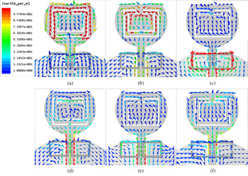
At resonance, the currents flowing around the slots become densest and are directed oppositely at the interior and exterior edges, as shown in Figs 3(a) and 3(b). Therefore, the resultant radiation fields cancel out, and the notch band can be generated.
Simulated current distributions of the antenna without PIN diodes at (a) 3.8 GHz, (b) 5.7 GHz, and (c) 7.7 GHz. Simulated current distributions of the antenna for mode 3 (d), mode 2 (e), and mode 4 (f) in Table 2.

According to the analysis in [Reference Baena, Bonache and Martín24], SRRs excited by a time-harmonic magnetic field behave as an LC resonator. Therefore, to suppress X-band interference, a pair of SRRs is printed on the backside of the antenna, as shown in Fig. 1. The SRRs, symmetrical with respect to the longitudinal direction, have one resonant frequency due to the identical size of the two rings and mutual coupling between them. When the SRRs are resonant at the center frequency of X-band, the surface current concentrated on the two rings does not radiate through the radiating patch, as illustrated in Fig. 3(c), which results in the notch band.
Reconfigurable characteristics
Four PIN diodes (SMP1320-079) are introduced to acquire reconfigurable characteristics. As shown in Fig. 1, two PIN diodes (D1 and D2) are placed across the two C-shaped slots. When D1 or D2 is in the OFF state, due to the high isolation of the PIN diode, the current does not pass through them. Therefore, the current distribution is identical to the aforementioned one in Figs 3(a) and 3(b), and the resultant notch bands exist. When D1 or D2 is in the ON state, the surface current passes through it, modifying the current distribution. Figures 3(d) and 3(e) show that the current density decreases and the current flows along the interior and exterior edges are in phase, in contrast to the current distributions in Figs 3(a) and 3(b). This means that at the 5G/WiMAX band or WLAN band, the radiation fields do not cancel out, and therefore, the corresponding notch bands are not generated.
Before placing PIN diodes D3 and D4, two gaps are inserted into the edges opposite to the existing gaps in the SRRs symmetrical to them, as shown in Fig. 1. Then, D3 and D4 are mounted across the new gaps. When D3 and D4 are in the ON state, the gaps are shorted, and the current distribution is similar to that of the original SRRs in Fig. 3(c), resulting in the notch band. In contrast, when D3 and D4 are in the OFF state, the high isolation of the PIN diode leads to an open circuit at the ends of the gaps, and each ring of the SRRs is separated into two U-shaped strips. The current distributions of the separated strips are shown in Fig. 3(f). Compared to the results of the original SRRs, the current concentration disappears, which indicates that the SRRs do not resonate at the center frequency of X-band. Consequently, the corresponding notch band does not exist.
According to the above analysis, the three notch bands can be independently controlled by changing the state of the PIN diodes. Thus, in the case of different interference scenarios, different notch bands are selected, which determine the operation modes of the antenna. The proposed antenna operates in eight modes in the case of common interference scenarios. The details of the multimode reconfigurable band notch function, such as the diode state, measured bandwidth of the notch bands, and center frequency, are described in Table 2.
Different operation modes of the proposed antenna

Fabrication and measurement results
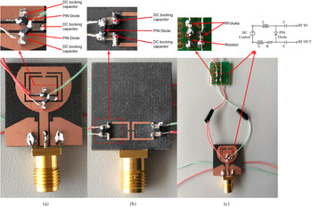
An antenna prototype is fabricated to validate the proposed characteristics, and the PIN diode is biased by a 27 kΩ current-limiting resistor, two 200 nH RF chokes, and seven 10 pF DC-blocking capacitors for measurement, as shown in Fig. 4. To verify the multimode reconfigurable characteristics, the voltage standing wave ratios (VSWRs) for the different modes in Table 2 are simulated by using HFSS and measured by using an Agilent E5063A vector network analyzer. In the simulation process, the lumped RLC components in HFSS are used to simulate the equivalent circuit models of the PIN diodes, as shown in Fig. 5, where Ls = 0.7 nH, Rs = 0.75 Ω, CT = 0.2 pF, and Rp = 10 kΩ.
Photograph of the proposed antenna: (a) top view, (b) back view, and (c) bias circuit.

(a) Equivalent circuit models of PIN diodes in ON/OFF and (b) the lumped RLC components in HFSS.

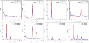
The simulated and experimental VSWR results are presented in Fig. 6. The simulated and experimental results are in acceptable agreement. The slight discrepancies can be attributed to the fabrication process, SMA connector losses, PIN diode model, and measurement environment.
VSWRs of the antenna for the different modes in Table 2.

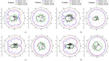
The simulated and experimental radiation patterns in the E-plane and H-plane at 5, 6.5, 8.5, and 10 GHz are exhibited in Fig. 7. As observed, the radiation patterns are nearly bidirectional in the E-plane and almost omnidirectional in the H-plane at all frequency points. Based on a comparison between the cross-polarization and co-polarization depicted in Fig. 7, the cross-polarized values are approximately 20 dB lower than the co-polarized values.
Simulated and measured radiation patterns in the E-plane and H-plane at (a) 5 GHz, (b) 6.5 GHz, (c) 8.5 GHz, and (d) 10 GHz.

The simulated and experimental peak gains for mode 8 in Table 2 are shown in Fig. 8. The changing trend of the measured curve is in agreement with the simulated curve except in the frequency band above 9 GHz, and the overall gain remains stable with a maximum value of 3 dBi except in the notch bands. The measured peak gain, which decreases by 2.5 dBi in the 5G/WiMAX band, 3.5 dBi in the WLAN band, and 8.7 dBi in the X-band, validates the band notch characteristics of the antenna.
Peak gain of the antenna.

The proposed antenna is compared with other devices in terms of size, reconfigurable notch bands, and number of operation modes, as summarized in Table 3, which indicates that the proposed antenna provides a very compact size for an antenna with a multimode reconfigurable triple band notch function.
Comparative descriptions of reconfigurable band notch UWB antennas

Conclusion
A compact antenna with reconfigurable triple notch bands is investigated and presented in this paper. Two C-shaped slots with a nested structure and a pair of SRRs on the backside are applied to realize band notch characteristics and miniaturization of the proposed antenna. Each notch band is independently controlled by using PIN diodes to realize multimode reconfigurability. The simulated and experimental results show that a UWB bandwidth covering the 3.1–10.6 GHz range with reconfigurable 5G/WiMAX, WLAN, and X-band rejection is obtained. The antenna also exhibits a mono-like radiation pattern with a stable peak gain over the UWB bandwidth except in the notch bands. All these results indicate that this antenna is very suitable for portable UWB systems.
Acknowledgements
This study is supported by the Liaoning Natural Science Foundation of China under project number 20180550282 and the National Natural Science Foundation of China under project number 61971210.
 Lei Li was born in 1981. She received her Ph.D. degree in Microelectronics and Solid State Electronics from Tianjin University, Tianjin, China, in 2010. She is currently working in the School of Electronic and Information Engineering at Liaoning Technical University, Fuxin, China. Her current research interests include RF-integrated circuit design, antennas, metamaterials, and applications.
 Jingchang Nan was born in 1971. He received his Ph.D. degree in Electromagnetic Field and Microwave Technology from the Beijing University of Posts and Telecommunication. He is currently a professor in the School of Electronic and Information Engineering at Liaoning Technical University. His current research interests include RF and microwave circuits and systems, signal processing and coding, and wireless systems and applications.
 Jing Liu was born in 1992. She received her B.S. degree in Communication Engineering from Shenyang Ligong University, Shenyang, China. She is currently pursuing her M.S. degree in the School of Electronic and Information Engineering at Liaoning Technical University. Her current research interests include antennas and propagation.
 Chengjian Tao was born in 1994. He received his B.S. degree in Communication Engineering from Shenyang Institute of Engineering, Shenyang, China. He is currently pursuing his M.S. degree in the School of Electronic and Information Engineering at Liaoning Technical University. His current research interests include RF and microwave circuits and systems.