Introduction
Gynaecological (GYN) malignancy in a woman includes cervical, ovarian, vaginal, vulvar and endometrial or uterine cancer. Reference Chittenden, Fullerton, Maheshwari and Bhattacharya1,Reference Sankaranarayanan and Ferlay2 Based on the International Agency for Research on Cancer reports, GYN cancer constitutes 19% of the 5·1 million new cancer cases. Reference Sankaranarayanan and Ferlay2 Women with a body mass index (BMI) >40 have a higher risk of GYN cancer compared with other women. Reference Rieck and Fiander3
The main treatment methods of GYN malignancy are surgery (e.g., radical hysterectomy), followed by adjuvant external or internal (brachytherapy) radiation therapy. Reference Allahverdi, Sarkhosh, Aghili, Jaberi, Adelnia and Geraily4 The major goal of brachytherapy is to place radioactive seeds within or close to the tumour target in order to deliver the highest radiation dose to cancer cells and lowest radiation dose to normal cells. Reference Gholami, Mirzaei and Arfaee5
The availability of miniaturised high specific-activity 60Co sources for high-dose-rate (HDR) brachytherapy is a recent development. This source is an alternative for the treatment of GYN cancers with the advantage of changing the source every 6–8 years due to its longer half-life (5·2 years) compared with conventional 192Ir source (half-life 73·8 days). Reference Sahoo, Selvam, Vishwakarma and Chourasiya6
While using the HDR source, treatment planning system (TPS) dose calculation accuracy plays a significant role in the protection of the normal tissue against unwanted irradiation duration brachytherapy. In addition, the accuracy consistency of the applicator position during CT scan imaging, treatment planning and eventually dose delivered to the patient are also significant factors.
There are several studies that have worked on TPS calculation accuracies for HDR brachytherapy using different techniques of in vivo dosimetry. Anagnostopoulos et al. Reference Anagnostopoulos, Baltas and Geretschlaeger7 evaluated the use of thermoluminescent dosimeters (TLDs) inside a needle placed near the urethras an in vivo dosimeter to estimate the accuracy of dose delivery in high-dose-rate brachytherapy of prostate cancer. Reniers et al. Reference Reniers, Landry, Eichner, Hallil and Verhaegen8 introduced a novel position-sensitive radiation detector for in vivo dosimetry of gynaecological brachytherapy and placed the detector in the rectum. In most of these studies, the detectors were located inside the patient’s body, so an uncertainty was reported due to the motion of the radiation detectors with respect to the source. In addition, usage of the detector inside the patient has its own difficulties including patient’s discomfort. In comparison, some investigators suggested exit skin dose (ESD) evaluation instead. Raffi et al. Reference Raffi, Davis and Hammer9 determined ESD for 192Ir source for intra-cavitary accelerated partial breast treatment utilising TLDs.
Most studies on in vivo/ESD dosimetry reported so far are related to application of 192Ir source for GYN treatments, Reference Waldhäusl, Wambersie, Pötter and Georg10–Reference Kertzscher, Rosenfeld, Beddar, Tanderup and Cygler12 while recently many centres are using 60Co source for their GYN treatments. In addition, the energy difference between 192Ir (∼0·38 kV) and 60Co sources (∼1·25 MV), encouraged us to consider a 60Co machine (higher energy) for our investigations.
This study aims to evaluate the application of the ESD in verifying the accuracy of intra-cavitary brachytherapy treatments performed by BEBIG 60Co machine using TLDs.
Materials and Methods
Instruments and clinical cases
An available BEBIG 60Co (model Co0.A86) remote afterloading brachytherapy unit (Eckert & Ziegler BEBIG GmbH, Germany) was used in this particular study for GYN brachytherapy treatments. Reference Mosleh-Shirazi, Shahcheraghi-Motlagh, Gholami, Shakibafard, Karbasi and Fardid13 Eleven patients were selected randomly from among those who referred to the hospital for GYN brachytherapy cancer treatment (stage IB2-IVA). The average BMI of patients was 27, and their age ranged from 45 to 80 years. The procedure of treatments consisted of the following steps. First the applicator sets were placed into the patient’s uterus through vagina in an operating room. A suitable applicator composition (tandem and ovoid, tandem and cylinder or using intestinal needles) was suggested by a radiation oncologist according to the tumour staging and its margin expansion.
The average ± standard deviation of high-risk clinical target volume (HR-CTV) in the present study was 70 ± 5 cm3, which was similar to the values of patients with locally advanced cervical cancer. Also, in our investigation, the distance between the tandem and the outer contour of HR-CTV was 25 mm or greater in all cases. So, a cut-off distance of 30 mm according to the Utrecht group Reference Nomden, de Leeuw, Moerland, Roesink, Tersteeg and Jürgenliemk-Schulz14 was considered for adding interstitial needles to the usual applicator consisting of the tandem and cylinder/ovoid for locally advanced cervical cancer. In this study, a combination of tandem, cylinder and interstitial needles was applied for eight patients while tandem ovoid (TO) applicators were used for the rest (three patients).
The applicators were fixed into the patient’s body under ultrasound imaging guidance. Subsequently, a pelvic CT scan (3-mm slice thickness) was acquired for treatment planning purposes. Furthermore, a single radiation oncologist delineated HR-CTV, intermediate clinical target volume (IR-CTV), rectum, sigmoid and bladder for each patient separately, according to the GEC-ESTRO recommendations. Reference Haie-Meder, Pötter and Van Limbergen15
The treatment was planned using the SagiNova® version 2.1 commercial TPS (Eckert & Ziegler BEBIG). It features a module for catheter reconstruction, a module for automatic selection of adequate source dwell positions, and a full TG-43 dose calculation algorithm for the source anisotropy and utilising the line source approximated source geometry factors. Reference Rivard, Coursey and DeWerd16
Dwell positions and dwell weights in the tandem-cylinder/ovoid and needles were manually modified until the dose distribution was optimally matched to cover the HR-CTV as much as possible.
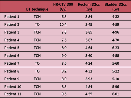
D100 and D90, as the minimum dose delivered to 100% and 90% of the HR-CTV, were considered to assess the planning. In addition, all plans were performed to keep organ at risks (OARs) doses to the largest irradiated volume of 0·1, 1 and 2 cm3 (D0.1cc, D1cc, D2cc) as low as the GEC-ESTRO recommendations. Reference Haie-Meder, Pötter and Van Limbergen15 The prescribed total dose (external radiotherapy + brachytherapy) for HR-CTV ranged between 80 and 90 GyEQD2, depending on the tumour size at the time of brachytherapy. Table 1 presents the treatment planning characteristics of each patient.
Dose volume parameters of the patients in this study

Abbreviations: TCN, tandem cylinder needle; TO, tandem ovoid.
In order to measure ESD, thermoluminescent dosimetry was performed for each patient. TLDs were placed precisely on the patient’s skin along her symphysis pubis bone (anterior) and left (L)/right(R) sides of her pelvic. No dosimeter was placed in the posterior part of the patient’s skin for patient convenience and because of high probability of error.
For each position, three different dosimeters were placed as close as possible to improve the statistical fluctuation of dosimetry results.
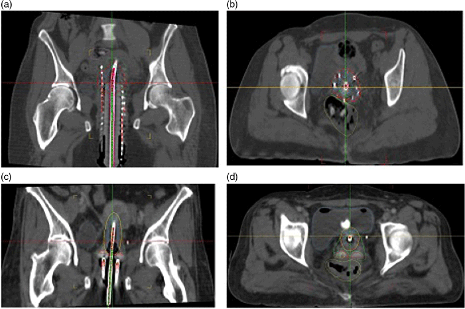
The position of the TLDs was determined using a fiducial marker during CT scan imaging. Next, the dosimeters were placed at these known positions during the first session of the patient’s treatment. With this set-up, it was possible to compare the calculated and measured ESDs obtained from TPS and TLDs, respectively. Figure 1 displays coronal and axial CT images view of two sample patients treated with tandem cylinder needle (TCN) and TO techniques.
Coronal and axial CT images view of two sample patients treated with (a,b) tandem cylinder needle (TCN) and (c,d) tandem ovoid (TO) techniques, respectively.

TLD calibration
The main advantage of using TLD for brachytherapy is its small size in order to obtain an accurate result at each position. In this study, 20 7-LiF:Mg,Cu,P TLDs (commercially known as GR‐207, manufactured by Fimel Co., Velizy, France) were utilised in a circular shape with 0·8-mm thickness and 2-mm diameter. First, TLDs were annealed by the procedure recommended by the manufacturer at 240°C for 10 minutes. Reference Banaee and Nedaie17 Each chip was positioned in specialised holes on a slab of Solid Water™ phantom material at a 2-cm depth. A dose of 100 cGy was irradiated to all TLDs, from a 6-MV photon beam produced by a linear accelerator (Elekta compact, China). A field size of 10 × 10 cm2 and source to surface distance (SSD) = 100 cm were used to acquire the element correction coefficient (ECC). This coefficient was calculated from Equation (1):
 $${\rm{ECC}} = {\rm{ }}{{{\rm{AV}}{{\rm{E}}_{{\rm{TLD}}}}} \over {{\rm{TL}}{{\rm{D}}_i}}}$$
where AVETLD and TLD i represent the average reading value of the total TLDs and individual reading, respectively. After irradiation, all TLDs were read out employing an appropriate reader (Fimel, Velizy, France), according to their ECCs. The read‐out cycle included 140°C for 7 seconds (pre‐heat), 6°C s−1 linear ramp to 245°C for 10 seconds. Reference Banaee and Nedaie17
For TLD dosimetry, the calibration was performed through using 5, 10, 30, 50, 70 and 100 cGy doses. The accuracy of dose calibrations with TLD chips dosimeter was confirmed by a cross-calibration with a Semiflex ionisation chamber (31010, PTW Company, Germany). All irradiated TLDs were read by a TLD reader after 48 hours. These readings were then converted to the dose, using the calibration of the TLD responses.
The TLDs error in comparison with the dose value of TPS was calculated according to the following equation:
 $${\rm{Difference}}\;\left( \% \right) = {\rm{ }}\left( {{{{\rm{ < }}{D_{{\rm{TLD}}}} > - \;{D_{{\rm{TPS}}}}} \over {{D_{{\rm{TPS}}}}}}} \right) \times 100$$
where D TPS represents the dose calculated by TPS, and <D TLD> is the mean absorbed dose value from TLD measurements at each position.
Uncertainty analysis
An uncertainty analysis was performed to evaluate the accuracy of our TLD measurements. The total uncertainty was calculated according to the following equation:
 $${\rm{Total}}\;{\rm{Unertainty}} = \;\root 2 \of {{\sigma _M}^2 + {\sigma _C}^2 + {\sigma _E}^2 + {\sigma _G}^2} $$
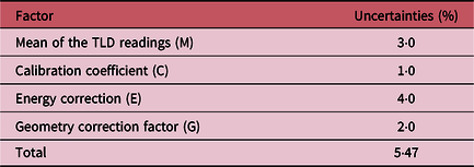
where σM and σC represent the uncertainties related to the mean TLD readings and calibration coefficient, respectively. In addition, σE denotes the uncertainty due to using different energies for calibration (6 MV) and brachy dosimetry (60Co). According to Banaee and Nedaie’s study, Reference Banaee and Nedaie17 the error due to using different energies for this type of TLDs has been less than 4%. Furthermore, the point of interest in this study (skin layer) was closer to the source than the point of measurement (centre of the TLD), so we have had geometry uncertainty (σG) while comparing TLD and TPS results. Raffi et al. Reference Raffi, Davis and Hammer9 have calculated and reported this uncertainty at a level of 2%.
Results and Discussion
TLD calibration curve
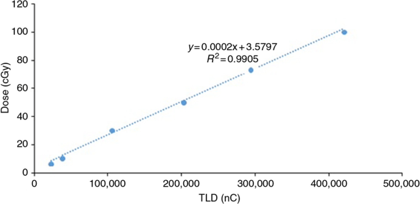
The obtained TLD calibration curve was shown in Figure 2. The uncertainty results from different components affecting the TLD measurements are reported in Table 2.
Determination of TLD calibration coefficient.

Uncertainty results from different components affected on TLD measurements

Kirov et al. Reference Kirov, Williamson, Meigooni and Zhu18 measured the dose rate around an 192Ir source at distances from 5 to 100 mm in a phantom using TLDs. They found that the relative uncertainty was about 5·5% for the TLD dosimetry. The value of relative uncertainty in this study has been consistent with their findings.
Clinical results
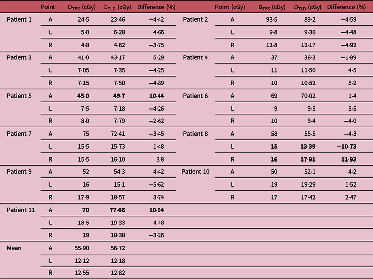
Table 3 presents a comparison between the calculated and measured ESDs obtained from TPS and TLD dosimetry. For each patient, anterior (A), left (L) and right (R) points have been reported for ESD evaluation.
Comparison between measured (TLD) and calculated (TPS) data for exit skin dose of patients (the bold values refer to high errors)

Abbreviations: A, anterior; L, left; R, right.
The skin doses depend on the prescribed dose and patient’s BMI. It means that larger prescribed doses and thinner patients result in a greater dose received by the skin. About 90% of all cases showed a good agreement (while considering TLD uncertainty ∼5·5%) between TPS dose calculations and TLD measurements. This study has demonstrated that TLDs can measure the ESD with an acceptable uncertainty when the proper considerations are applied. Raffi et al. Reference Raffi, Davis and Hammer9 also found the capability of TLD dosimeter as a precise tool in exit skin dosimetry for 192Ir intra-cavitary accelerated partial breast.
Although TLD dosimeters cannot be used in real-time measurements, their lower price than other dosimeters, for example, metal–oxide–semiconductor field-effect transistor (MOSFET) and diodes encourages us to use them as a preliminary assessment in clinical tests. Note that a high error (30–40%) was reported against MOSFET accuracy for distances greater than 50 mm from the source. Reference Palmer, Bradley and Nisbet19
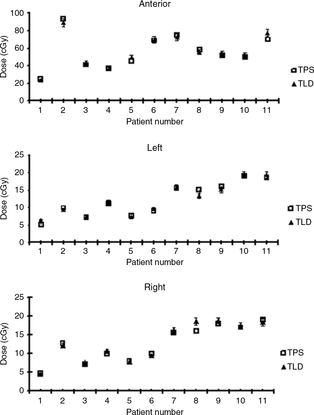
Figure 3 displays the skin doses of each point (A, L and R) for all patients separately. Among our patients, differences between TLD measurements and TPS calculations were higher than the calculated uncertainty level ∼5·5% for three of them. TLD measurements for patients #5 and #11 [both with tandem cylinder needle (TCN) technique] revealed a higher dose of skin (about 10%) in the anterior position than the value previously calculated by TPS. In addition, in patient #8 rises and falls of skin doses were measured in lateral positions (left and right) compared with the calculation. This patient was treated using tandem and ovoid applicators. These errors could have several sources such as movements of markers on the patient’s skin during the patient’s transfer between CT imaging and treatment rooms. Reference Asnaashari, Gholami and Khosravi20 The high-dose gradients in brachytherapy necessitate knowing the position of the detector with at least millimetre precision. In addition, another important issue is the changes in the intra-cavitary applicator positions over the course of the HDR brachytherapy procedure due to the excessive movement caused by patient transfers. GEC-ESTRO reports around 5% dose volume error to both target volume and OAR due to 1-mm applicator displacement. Reference Hellebust, Kirisits and Berger21 Grigsby et al. Reference Grigsby, Georgiou, Jeffrey and Perez22 reported up to 35% of point dose difference due to 1·2-cm displacement of tandem in the caudal–cranial direction. Accordingly, one might attribute the dose increase in the anterior position of patients #5 and #11 to tandem displacement in this direction. Similarly, for patient #8, it seems that the movement of ovoid applicators towards the right direction led to dose rise and fall in the right and left directions, respectively. Recently MR/CT-guided HDR brachytherapy has been suggested by several investigators Reference Andrew, Kim, Ginader, Smith, Sun and Wang23 to monitor the motions of applicators relative to patient’s anatomy. The results of this study also indicate a need of using portal imaging during the treatment. Nevertheless, ESD measurement is a suitable practical approach for verifying the accuracy of treatment delivery in HDR brachytherapy. This method combined with an imaging system has capability of estimating the applicator’s movement.
Skin doses of each point (anterior, left and right) for all patients (with 5% error bar).

Conclusion
The method of ESD measurements presented here offers the possibility of verifying the accuracy of GYN HDR treatment delivery. Meanwhile, determining the position of the detector with respect to the applicator in HDR gynaecological brachytherapy is an important issue. By comparing the measured and calculated data from skin dosimetry in the first session of the patient’s treatment, it is then possible to detect problems in the OAR/applicator geometry and decide to eventually compensate the error in other sessions of the treatment. The dosimetric accuracy of the TLD also allows measuring the skin dose.
In our future study, image-guided technique will be applied to find a correlation between ESD and organ motion/applicator movements during HDR brachytherapy.
Acknowledgements
None.
Conflict of Interest
The authors confirm that this article content has no conflict of interest.