1. INTRODUCTION
The utility and development of space resources is a new an important factor for the rapid growth of China's Gross Domestic Product (GDP) and enhancing national defence strategy. Space resources are gradually becoming a competitive focus for all powerful countries. Research and development on all sorts of space vehicles are acknowledged as the way to promote the nation's space operations capability. The uncertainty and hostility of the space environment makes high demands on the independent viability of space vehicles. In particular, when one high-orbit spacecraft attempts to dock with another, the properties of an autonomous navigation system will be the critical factor in deciding the success of the mission.
In order to reduce launching costs and risk, and ensure spacecraft are more durable and stable, with higher quality operations in the complex space environment, many countries have presented new requirements for in-orbit space services. Space autonomous rendezvous and docking technology would allow in-orbit spacecraft to develop more quickly and reduce the threats of the increasing space debris, which bring benefits for mankind.
At present, a mature and widely-used approach to the autonomous navigation of vehicles is achieved with Global Navigation Satellite System (GNSS) satellites. Because the altitude of GNSS orbits is around 20 000 km, it is effective for the navigation of low-orbit satellites or spacecraft but it does not work for high-orbit spacecraft (i.e., altitudes of more than 20 000 km). Although the United States of America (USA) successfully experimented with the navigation of high-orbit spacecraft using Global Positioning System (GPS) satellite side-lobe signals (Psiaki, Reference Psiaki and Jung2002; Davis, Reference Davis2002), this approach still brought a technological problem to the research on receiver and aerial development for capturing weak signals; this method was not ideal for miniaturisation and installation in space vehicles. Furthermore, GPS satellites do not belong to China, which brings a degree of uncertainty to spacecraft navigation from a national perspective. Space navigation by astronomy has low precision and technology is still immature. Determining orbits based on ground measurements and control equipment include the following factors: high cost, limited spatial coverage, weak real-time capability, poor anti-jamming capability and the inability to achieve autonomous navigation. Therefore, making low-cost, high-precision and high-reliability autonomous navigation for high-orbit spacecraft has been an acute and urgent issue for current research.
The concept of navigation based on transmitting communication satellites was proposed by Ai Guoxiang, academician of the National Astronomical Observatories of Chinese Academy of Sciences (GuoXiang et al., Reference GuoXiang, HuLi, HaiTao, ZhiGang and Ji2009). This navigation approach, with the transmitting function of Earth synchronous orbit communication satellites, sends the ground-generated navigation telegraphy message and ranging code to the users through satellites. This approach substitutes a ground atomic clock with better performance than an in-satellite clock, as the latter is difficult to manufacture and is a high-cost item. This method can also prolong the life cycle of ‘retired’ communication satellites (HuLi et al., Reference HuLi, GuoXiang, YanBen, LiHua, JiBin and JianPing2009a), is a good method of reducing space debris and also provides economic benefits. Based on the above factors, the Chinese Area Position System (CAPS) has been proposed (Xuan et al., Reference Xuan, ZhiGang, XuHai, WenJun, Hui and ChuGang2012). CAPS is a new satellite navigation institution, is China's independent intellectual property and is the first navigation system in the world which uses transmitting satellites of this type. Many scholars have made intensive studies of satellite principles (GuoXiang et al., Reference GuoXiang, HuLi, HaiTao, ZhiGang and Ji2009), satellites constellation layouts (YanBen et al., Reference YanBen, LiHua, QiYuan, ZhiQiang and GuoXiang2009a), ephemeris fast recovery (XuHai et al., Reference XuHai, ZhiGang, ChuGang, Ji, HuLi, GuoXiang, FengLei and RongChuan2009), signal structures (XiaoChun et al., Reference XiaoChun, HaiTao, YuJing and Yu2009), navigation solutions (HuLi and Jun., Reference HuLi and Jun2009b) and receiver developments (YongHui et al., Reference YongHui, Yu, Lei, JingFa and JianFeng2009).
Taking the success of CAPS and the demand of autonomous navigation for high-orbit spacecraft into consideration, this paper proposes a new method that allows communication satellites to achieve autonomous navigation through retransmitting ground-generated navigation signals. The remainder of the paper is arranged as follows: first, the overall design of the navigation system is addressed, then the research on system composition, the operation mode, the constellation framework, the determination of satellite orbits and signal power assurance. Solutions for relevant new problems are provided by analysing different features of CAPS. Then, the study sets up the information integration model of the navigation system based on a Square Root Unscented Kalman Filter (SRUKF) algorithm. Finally, it analyses the precision of the navigation system by simulation.
2. OVERALL DESIGN OF NAVIGATION SYSTEM
2.1 Composition and Operation Mode of System
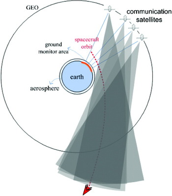
The entire navigation system consists of ground control management, constellation and user interface. The ground control management part includes: ground satellite measurement and control system; high-precision orbit determination system using retransmission satellites; navigation signal generation and transmitting, monitoring and controlling sub-system; ground communication central station; time-frequency standard, error compensation, monitoring and measuring sub-system, and the satellite attitude regulation system. The user's part consists of the receiver system of the spacecraft. The overall schematic diagram of system is shown in Figure 1.
Scheme of navigation system based on retransmission communication satellites to high-orbit spacecraft.

In spacecraft navigation, adjusting the communication satellite's antenna in advance is needed to cover the orbit area of spacecraft, especially the key area, and is based on the orbit of the spacecraft.
2.2. Composition of Constellation
The constellation of the navigation system is made up of Geostationary Earth Orbit (GEO) communication satellites and Inclined Geo-Synchronous Orbit (IGSO) communication satellites. Satellites in the constellation are mainly retired communication satellites. At present, there are plenty of static GEO communication satellites. For those working satellites, ground controlling centres need to issue instructions regularly to adjust orbital positions. When fuel remaining reaches a certain level, the satellite will go into ‘end-of-life’ mode. To ensure that communication systems are not interrupted, the relevant departments will launch new satellites, in advance, to replace the old ones. The old satellites are then retired and become space debris. However, the solar power and signal transponders of retired satellites could still be used for many more years. These satellites could provide an abundant GEO constellation for a retransmission navigation system. In addition, if controlling centres stop maintaining and adjusting the southern and northern position of retired satellites but simply maintain and adjust the eastern and western position, retired GEO satellites could increasingly turn into IGSO satellites with dynamic interaction of lunisolar perturbation. Certainly, retired GEO satellites could be regulated into special parameter IGSO satellites if needed. Those satellites could provide cheap IGSO satellite constellation for the retransmission navigation system. Combination with satellites in different orbits would ensure a good geometric configuration of space position reference (YanBen et al., Reference YanBen, LiHua, QiYuan, ZhiQiang and GuoXiang2009a; YanBen et al., Reference YanBen, LiHua, QiYuan, ZhiQiang, HuLi and GuoXiang2009b).
2.3. Determination of the Satellite Orbit
The proposed navigation system in this paper is different from CAPS because each communication satellite needs to have at least two more optional transmit antennas. The ground control centres select the appropriate antennas and divide signal into two beams, then send them to the ground stations and space reservation areas, respectively. The random error of measurement of the distance from the satellite to ground station is less than 10 cm (1σ), the error of determining satellite position is less than 2·0 m (1σ), and the error of orbit prediction (2 h) is less than 2·5 m (1σ) by using navigation signals which are sent back to the ground and the Two Way Satellite Time Contrast (TWSTC) (GuoXiang et al., Reference GuoXiang, HuLi, HaiTao, ZhiGang and Ji2009) approach. After the communication satellite orbits have been manoeuvred or their attitudes adjusted as needed, the rapid recovery of the satellite ephemeris can be achieved by using intensive short-arc observation data and statistical orbit determination methods for orbit prediction. The orbital precision is about 3 m, when forecasting 2 hours ahead by using 30 minutes data (XuHai et al., Reference XuHai, ZhiGang, ChuGang, Ji, HuLi, GuoXiang, FengLei and RongChuan2009).
In addition, the retransmission satellite navigation system adopts a virtual atomic clock technology. The virtual clock's pseudo-range difference function can reduce the impact of ephemeris error on the results of the navigation. The virtual clock's pseudo-range difference function will cancel the projections of ephemeris error on the navigation uplink station, on the high-orbital spacecraft and the satellite connection (XiaoHui et al., Reference XiaoHui, HaiTao, YuJing and DanNi2009). Therefore, when the angle (α) between the master control station, the satellite and the spacecraft is equal to 0°, the ephemeris error's impact can be ignored. The impact can be estimated by Equation (1):

where:
ε o stands for the equivalent range error introduced by the ephemeris error.
b and a stand for the projections of ephemeris error on the master control station (the satellite connection and its vertical direction, respectively).
 , dr stands for the actual ephemeris error.
2.4. Signal Structure and Firm Power
The signal structure is the same as that adopted by CAPS and C-band is used to navigate (XiaoChun et al., Reference XiaoChun, HaiTao, YuJing and Yu2009). The reference frequency is 10·23 MHz and the adopted frequency points are:
• Uplinks: C1=(6368·15±15) MHz and C2=(6051·02±15) MHz.
• Downlink: C1=(4143·15±15) MHz and C2=(3826·02±15) MHz.
The navigation information mainly includes temporal information, synchronous information, the model parameters of the virtual atomic clock (clock information), satellite orbit parameters (ephemeris information) and other information.
Three ranging codes are used:
• For the Coarse Code, the code rate is 1·023 MHz; the code period is 1 ms, and the code length is 1023.
• For the Precise Code 1, the code rate is 5·115 MHz, the code period is 10 ms, and the code length is 51150.
• For the Precise Code 2, the code rate is 10·23 MHz, the code period is 1 s, and the code length is 10, 230,000.
In order to ensure that the receiver can work properly, the received Carrier to Noise (C/N) ratio is required to be above the threshold with a certain margin. The C/N ratio of the signal received by the receiver is estimated in the following parts. The C/N ratio can be expressed as:
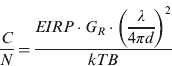
As decibels, Equation (2) can be written as:

where:
EIPR stands for the Effective Isotropic Radiated Power (EIRP) of the communication satellites.
G R is the antenna gain of the receiver.
T is the effective noise temperature.
k is the Boltzmann constant.
B is the equivalent noise bandwidth.
L=(4πd/λ)2 is the transmission loss.
λ is the wavelength of the carrier wave.
d is the distance between the satellite and the receiver.
If the EIPR of the communication satellite is 36 dBW, the ratio of the receiver's antenna gain and noise temperature as −20·21 dB/K, the equivalent noise bandwidth as 72 dBHz, the carrier frequency as 4158·15 MHz and the distance from the receiver to the satellite as 105 km, we will gain the C/N −32·43 dB through calculation. If the receiver demodulation threshold is designed to be −45·14 dB, from the results we can see that the receiver can still work properly 105 km away from the communication satellite.
2.5. Ranging and Velocity Measurement Based on the Virtual Atomic Clock Technology and Dual Frequency Difference
Similarly to CAPS, the proposed navigation system also uses a virtual atomic clock technology for the pseudo-code ranging (GuoXiang et al., Reference GuoXiang, HuLi, HaiTao, ZhiGang and Ji2009). The virtual clock can be implemented through indirect or direct measurement method and the two methods have the same precision. Using the direct measurement method by measuring the integrated baseband delay τ mt, transmit channel delay τ t, uplink delay t ij and transponder delay τ s, we can gain access to the conversion time correction amount τ CLK of the virtual clock.

By using the indirect measurement method, τ CLK can be expressed as:

In this formula, τ cc is circuit delay (integrated baseband transmitter terminal, communication satellites, integrated baseband receiving terminal); τ down is downlink signal delay (including delays caused by geometric path and atmosphere); τ r is receive channel delay.
With the Earth-centred inertial reference frame J2000 as the reference coordinate system, the observation equation the receiver uses to measure the pseudo-range can be expressed as:

where:
ρ j is the pseudo-range measurements corresponding to the j communication satellite.
X r is the receiver's position value coordinate.
X j refers to the position coordinate of the communication satellite.
c stands for the signal propagation speed.
δt r is the receiver clock error.
ε j is the measurement random noise.
As the frequency drift of the satellite transponder will lead to the instability of the carrier frequency and impact the velocity measurement accuracy, we can improve the velocity measurement precision through the difference between the dual frequency signals (GuoXiang et al., Reference GuoXiang, HuLi, HaiTao, ZhiGang and Ji2009).
If we set f 1, f 2 as the frequency of the two navigation signals generated by the ground master control station; V G, VS and V r respectively as the velocity vectors of the ground control station, the communication satellite and the carrier receiver, e GS as the unit vector from transmitting antenna phase centre in the ground master control station to receiving antenna phase centre in the communication satellite; e Sr as the unit vector from the communication satellite to antenna electrical phase centre of the high orbit spacecraft's receiver; f L0 as the local frequency of the communication satellite transponder, and Δf as the unknown frequency drift of the transponder, the transmitted frequency after the communication satellites receive the navigation signals will be:


the frequency the receiver receives:


written as:

From the difference of f 1r and f 2r, we will gain the stable value Δf 12r free from the transponder frequency drift:

3. THE INFORMATION FUSION ALGORITHM OF THE NAVIGATION SYSTEM
The observation information in the navigation algorithm is the pseudo-range and pseudo-range variability, and the observation equation has nonlinear characteristics as Equation (6) and Equation (8) show. In order to provide high-precision navigation data for the high orbital spacecraft in real time, using SRUKF algorithm, we integrate the observation information and the dynamic equation of the spacecraft orbit tightly. The SRUKF algorithm can effectively reduce the impact caused by the accumulation of rounding errors; meanwhile it has higher navigation accuracy for the nonlinear system than for the Extended Kalman Filter (EKF).
For the purpose of simplification, we assume that the aircraft is in the state of unpowered gliding and the acceleration could be negligible. The state of the navigation system is composed of the receiver's position, velocity, clock error and clock error variability, namely X=[r,v,cδt,cδf]T. In the J2000 coordinate system (the i system), the state equation of the navigation system can be expressed as:
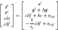
where:
ri, vi are the spacecraft's position vector and velocity vector in the i system.
gi is the Earth's gravitational acceleration vector value of the spacecraft's location in the i system, calculated by ri, taking the terrestrial gravitational perturbation of item J2 into account.
Δg is the equivalent noise of the Earth's perturbation force except for the perturbation item J2.
δt is the receiver's clock error.
δf is the receiver's clock variability.
τ f is the anti-correlation time of the receiver's clock variability.
n cδt and n c δ f are the thermal noises.
h is the clock frequency correction after considering the effect of relativistic effect.
4. SYSTEM SIMULATION AND RESULTS ANALYSIS
4.1. Simulation Conditions
In the Earth-centred inertial reference frame J2000, at the initial time, the height of the spacecraft is 26518·7 km and the simulation time is 104 s, the altitude becomes 39976·8 km when it finally flies away from the Earth. At the initial time, the high orbital aircraft's position and velocity vectors  , (respectively in the units of m and m/s) are:

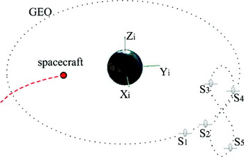
Five communication satellites comprise the navigation system. In the first moments, the relative position relationship between five communication satellites, the spacecraft and the Earth is shown in Figure 2, where S1 and S2 are GEO satellites, whose sub-stellar points are respectively in 85°E and 107°E. Therein, S3, S4 and S5 are IGSOs with the orbit inclination angle 40°, sub-stellar track ‘8’ shaped, the centre in 120°E and the phase difference between the three stars 120°.
The relative position between communication satellites, the spacecraft and the earth at the initial time.

The orbit determination error of the communication satellite is about 3 m; the precision of the virtual atomic clock is 4 ns; the mean square deviation of the pseudo-range measurement noise is set to 5 m; the mean square deviation of the velocity measurement noise is 0·1 m/s. The first two errors among them are systematic errors during the navigation process. The measuring frequency is 1 Hz and the receiver's clock is implemented by the crystal oscillator with the stability of 10−6.
The error of the filter in the initial state is:

4.2. Simulation Results and Analysis
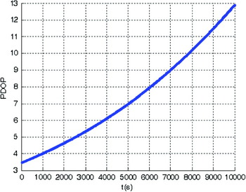
The variation of Position Dilution of Precision (PDOP) during the flight is shown in Figure 3.
The variation of PDOP during the flight.

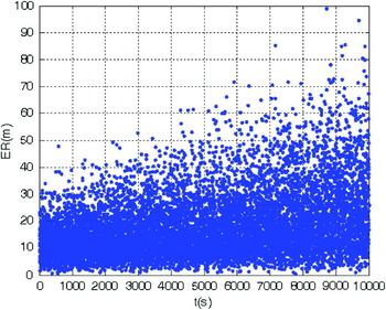
The positioning error of the spacecraft on single epoch is shown in Figure 4, where ‘ER’ stands for the actual positioning error and ‘t’ stands for flying time.
The positioning error on single epoch.

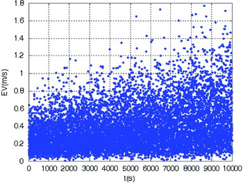
The velocity error of the spacecraft on single epoch is shown in Figure 5, where ‘EV’ stands for the actual velocity error and ‘t’ stands for flying time.
The velocity error on single epoch.

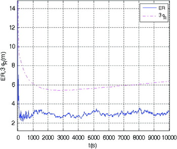
The positioning error curve of the spacecraft after filtering is shown in Figure 6, where ‘ER’ stands for the actual positioning error, ‘3σ R’ stands for three times the mean square error of positioning error and ‘t’ stands for flying time.
The filtered positioning error curve.

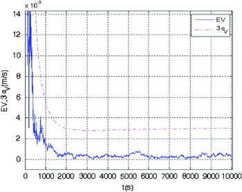
The velocity error curve of the spacecraft after filtering is shown in Figure 7, where ‘EV’ stands for the actual constant velocity error, ‘3σ V’ stands for three times the mean square error of constant velocity error and ‘t’ stands for flying time.
The filtered constant velocity error curve.

From the simulation results, it is seen that the high precision navigation for the high-orbital spacecraft can be achieved by using five communication satellites with the simple antenna adjustment strategy. In the worst situation, the value of PDOP reaches 13, and the single point positioning error and velocity error are less than 100 m and 1·8 m/s, respectively. After filtering, the mean square deviation of the spacecraft's positioning error can be decreased from 5197·3 m to 2·6 m within 300 s. The final mean square deviation of the positioning can be up to 2·1 m, and the actual positioning error is 3·2 m; the mean square deviation of the velocity can be decreased from 5·197 m/s to 0·009 m/s within 300 s. The final mean square deviation of the velocity can be up to 0·0011 m/s, and the actual velocity error is 0·0003 m/s. The above data shows that the convergence speed of the filtering algorithm is fast.
It can be inferred from the simulation results that better navigation results can be obtained by basing on the area of spacecraft and optimizing the choice of the constellation. The volume size of the covered areas, the requisite number of satellites, the reliability of the system and other factors should be taken into consideration in the optimization process.
5. CONCLUSION
China has independently innovated the application of a navigation method for the high orbital spacecraft, based on transponding satellites and this paper explains the overall design of the navigation system. Based on the method of the SRUKF, a navigation information fusion model is built and a simulation analysis of the result of the navigation system is provided. The simulation results show that the proposed navigation algorithm is characterized by fast convergence speed and high precision. After a period of filtering, the positional precision of the spacecraft at an altitude of 40 000 km can be within 2·6 m, with a velocity precision of 0·0011 m/s.
The transponding satellite navigation method greatly reduces the development costs by using communication satellites in high-orbit spacecraft navigation instead of launching special navigation satellites. Moreover, the signals of transponding satellite navigation are generated from the ground, which is very convenient and cost-effective for system maintenance. In addition, placing atomic clocks on the ground may also help improve the clock accuracy achieved.
When using the transponding satellites navigation system, no less than four well geometrically-configured communication satellites need to be selected in advance, according to the orbit of the spacecraft (the number of satellites could be increased in order to improve the system reliability). Then, the antennae of the satellites need to be adjusted to ensure the short-term coverage of the critical section of the spacecraft's orbit. In addition to the characteristics of simple implementation, high precision, low investment and strong anti-interference capability, the transponding satellite navigation system also has the advantages of the high orbit character of communication satellites and an expanded coverage of the spacecraft's space region; neither of these capabilities are found in other navigation systems. The results of this study can provide strong technical support for autonomous rendezvous and docking of high orbital spacecraft and other application fields.