I. INTRODUCTION
Wireless power transfer (WPT) is an emerging technology and has been used in many applications because of its convenience, simplicity, and safety. Some big companies, such as Apple and Samsung, have funded advanced research and development of WPT technologies for their portable electronics. Due to the mobility of these devices, a three-dimensional (3D) WPT system with higher spatial freedom is expected. One solution is using multiple transmitter coils to generate magnetic fields in different directions and synthesize the resultant magnetic field by controlling the currents in the transmitter coils.
Eun S. Lee et al. [Reference Lee, Choi, Sohn, Lim and Rim1–Reference Lee, Sohn, Choi, Han and Rim4] utilized crossed dipole transmitter coils to generate direct and quadrature (DQ) magnetic field, which guarantees both free positioning and omnidirectional powering over a wide area of the transmitter coils. Pratik Raval et al. [Reference Raval, Kacprzak and Hu5–Reference Raval, Kacprzak and Hu7] proposed a multiphase inductive power transfer box with a rotating magnetic flux inside to charge the low-power battery. Wai Man Ng et al. [Reference Ng, Zhang, Lin and Ron Hui8–Reference Zhang, Lin and Ron Hui11] introduced two kinds of 3D WPT systems, and one system consists of two orthogonal circular coils while another system consists of three orthogonal circular coils. In order to improve the transfer distance and efficiency of high spatial freedom WPT system, Yongseok Lim et al. [Reference Lim, Ahn and Park12–Reference Lim and Park13] proposed a WPT system with two crossed square coils based on active magnetic field shaping technique. However, the direction of the shaped magnetic field is limited to a 2D plane. In order to further improve the system dimension to 3D, Qi Zhu et al. [Reference Zhu, Su, Sun, Tang and Hu14] proposed a WPT system with three crossed square coils to realize full range field orientation in the space, the magnitude, and direction of the shaped magnetic field are controlled by adjusting the amplitude and phase angle of currents flowing in the transmitter coils. The power pick-up around the space of the transmitter coils is charged by this active current-controlled field orientation method. However, once the size and the current carrying capability of the transmitter coils are fixed, the induced voltage of the receiver coil at a defined distance is also fixed. In order to further increase the induced voltage of the receiver coil or expand the transfer distance with the induced voltage of the receiver coil maintained, the magnetic field distribution around the given transmitter coils is shaped by using magnetic materials.
This paper proposes a 3D wireless charging cube with three orthogonal coils and supporting magnetic cores to enhance the magnetic flux outside the cube. The magnetic cores are used to enhance the magnetic field distribution outside the charging cube for extended power transfer range of a 3D WPT system. The effects of the magnetic cores, and their width and permeability on the magnetic field outside the cube, as well as the induced electromotive force, are investigated by simulation and experimental studies.
The rest of the paper is organized as follows: In Section II, the proposed 3D wireless charging cube is introduced. In Section III, the magnetic field distribution analysis is demonstrated. In Section IV, the simulation studies are given. In Section V, the experimental studies are given. In Section VI, the conclusion is drawn.
II. PROPOSED 3D WIRELESS CHARGING CUBE
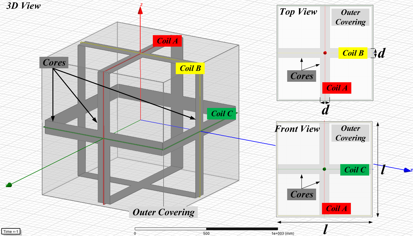
The proposed 3D wireless charging cube is shown in Fig. 1, where d means the width of each magnetic core, l means the length of each magnetic core (as well as the length of each side of the cube), the thickness of each magnetic core is negligible, and each contour has its corresponding magnetic core. A magnetic core is closely attached to each contour, but it should be noted that every magnetic core is located in the inner area of transmitter coils and perpendicular to the plane of the transmitter coil. The transmitter coils and magnetic cores are covered by an outer covering whose material has no effect on the distribution of the magnetic field in the space. In the rest of the paper, the outer covering will not be shown again for clear observation.
Proposed 3D wireless charging cube with three orthogonal coils and supporting magnetic cores.

As known, the magnetic field is conservative in loops. The magnetic field close to each contour curls and has no contribution to the magnetic field synthesis outside the cube, such feature leads to higher magnetic flux density inside the cube and lower magnetic flux density outside the cube. The proposed 3D wireless charging cube with three orthogonal coils and supporting magnetic cores changes the distribution of the magnetic field in the space to extend the range of 3D wireless charging.
III. MAGNETIC FIELD DISTRIBUTION ANALYSIS
A) Magnetic field shaping without magnetic cores
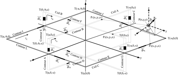
In order to maximize the coupling between the transmitter and receiver coils and minimize the coupling among the transmitter coils, the three transmitter coils are mutually orthogonal and have the same length (a = b = c) as shown in Fig. 2. This structure keeps the coupling among the transmitter coils as low as possible and avoids magnetic resonance failure when magnetic coupling occurs among transmitter coils.
Block diagram of the structure with three orthogonal transmitter coils.

According to Fig. 2, the coil A, B, and C lie on the plane XOZ, YOZ, and XOY, respectively. Assume that three currents through coils A, B, and C are I Acos(ωt), I Bcos(ωt + Δθ 1) and I Ccos(ωt + Δθ 2), respectively. Based on Biot-Savart Law, the magnetic flux density components generated by coil A, B, and C at point P can be calculated.
In order to simplify the analysis of B-field synthesis in the space, including the magnitude and direction, taking the geometric center of three transmitter coils p o(0, 0, 0) as the example to discuss the B-field. Because each transmitter coil is square, let a = b = c = l. The magnetic field at p o(0, 0, 0) is described by using spherical coordinates as follows [Reference Lin, Zhang and Ron Hui10]:
 $$\left\{ {\matrix{ {R_{p_o} = \displaystyle{{\sqrt 2 {\rm \mu}_0N} \over {\pi l}}\sqrt {I_A^2 {\rm co}{\rm s}^2(\omega t) + I_B^2 {\rm co}{\rm s}^2(\omega t + \Delta \theta_1) + I_C^2 {\rm co}{\rm s}^2(\omega t + \Delta \theta_2)}} \cr {\theta_{p_o} = {\rm ta}{\rm n}^{-1}\left( {-\sqrt {I_A^2 {\rm co}{\rm s}^2(\omega t) + I_B^2 {\rm co}{\rm s}^2(\omega t + \Delta \theta_1)} /I_C{\rm cos}(\omega t + \Delta \theta_2)} \right)} \cr {\varphi_{p_o} = {\rm ta}{\rm n}^{-1}(\; I_A{\rm cos}(\omega t)/I_B{\rm cos}(\omega t + \Delta \theta_1))} \cr}} \right.$$
where μ0 is permeability of vacuum, valued 4π × 10−7N · A −2. N is the number of turns of each coil.  $R_{p_o}$ is the magnitude of B-field at point p o,
 $\theta _{p_o}$ is the angle between the zenith direction and the direction of B-field, and
 $\varphi _{p_o}$ is the signed angle measured from the azimuth reference direction to the orthogonal projection of the direction of B-field on the reference plane (
 $R_{p_o} \gt 0,\; 0 \le \theta _{p_o} \le \pi, \; 0 \le \varphi _{p_o} \le 2\pi $).
B) Effect of magnetic cores
The magnetic cores with high magnetic permeability have a stronger ability to guide the magnetic flux compared with the air. Due to the existing of magnetic cores, the rotation radius of the magnetic flux close to a contour will be increased. In other words, the curl of magnetic flux has been suppressed and the magnetic flux has been straightened. The proposed configuration of three orthogonal transmitter coils with magnetic cores limits the magnetic flux inside the magnetic cores and changes the route of magnetic flux close to each contour, which results in reducing the magnetic flux density inside the cube and increasing the magnetic flux density outside the cube.
Regarding the effect of a magnetic core, it is not possible to analytically build an explicit modeling of a magnetic core by quantitative values. Instead, it will be identified by simulations that the magnetic cores adapted to the transmitter coils further enhance the distribution of the magnetic field generated by three orthogonal crossed-loop coils [Reference Nguyen, Lee, Choi and Rim15].
IV. SIMULATION STUDIES
A) 3D wireless charging without magnetic cores
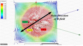
Based on equation (1), assume that the length of the side of each coil is 1 m, the number of turns of each coil is 10, ω = 200000π rad/s (f = 100 KHz), and I A = I B = I C =  $15\sqrt 2 $ A, Δθ 1 = Δθ 2 = 0. Hence, the direction of the formed magnetic field is θ = 55°, φ = 45°. The corresponding distribution of B-field in the plane φ = 45° at t = 2.5 µs is simulated in software “Ansoft Maxwell”, shown in Fig. 3. All the simulation parameters will be used in the following simulations. It is obvious that the WPT system with three crossed-loop coils can shape the magnetic field in the space.
Simulation of B field under l = 1 m, N = 10, f = 100 KHz,  ${\bf I}_{\bf A}$ =
 ${\bf I}_{\bf B}$ =
 ${\bf I}_{\bf C}$ =
 $15\sqrt 2 $ A and
 $\Delta {\bf \theta} _1$ =
 $\Delta {\bf \theta} _2$ = 0 at t = 2.5 µs.

B) Effect of magnetic cores on field distribution
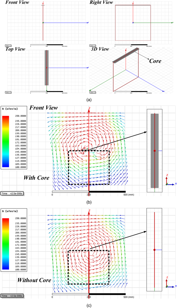
The effect of a magnetic core on the magnetic flux generated by a current-carrying conductor is shown in Fig. 4, where Fig. 4(a) shows the detailed structure of a current-carrying conductor with a magnetic core. The magnetic core is made of ferrite in this paper, which has high permeability and low conductivity. Let the width of magnetic core d and the length of the magnetic core l be 100 and 980 mm, and set the thickness of the magnetic core as 2.5 mm. From Figs 4(b) and 4(c), it is obvious that the magnetic flux of the black dotted box in Fig. 4(b) is straighter than that in Fig. 4(c), which means the magnetic flux close to a contour will contribute to the synthesis of the magnetic field, instead of just rotating around a contour with a small radius and being wasted. The magnitude of B-field in the black dotted box of Fig. 4(b) is smaller than that of Fig. 4(c). The existing of magnetic cores can change the distribution of the magnetic field and straighten the magnetic flux.
Effect of a magnetic core on the magnetic flux generated by a current carrying conductor.

C) Extension of magnetic field range
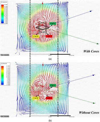
The difference of B-field distribution in the plane φ = 45° at t = 2.5 µs between the transmitter coils with magnetic cores and the transmitter coils without magnetic cores is shown in Fig. 5, and the magnetic cores are made of ferrite. Let the width of each magnetic core d and the length of each magnetic core l be 100 and 980 mm, and set the thickness of each magnetic core as 2.5 mm. From Fig. 5, taking the black dotted line as the baselines, it is obvious that the red area (red means high magnitude of B field) in Fig. 5(a) is larger than the red area in Fig. 5(b), which means the new configuration of transmitter coils with magnetic cores can improve the magnitude of B field at a certain point and extend the transfer distance to some extent when the requirement of the magnitude of B field is constant.
Difference between the transmitter coils with magnetic cores and the transmitter coils without magnetic cores.

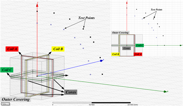
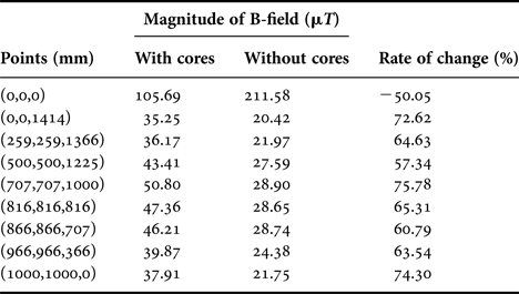
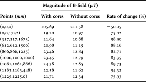
In order to further demonstrate the performance of transmitter coils with magnetic cores, the center point (00,0) and two sets of points have been selected to test the B-field. Each set of points has eight points, and all the points are in the coordinates shown in Fig. 2. Set I is: (0,0,1414 mm), (259, 259, 1366 mm), (500, 500, 1225 mm), (707, 707, 1000 mm), (816, 816, 816 mm), (866, 866, 707 mm), (966, 966, 366 mm) and (1000, 1000 mm, 0), and Set II is: (0,0,1732 mm), (317, 317, 1673 mm), (612, 612, 1500 mm), (866, 866, 1225 mm), (1000, 1000, 1000 mm), (1061, 1061, 866 mm), (1183, 1183, 448 mm) and (1225, 1225 mm, 0). Because I A = I B = I C =  $15\sqrt 2 $ A, Δθ 1 = Δθ 2 = 0, the direction of the formed magnetic field is θ = 55°, φ = 45°. All the points are in the plane φ = 45°. Set I is on the circumference of x 2 + y 2 + z 2 = 2000000, x = y, and Set II is on the circumference of x 2 + y 2 + z 2 = 3000000, x = y. In other word, the eight points in each set are corresponding to θ = 0, 15°, 30°, 45°, 55°, 60°, 75°, and 90°. All the points are shown in Fig. 6. The magnitudes of B-filed with magnetic cores or without magnetic cores at t = 2.5 µs for Set I are shown in Table 1, and the magnitudes of B-filed with magnetic cores or without magnetic cores at t = 2.5 µs for Set II are shown in Table 2. In both cases, d = 100 mm, l = 980 mm, and the magnetic cores are made of ferrite.
Two sets of points for testing the magnitude of B-field.

Magnitudes of B-filed with/without magnetic cores for Set I.

Note: d = 100 mm, l = 980 mm, and the magnetic cores are made of ferrite. Rate of change = (with cores - without cores)/ without cores.
Magnitudes of B-filed with/without magnetic cores for Set II.

d = 100 mm, l = 980 mm, and the magnetic cores are made of ferrite. Rate of change = (with cores - without cores)/ without cores.
Based on equation (1), with the parameters shown in Fig. 3, the numerical result of the magnitude of B-field without magnetic cores at the center (00,0) is 207.85 µT, which is consistent with the simulation result of the magnitude of B-field without magnetic cores at the center (00,0). From Table 1, the magnetic cores have increased the magnitudes of B-field at the point 1.41 m away from the center of transmitter coils by more than 50%. From Table 2, the magnetic cores have increased the magnitudes of B-field at the point 1.73 m away from the center of transmitter coils by more than 75%. At the same time, the magnetic cores have reduced the magnitude of B-field inside the cube is reduced by about 50%. The magnetic cores strengthen the magnitude of the magnetic field outside the cube and weaken the magnitude of the magnetic field inside the cube.
D) Effect of width of magnetic cores
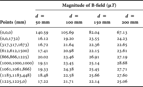
The length of each magnetic core is designed approximately equal to the length of each transmitter coil to make sure that the magnetic field generated by each contour can be shaped, so the length of each magnetic core can be regarded as constant. However, for the width of each magnetic core, it can be changed for better performance. The magnitudes of B-filed with magnetic cores at t = 2.5 µs when d = 50 mm, 100, 150, and 200 mm are shown in Table 3, where l = 980 mm.
Magnitudes of B-filed with different width of magnetic core.

l = 980 mm, and the magnetic cores are made of ferrite.
Table 3 shows the magnitude of B-field outside the cube increases with d; and the magnitude of B-field inside the cube reduces with d. A larger d helps to enhance the external magnetic field, however, it would limit the range of magnetic field orientation of 3D WPT system. When the angle between the zenith direction and the direction of B-field θ (see Fig. 2) is approaching to 0, 90° and 180°, or the signed angle measured from the azimuth reference direction to the orthogonal projection of the direction of B-field on the reference plane φ (see Fig. 2) is approaching to 0, 90°, 180°, and 270°, the synthetic magnetic field formed by 3D WPT system may be blocked by the magnetic cores if they are too wide. In these situations, part of the B field would be shielded which would degrade the system orientation performance in space. In other words, a larger d would strengthen the overall magnetic field outside, but it would compromise the field orientation. As a result, the value of d needs to be carefully designed according to different application requirements.
E) Effect of permeability of magnetic cores
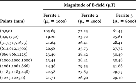
Different material has different permeability, and the magnetic core made of different material has a different effect on the system performance. The magnitudes of B-filed with magnetic cores made of three different ferrites at t = 2.5 µs are shown in Table 4, where d = 100 mm, l = 980 mm. These three ferrites have different permeability 1000, 4000, and 8000, but all of them have quite low conductivity so that the effect of conductivity of these ferrites on the field distribution can be ignored.
Magnitudes of B-filed with different permeability of magnetic core.

d = 100 mm, l = 980 mm.
Table 4 shows that a higher permeability of the magnetic core helps to increase the B-field outside the cube, while the B-field inside the cube is reduced. By considering the effect of the width of the magnetic core, a better performance can be achieved by selecting an appropriate d and a material with higher permeability, which means that the abilities of enhancement and orientation of magnetic field can be realized at the same time. However, the saturation of the material with high permeability and the cost need to be considered in choosing the material of the magnetic cores.
V. EXPERIMENTAL STUDIES
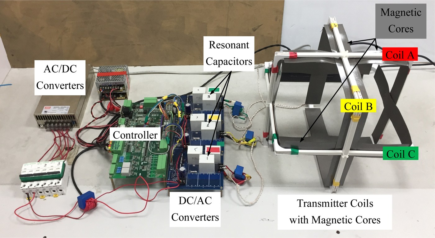
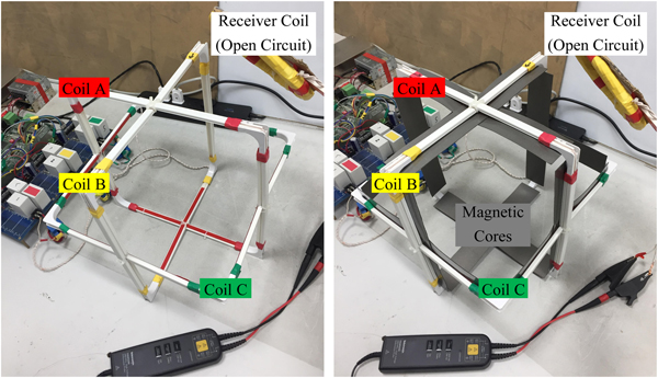
Figure 7 shows a downsized 3D wireless charging setup with magnetic cores. The system includes a controller equipped with a floating-point digital signal processor (DSP, TMS320F28335) and a field programmable gate array(FPGA, EP2C8J144C8N), an AC/DC converter with three independent channel 12 V output, three independent controllable DC/AC converters, three independent resonance tanks including series resonant capacitors and transmitter coils, and one receiver coil for testing the magnitude of B-field. In the experiments, it is not easy to directly measure the magnetic flux density; hence, the induced electromotive force induced in the receiver coil is used to indirectly measure the magnitude of B-field in the region of the receiver coil, the experimental setup for measuring the induced electromotive forces in the receiver coil is shown in Fig. 8. The inductance of each transmitter coil is 10uH, and the inductance of the receiver coil is 245uH. The number of turns of each transmitter coil is 3, and the number of turns of the receiver coil is 30. The length of each transmitter coil is 328 mm, and the currents flowing in three transmitter coils are the same and 10Arms@20kHz.
Downsized 3D wireless charging setup with magnetic cores.

Experimental setup for measuring the induced electromotive forces in the receiver coil.

In the following experiments, three types of ferrites with different width and permeability will be used as the magnetic cores, and all of them have very low conductivity. The detailed parameters of the three ferrites used during the experiments are shown in Table 5.
Detailed parameters of the three ferrites used during the experiments.

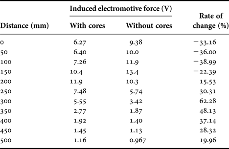
Experiment 1 According to equation (1), the direction of the formed magnetic field is θ = 55°, φ = 45°. Hence, the receiver coil is placed vertical to the direction vector of B-field when the distance between the center of the receiver coil and the center of three transmitter coils changes from 0 to 500 mm. In this experiment, the magnetic core II is used. The induced electromotive forces in the receiver coil with/without the magnetic cores under different distance between the center of the receiver coil and the center of three transmitter coils are shown in Table 6.
Induced electromotive forces in receiver coil with/without magnetic cores under different distances.

The length of each transmitter coil is 328 mm, the length, width, thickness, and relative permeability of magnetic core II are 300, 50, 1 mm, and 2800, respectively. The currents flowing in three transmitter coils are the same and 10Arms@20kHz. Rate of change = (with cores - without cores)/ without cores.
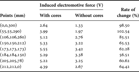
Experiment 2 The center of the receiver coil is placed at some different points in the region 0 ≤ θ ≤ π/2, 0 ≤ φ ≤ π/2 when the distance between the center of the receiver coil and the center of three transmitter coils remains 300 mm. The plane where the receiver coil is located is always kept vertical to the vector from the center of three transmitter coils to the center of the receiver coil. In this experiment, the magnetic core II is used. The induced electromotive forces in the receiver coil with/without the magnetic cores at different points are shown in Table 7.
Induced electromotive forces in receiver coil with/without magnetic cores at different points.

The length of each transmitter coil is 328 mm, the length, width, thickness, and relative permeability of magnetic core II are 300, 50, 1, mm, and 2800, respectively. The currents flowing in three transmitter coils are the same and 10Arms@20kHz. Rate of change = (with cores - without cores)/ without cores.
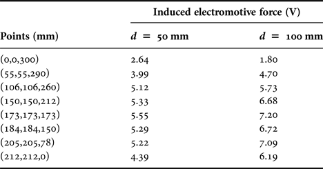
Experiment 3 To study the effect of the width of the magnetic cores on system performance, magnetic cores II and III are used in this experiment. The center of the receiver coil is placed at the same points shown in Table 7, and the plane where the receiver coil is located is always kept vertical to the vector from the center of three transmitter coils to the center of the receiver coil. The induced electromotive forces in the receiver coil with different width of magnetic cores are shown in Table 8.
Induced electromotive forces in receiver coil with different width of magnetic cores.

The length of each transmitter coil is 328 mm. The length, width, thickness and relative permeability of magnetic core II are 300, 50, 1 mm, and 2800, respectively. The length, width, thickness and relative permeability of magnetic core III are 300, 100, 1 mm, and 2800, respectively. The currents flowing in three transmitter coils are the same and 10Arms@20kHz.
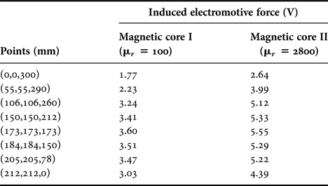
Experiment 4 To study the effect of the permeability of the magnetic cores on system performance, magnetic cores I and II are used in this experiment. The center of the receiver coil is placed at the same points shown in Table 7, and the plane where the receiver coil is located is always kept vertical to the vector from the center of three transmitter coils to the center of the receiver coil. The induced electromotive forces in the receiver coil with different permeability of the magnetic cores are shown in Table 9.
Induced electromotive forces in receiver coil with different permeability of magnetic cores.

The length of each transmitter coil is 328 mm. The length, width, thickness and relative permeability of magnetic core I are 300, 50, 1 mm, and 100, respectively. The length, width, thickness and relative permeability of magnetic core II are 300, 50, 1 mm, and 2800, respectively. The currents flowing in three transmitter coils are the same and 10Arms@20kHz.
As suggested by simulation results, Tables 6 and 7 show that the induced electromotive force in the receiver coil outside the cube is increased with the existing of the magnetic cores, the power transfer distance outside the cube for getting the same induced electromotive force in the receiver coil is extended approximately by 50 mm. Table 8 shows that the induced electromotive force in the receiver coil outside the cube is increased with the increase of the width of the magnetic cores, the induced electromotive force in the receiver coil at the point (173, 173, 173 mm) is increased by about 2V when the width of the magnetic cores is increased from 50 to 100 mm. Table 9 shows that the induced electromotive force in the receiver coil outside the cube is increased with the increase of the permeability of the magnetic cores, the induced electromotive force in the receiver coil at the point (173, 173, 173 mm) is increased by about 2V when the permeability of the magnetic cores is increased from 100 to 2800.
VI. CONCLUSIONS
This paper proposes a 3D wireless charging cube with three orthogonal coils and supporting magnetic cores to enhance the magnetic flux outside the cube for extended power transfer range. Both simulation and experimental results have shown the proposed 3D wireless charging cube can effectively increase the magnitude of B-field outside the cube. It has found that the magnitude of B-field outside the cube can be increased by increasing the width and the permeability of the magnetic cores. The measured results show that when the permeability of the magnetic cores is fixed, the induced electromotive force in the receiver coil at a point 300 mm away from the center of the cube is increased by about 2 V when the width of the magnetic cores is increased from 50 to 100 mm. These results can be used to guide the practical design of range-extended 3D WPT systems in the future.
ACKNOWLEDGEMENT
This work was supported in part by the National Natural Science Foundation of China under Grant 61573384, in part by the Project of Innovation-Driven Plan in Central South University under Grant 2019CX003, and in part by the scholarship from the China Scholarship Council under Grant 201706370068.
 Qi Zhu was born in Anhui Province, China, in 1993. He received the B.S. degree in electrical engineering and automation from Central South University, Changsha, China, in 2014, where he is currently working toward the Ph.D. degree in electrical engineering. From December 2017 till now, he is a joint Ph.D. student funded by China Scholarship Council at the University of Auckland, Auckland, New Zealand. His research interests include wireless power transfer and matrix converter.
 Hua Han was born in Hunan, China, in 1970. She received the M.S. and Ph.D. degrees from the School of Information Science and Engineering, Central South University, Changsha, China, in 1998 and 2008, respectively. She was a Visiting Scholar at the University of Central Florida, Orlando, FL, USA, from 2011 to 2012. She is currently a Professor with the School of Information Science and Engineering, Central South University. Her research interests include microgrid, renewable energy power generation system, and power electronic equipment.
 Mei Su was born in Hunan, China, in 1967. She received the B.S. degree in Automation, in 1989, M.S. and Ph.D. degrees in electric engineering, in 1992 and 2005, respectively, all from the School of Information Science and Engineering, Central South University. Since 2006, she has been a Professor with the School of Information Science and Engineering, Central South University. Her research interests include matrix converter, adjustable speed drives, and wind energy conversion system.
 Aiguo Patrick Hu graduated from Xian Jiaotong University, China, with B.E. and M.E. degrees in Electrical Engineering in 1985 and 1988, respectively. He received his Ph.D. from the University of Auckland in 2001 in Electrical and Electronic Engineering, and visited National University of Singapore (NUS) for a semester as an exchange postdoc research fellow. He has published 260 peer-reviewed journal and conference papers with about 4500 citations, authored the first monograph on inductive power transfer technology, and contributed four book chapters on wireless power transfer modeling and control, as well as electrical machines. He has been awarded the University of Auckland VC's Funded Research and Commercialization Medal in April 2017. Patrick is now a full professor in the Department of Electrical and Electronic Engineering, the University of Auckland, and his research interests include wireless/contactless power transfer systems, and application of power electronics in renewable energy systems.