Introduction
Solid-oxide fuel cells (SOFCs) are electrochemical devices that convert chemical energy from a fuel into electrical energy with high efficiency (see the Introductory article in this issue). The small environmental impact, fuel flexibility, and wide scalability are among the most appealing advantages of this technology, making SOFCs important players for the development of a global sustainable power generation system.Reference Wachsman and Lee1
The main drawback of this technology is the limited lifetime of the fuel cell stack. This is due to the high operating temperature (above 800°C) required to promote sufficient catalytic activity for the oxygen reduction reaction (ORR) at the cathode and adequate ionic conductivity across the electrolyte. Materials instability (degradation, segregation, inter-diffusion) is the direct consequence of such high operating temperatures, which hinder the full exploitation of SOFC technology. Many efforts are being devoted to overcome this problem by trying to identify a suitable coupling between cathodes and electrolytes, allowing efficient cell operation in the so-called low temperature range (LT, 400–600°C).Reference Brett, Atkinson, Brando and Skinner2 A reduction of the SOFC operating temperature down to this range would provide enormous advantages, widening the range of suitable materials while still preserving good catalytic activity, including direct hydrocarbon reforming at the electrodes.
Concerning the electrolyte materials, two approaches can be followed to decrease ohmic losses at reduced temperatures: Decreasing the electrolyte thickness and/or using alternative materials with higher ionic conductivities in the low and intermediate temperature range.
Current SOFC technology is based on oxygen-ion conducting electrolytes, such as yttria-stabilized zirconia (YSZ) or doped ceria. As an alternative, high-temperature proton conductors (HTPCs) can be used as electrolyte materials in SOFCs (H+-SOFCs).Reference Fabbri, Pergolesi and Traversa3 HTPCs are conductive oxide materials, where protons are the dominant charge carriers when exposed to a humidified and/or H2-containing gaseous environment. Typical HTPC materials are barium-based perovskite oxides (cerates or zirconates), as well as rare-earth ortho-niobates and tungstates. These materials show activation energies for proton mobility between 0.4 and 0.6 eV, significantly lower than that of oxygen-ion conducting electrolytes. This means that larger conductivities may be achieved at lower temperatures using HTPCs. Moreover, H+-SOFCs produce water as the by-product at the cathode side instead of the anode, therefore avoiding the dilution of the fuel and minimizing re-oxidation of the anode.
Proton-conducting electrolyte materials
Perovskite oxides
The most studied HTPCs are oxides with the perovskite-type structure (ABO3), where the A-cation is an alkaline earth element, such as Ba, Sr, and Ca, while the B-cation is a tetravalent element, usually Ce or Zr. To promote protonic conductivity, the B-site is partially substituted with trivalent elements such as Y, In, or Gd, leading to the formation of oxygen vacancies. Proton conduction occurs mostly through the dissociation of water from the gas phase into a hydroxide ion and a proton; the former fills an oxygen vacancy, while the latter forms a hydrogen bond with lattice oxygen.Reference Fabbri, Pergolesi and Traversa3 The reaction generates two protonic defects. These protons can be highly mobile and migrate by a hopping mechanism from one oxygen atom to the next (Figure 1a).
(a) Sketch of a possible proton transfer mechanism from the oxygen ion I to oxygen ion II in a high-temperature proton conductor (HTPC) perovskite oxide. The red sphere represents the B site cation of the perovskite structure, the larger blue spheres represent oxygen ions, while the small blue spheres represent protons. Reproduced with permission from Reference 3. © 2010 Royal Society of Chemistry. (b) Conductivities versus reciprocal temperature for selected HTPC electrolytes: BaZr0.8Y0.2O3–δ (BZY) large-grained pelletReference Yamazaki, Hernandez-Sanchez and Haile8 and film,Reference Pergolesi, Fabbri, D’Epifanio, Di Bartolomeo, Tebano, Sanna, Licoccia, Balestrino and Traversa9 1% Ca-doped LaNbO4 (Ca-LNO) pellet,Reference Haugsrud and Norby11 and La28–xW4+xO54+δ (x ∼ 0.85) (LWO) pellet.Reference Magraso, Frontera, Marrero-Lopez and Nunez17

According to the most accepted model,Reference Kreuer4–Reference Islam, Davies and Gales6 thermal vibrations of the perovskite BO6 octahedra lead to chaotic fluctuations in the vicinity of the O atoms involved in the hydrogen bonding. Then, the distance between two adjacent oxygen atoms can briefly become short enough to allow the hydrogen to overcome the potential barrier and hop to the neighboring oxygen (proton transfer). At the same time, thermal vibrations also favor local elongations of the O–H link, which becomes weaker and eventually breaks, leaving the proton free to bond with another oxygen atom (re-orientation and rotational diffusion). These two mechanisms complement each other, resulting in continuous low-energy proton-diffusion pathways.Reference Merinov and Goddard5 The energetics of these two mechanisms is consistent with an activation energy of about 0.15 eV or lower. However, in cubic perovskite oxides, the experimental activation energy is ∼0.4–0.6 eV.Reference Kreuer4 Such a discrepancy has been experimentally rationalized by the effect of proton trapping.Reference Yamazaki, Blanc, Okuyama, Buannic, Lucio-Vega, Grey and Haile7 In the case of Y-doped barium zirconate, the incorporated protons are trapped at the dopant sites, adding an additional potential barrier for long-range diffusion.
The most investigated HTPCs are 10–20 at.% Y-doped barium zirconate (BZY) and barium cerate (BCY).Reference Fabbri, Pergolesi and Traversa3 BZY exhibits good chemical stability in fuel cell operating conditions and high grain interior (bulk) conductivity, but the grain boundary regions block the proton migration. Moreover, BZY is a highly refractory material, and generally very high temperatures (above 1700°C) are required to sinter dense ceramic pellets. Such high temperatures lead to BaO evaporation, and the Ba loss favors the Y substitution into the A sites of the perovskite structure. As a result, oxygen vacancies are consumed, thereby reducing the number of charge carriers. Lower sintering temperatures, suitable for preserving the required composition, lead to high porosity and/or low average grain size with extended grain boundary regions. As a consequence, the total electrical conductivity of BZY sintered pellets is too low for practical applications. On the other hand, BCY sintered pellets have overall good conducting properties, but the main drawback is the low chemical stability in the operating environment for SOFCs, since BCY reacts with water vapor and CO2.Reference Fabbri, Pergolesi and Traversa3
Many efforts have emerged to either improve the chemical stability of BCY or the sinterability of BZY. The latter strategy turned out to be particularly effective, since an experimental protocol for the synthesis of BZY ceramic pellets without the use of sintering aids and leading to an average grain size in the micrometer range has been recently reported.Reference Yamazaki, Hernandez-Sanchez and Haile8 The literature also reported the fabrication of highly ordered (grain boundary free) BZY thin films grown by pulsed laser deposition, which allows direct access to the very high bulk conductivity of this material.Reference Pergolesi, Fabbri, D’Epifanio, Di Bartolomeo, Tebano, Sanna, Licoccia, Balestrino and Traversa9,Reference Kim, Gur, Jung, Kang, Sinclair and Prinz10 The proton conductivities in the LT range of BZY (as sintered pellets with micrometer grain size and as an epitaxial thin film) are reported in Figure 1b.
Non-perovskite materials
After the discovery of proton conductivity in perovskites, alternative materials were studied with the aim of finding other compositions that could combine high proton conductivity and chemical stability. Ternary oxides with A-site rare-earth cations (La or other rare-earth elements but avoiding basic alkaline cations, such as Ba or Sr) caught the interest of researchers based on literature reports of considerable proton conductivities in several families of materials, including rare-earth niobates and tungstates.
Acceptor-doped lanthanum ortho-niobate (Ca-doped LaNbO4) exhibits a phase transition from monoclinic (Fergusonite-type structure) to a tetragonal phase (Scheelite phase) around 500°C and shows proton conductivity on the order of ∼5 × 10⁻⁴ S cm–1 at 600°C (see Figure 1b).Reference Haugsrud and Norby11 According to first-principle calculations, the rate-determining process for proton migration in LaNbO4 is the rotation and hopping between two adjacent tetrahedra (inter-tetrahedral proton transfer). Activation enthalpies of proton mobility are about 0.36 and 0.59 eV in the tetragonal and the monoclinic phases, respectively.Reference Fjeld, Toyoura, Haugsrud and Norby12 This material exhibits dominant proton conductivity under wet conditions below ∼850°C and is stable in atmospheres containing CO2 under fuel cell operation.Reference Magraso, Fontaine, Bredesen, Haugsrud and Norby13 This promising discovery initiated research efforts to study this material further and search for the optimal cation composition. However, LaNbO4 is a so-called line compound (i.e., which does not tolerate large non-stoichiometries), thus implying that the solubility for acceptor doping or tolerance toward segregation of phases is quite limited. Even though various doping strategies have been attempted, the protonic conductivity could not be increased further.Reference Magraso, Fontaine, Larring, Bredesen, Syvertsen, Lein, Grande, Huse, Strandbakke, Haugsrud and Norby14
Lanthanum tungstate with a fluorite-type structure has been reported to be proton conducting by hydration at low temperatures.Reference Shimura, Fujimoto and Iwahara15,Reference Haugsrud16 Early work reported that this fluorite phase corresponded to a stoichiometry of La6WO12, but this phase is not stable and must be prepared La-deficient to be single phase.Reference Magraso, Frontera, Marrero-Lopez and Nunez17 The established composition nowadays is La28–xW4+xO54+δ (LWO), where nearly one tungsten dissolves in lanthanum sites to form a stable solid-state electrolyte.Reference Magraso, Polfus, Frontera, Canales-Vazquez, Kalland, Hervoches, Erdal, Hancke, Islam, Norby and Haugsrud18 The protonic conductivity of undoped LWO is above 10–3 S cm–1 at 600°C.Reference Haugsrud16 However, as shown in Figure 1b, this value is still lower than that reported for the best Ba-based perovskites.
An advantage of LWO versus LaNbO4 is that the former does not exhibit any phase transition with temperature or by hydration and remains cubic from room temperature up to 800°C.Reference Magraso, Hervoches, Ahmed, Hull, Nordstrom, Skilbred and Haugsrud19 Additionally, LWO tolerates variations in the La/W ratio without segregation of phases (i.e., it is not a line compound).Reference Magraso, Frontera, Marrero-Lopez and Nunez17
Electrode materials
In H+-SOFCs, water is produced at the cathode side; the cathodic oxygen reduction reaction has much slower kinetics than the hydrogen reduction at the anode side (when H2 is used as the fuel), and therefore the cathode is generally the source of the largest overpotential associated with the electrode reactions. The oxygen reduction at the cathode comprises several reactions steps, summarized in Table I, which can vary depending on the cathode material.Reference Fabbri, Pergolesi and Traversa20 As shown in Figure 2, molecular oxygen adsorption occurs at the cathode surface followed by oxygen dissociation. In the case of a mixed O2–/e– conducting cathode (Figure 2a) or a composite cathode made of a mixed O2–/e– conductor and a proton conductor (Figure 2c), the adsorbed oxygen can diffuse on the surface of the mixed O2–/e– conductor toward the reaction area, where it reacts with two electrons and two protons to form water. For a mixed H+/e− conducting cathode (Figure 2b), the oxygen does not need to migrate toward the reaction site because protons and electrons can migrate within the whole cathode material.
Possible elementary cathode reaction steps in a H+-solid-oxide fuel cell.
The elementary reaction steps described are also illustrated in Figure 2 for different cathode materials.
Possible reactions at the cathode using (a) a mixed O2-ion/e− conductor, (b) a mixed H+/e− conductor, and (c) a composite cathode made of a proton conductor phase and a mixed O2–/e− conductor phase. The dark gray spheres represent a mixed O2–/e− conductor phase, the light blue sphere is a mixed H+/e– conductor, while the light gray sphere is a H+ conductor. The red semicircles represent the reaction sites where the oxygen reduction takes place. Figure adapted from Reference 20.
Only recently have research efforts been oriented toward the development of specifically designed cathode materials for H+-SOFCs.Reference Fabbri, Pergolesi and Traversa20 While the use of a mixed oxygen-ion/electron (O2–/e–) conductor results in confinement of the reaction sites to the electrode/electrolyte interface (Figure 2a), a mixed proton/electron (H+/e–) conductor would allow extending the reaction area to the whole cathode surface, thus facilitating the evaporation of the water by-product (Figure 2b). An alternative way to extend the reaction area is the development of composite cathodes made of a mixed O2–/e– conductor and a H+-conducting oxide (Figure 2c).Reference Fabbri, Pergolesi and Traversa20
In the case of perovskite-type electrolytes, growing interest has recently been directed toward the development of mixed H+/e– conducting oxides. Mixed H+/e– conductivity in a wet oxidizing atmosphere can be obtained by doping the B-sites of BaZrO3 with Y and Pr, due to the mixed 3+ and 4+ valence state of Pr. As an example, the composition BaZr0.6Pr0.3Y0.2O3−δ showed good chemical stability and a mixed H+/e– conductivity in humidified air.Reference Fabbri, Markus, Bi, Pergolesi and Traversa21 Consistent results were also obtained doping BaZrO3 with Pr and Gd, with an optimized composition of BaZr0.6Pr0.3Gd0.1O3–δ.Reference Magraso, Frontera, Gunnaes, Tarancon, Marrero-Lopez, Norby and Haugsrud22,Reference Magraso, Kjolseth, Haugsrud and Norby23 Following a similar strategy, transition metals such as Co and Fe were introduced into the lattice of BaCeO3 and BaZrO3 perovskites.Reference Shang, Tong and O’Hayre24–Reference Zhang and Zhao26 However, the value of the partial electronic conductivity, where reported, of such mixed H+/e– conductors is too low for application as a single-phase cathode material. Recently, it has been suggested that typical cathode materials used in SOFCs based on oxygen-ion conducting electrolytes, besides being mixed O2–/e– conductors, might also present some level of proton conductivity.Reference Grimaud, Mauvy, Bassat, Fourcade, Marrony and Grenier27,Reference Grimaud, Mauvy, Bassat, Fourcade, Rocheron, Marrony and Grenier28 In particular, it has been proposed that perovskites with significant oxygen deficiency, such as Ba0.5Sr0.5Co0.8Fe0.2O3–δ and PrBaCo2O5–δ, might allow the largest degree of proton insertion.Reference Grimaud, Mauvy, Bassat, Fourcade, Rocheron, Marrony and Grenier28 However, the suggestion of proton conduction in mixed O2–/e– conductors is still controversial, and further investigations are required to unambiguously prove the presence of a protonic contribution to the total conductivity.
Encouraging results were also reported on the development of composite cathode materials. For example, a relatively low area specific resistance (ASR) of 0.16 Ω cm2 was obtained at 600°C for a composite cathode made of La0.5Sr0.5Co0.6Fe0.4O3–δ and BaZr0.5Pr0.3Y0.2O3–δ,Reference Fabbri, Bi, Pergolesi and Traversa29 where the former is a mixed O2–/e– conductor, and the latter is a mixed H+/e– conductor.
The microstructure also plays an important role in achieving low overpotentials. Advanced cathode microstructures were obtained at relatively low processing temperatures, avoiding cation interdiffusion, by infiltration of LaCoO3 into a porous backbone of Ba-Ce-Zr-based oxide.Reference Ricote, Bonanos, Lenrick and Wallenberg30
Regarding the anodic electrode, most of the H+-SOFCs utilize composite anodes fabricated by mixing NiO with the same material used for the electrolyte. Conversely, anodes for the LWO electrolyte cannot be prepared in this “traditional” manner, as it reacts with NiO, and alternative fabrication routes have been reported.Reference Solis, Vert, Balaguer, Escolastico, Roitsch and Serra31 Two general drawbacks are associated with the use of Ni for the fabrication of the anode. First, Ni tends to agglomerate, resulting in deterioration of anode performance with time. Additionally, when hydrocarbons are used as the fuel, coke formation strongly hinders Ni-based anode performance. Moreover, the chemical stability of the H+-conducting phase in the anode is obviously a further important issue when carbon-containing compounds are used as a fuel.
Fuel cell performance
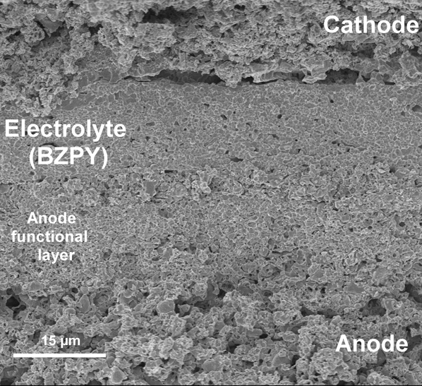
As outlined previously, the main issues related with reducing SOFC operating temperature are the increased electrolyte resistivity and electrode polarization. In addition to improving the electrolyte conduction properties and electrode kinetics, modifying the fuel cell design might also assist in overcoming these drawbacks. Making the anode the supporting structure for SOFC fabrication allows the electrolyte to be implemented as a thin layer, thereby minimizing ohmic loss. Several ceramic processing methods have been proposed to fabricate anode-supported H+-SOFCs. Most of the tested H+-SOFCs on the laboratory scale are fabricated by a co-pressing and co-firing technique,Reference Fabbri, Bi, Pergolesi and Traversa32 which generally allows a minimum electrolyte thickness (capable of preventing reactant cross-over) of ∼15 μm to be supported on a porous anode structure, as shown in Figure 3.Reference Fabbri, Bi, Tanaka, Pergolesi and Traversa33
Scanning electron microscope image of the fractured cross-section of an anode-supported H+-SOFC (solid-oxide fuel cell). Four layers are clearly visible: the supporting anode, the anode functional layer, the electrolyte (BaZr0.7Pr0.1Y0.2O3–δ), and the composite cathode. Reproduced with permission from Reference 33. © 2011 Wiley.
The development of anode-supported H+-SOFCs based on doped-BaZrO3 electrolytes is complicated by the poor sinterability of this material. This problem has been addressed following different approaches; by using doping elements able to favor the sinterability (i.e., BaZr0.7Pr0.1Y0.3O3–δ,Reference Fabbri, Bi, Rupp, Pergolesi and Traversa34 BaZr0.7Sn0.1Y0.3O3–δ,Reference Sun, Liu and Liu35 BaZr0.8/0.7In0.2/0.3O3–δReference Sun, Zhu, Shi and Liu36,Reference Bi, Fabbri, Sun and Traversa37 ), by the addition of sintering aids,Reference Sun, Fabbri, Bi and Traversa38–Reference Tong, Clark, Hoban and O’Hayre40 or by using anodes able to promote electrolyte sinterability.Reference Bi, Fabbri, Sun and Traversa41,Reference Bi, Fabbri and Traversa42 Several H+-SOFCs have also been developed using a solid solution of barium zirconate and barium cerate (e.g., BaCe0.7Zr0.1Y0.2O3–δ) as an electrolyte.Reference Fabbri, Bi, Pergolesi and Traversa32 However, it has been recently shown that even by lowering the Ce content down to 50 at.%, the solid solution between barium zirconate and cerate presents severe stability limitations in a wet atmosphere.Reference Slodczyk, Sharp, Upasen, Colomban and Kilner43
The highest power density outputs for H+-SOFCs using chemically stable BaZrO3-based electrolytes are around 250 mW cm–2 at 600°CReference Fabbri, Bi, Pergolesi and Traversa32,Reference Sun, Liu and Liu35 —still not sufficiently competitive with the performance of SOFCs based on oxygen-ion conducting electrolytes.Reference Wachsman and Lee1
The performance of fuel cells based on Ca-doped LaNbO4 as the electrolyte is even lower, mainly ascribed to the poor kinetics of several tested cathode materialsReference Magraso, Fontaine, Bredesen, Haugsrud and Norby13 and the lower protonic conductivity of this material compared to the best perovskites. In addition, the fabrication of a complete cell using LaNbO4 avoiding detrimental phase segregation is very challenging. Unless these remaining issues are addressed, LaNbO4 will not be the ultimate electrolyte choice for fuel cell applications. Concerning the LWO electrolyte, tailor-made anodes and cathodes with ASRs ∼0.3–0.5 Ω cm2 have been proposed,Reference Solis, Vert, Balaguer, Escolastico, Roitsch and Serra31,Reference Balaguer, Solis, Bozza, Bonanos and Serra44,Reference Quarez, Oumellal and Joubert45 but electrode-supported fuel cells have not yet been tested.
Using different fuel cell designs, promising results for H+-SOFCs have been obtained by fabricating polycrystalline BZY freestanding membranes on Si chips by thin-film deposition and microfabrication technologies. A peak power density output of 186 mW cm–2 at 450°C has been achieved.Reference Kim, Gur, Kang, Jung, Sinclair and Prinz46 These results, coupled with the high conductivity of BZY epitaxial thin films with reduced grain boundary regions, open new possibilities for the development of miniaturized H+-SOFCs.
Summary and perspectives
HTPC-sintered polycrystalline pellets, as well as highly ordered thin films, have shown conductivity values in the same range or even larger than those of the best performing (and chemically stable) oxygen-ion conductors at low temperatures. Moreover, composite cathode materials, mixed protonic and electronic conductors, specifically designed for HTPC electrolytes, have been developed showing comparable performance as the typical cathodes used for oxygen-ion conductors.
In spite of the good performance of the individual cell components, the power density output reported so far for H+-SOFCs is significantly lower compared to SOFCs based on oxygen-ion conductors. The reason for this relatively limited performance is not clear, but it might be due to poorer electrode kinetics, especially in the cathode. It must be highlighted here that research and development on H+-SOFCs is still relatively limited. Improved cell design and microstructural optimization may render the key solution. The good performance of the individual cell components holds the promise of obtaining larger power density output, and clearly indicates the need for more scientific and technological efforts for full exploitation of the potential of HTPCs.
Acknowledgments
E.F. gratefully acknowledges the Swiss National Foundation (SNF) within the Ambizione project for financial support. A.M. would like to acknowledge continuous funding from the Research Council of Norway and the Nordic Top-Level Research Initiative. D.P. would like to acknowledge for financial support the European Community’s Seventh Framework Programme (FP7/2007–2013) under Grant No. 290605 (COFUND: PSI-FELLOW).