I. INTRODUCTION
The repair of larger bone defects due to trauma and arthritis, and associated with surgical procedures (i.e., tumor and bone infection resection or craniotomy), has been a major clinical problem.Reference Tang, Tare, Yang, Williams, Ou and Oreffo1–Reference Gao, Deng, Feng, Mao, Li, Yang, Deng, Cao, Shuai and Peng3 When bone is damaged, mediators including osteoblasts, osteoclasts, and progenitor cells go through a sequence of events to repair the damage.Reference Mediero, Wilder, Perez-Aso and Cronstein4,Reference Semyari, Rajipour, Sabetkish, Sabetkish, Abbas and Kajbafzadeh5 This inherent ability of bone regeneration has been harnessed and enhanced with the use of bone grafts.Reference Shadjou and Hasanzadeh6–Reference Heller, Bauer, Goetze, Gielisch, Ozbolat, Moncal, Rizk, Seitz, Gelinsky, Schroder, Wang, Muller and Al-Nawas9 Bone grafts have been traditionally performed through bone transplants. However, multiple problems, including infections and pathogenic immune responses in the case of allografts, and donor site morbidity and limited amounts of usable bone tissue for autografts, limit their effective use.Reference Vural, Odabas, Korkusuz, Saglam, Bilgic, Cavusoglu, Piskin and Vargel10–Reference Gredes, Kunath, Gedrange and Kunert-Keil13
The above-mentioned obstacles have prompted significant need for a safer and more reliable method that circumvents the problems with current therapeutic strategies for bone defects. The use of three-dimensional (3D) printing in bone tissue engineering holds promise as a methodology that aids in bone regrowth by not only mimicking the properties of natural bone but also providing tissue constructs for new bone formation and growth guidance.Reference Cox, Thornby, Gibbons, Williams and Mallick14–Reference Pati, Song, Rijal, Jang, Kim and Cho19 For successful bone regeneration, constructs must be fully interconnected, able to degrade in a controlled manner, enhance the diffusion of oxygen and transportation of nutrients, and provide cells with the necessary attachment, proliferation, and tissue formation factors.Reference Bose, Vahabzadeh and Bandyopadhyay20 In many load-bearing clinical applications, structural integrity is highly essential for successful tissue regeneration process. Compared to traditional biofabrication techniques (i.e., melt blending, particulate leaching, and molding), 3D printing is a promising method to fabricate tissue constructs, which provides a high degree of control on construct design parameters that are essential for bone tissue regeneration such as pore size, interconnectivity, filament diameter, degradation rate, and mechanical properties.Reference Hospodiuk, Moncal, Dey, Ozbolat, Ovsianikov, Yoo and Mironov21 In that aspect, 3D printing allows optimal tissue constructs to be printed that include all of these intricacies necessary for utilization in successful treatment of bone defects.Reference Tsang and Bhatia22
Polycaprolactone (PCL) is one of the most commonly used synthetic biomaterials for 3D printing of bone tissue constructs due to its printability, quick solidification after extrusion, biocompatibility, and mechanical strength.Reference Heo, Kim, Wei, Kim, Hyun, Yun, Kim, Yoon, Kim, Park, Shin and Shin23 PCL has also been used in FDA approved devices.Reference Ulery, Nair and Laurencin24 However, PCL constructs have slow degradation rates after implantation, which can adversely affect bone regeneration if the synthetic constructs remain intact for extended periods.Reference Kwon, Kwon, Park, Park, Jang, Yin, Yun, Kim, Min, Lee, Kim and Kim25 In addition, PCL has limited biofunctionality in enhancing bone regeneration. To overcome these limitations, we developed a functionalized composite ink composed of PCL, poly(D,L-lactide-co-glycolide) (PLGA), and hydroxyapatite particles (HAps) wherein PLGA has a higher degradation rateReference Lee, Kim, Heo, Kwon and Choi26 and HAp is considered osteoconductive.Reference Wei and Ma27 Bone is a complex structure composed of an inorganic mineral structure, hydroxyapatite and an organic protein, collagen, in which hydroxyapatite plays an important role in mechanical properties. Here, we demonstrate that 3D-printed constructs made of PCL/PLGA/HAp ink could be used as a replacement for widely used PCL inks for bone tissue repair. Previously, PCL/PLGA/HAps have been combined to fabricate constructs using melt-blending and particle-leaching techniquesReference Li, Zhang, Zhang, Xie, Zhao and Zhang28; however, 3D printing of constructs utilizing these three components has not previously been performed.
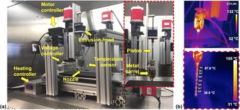
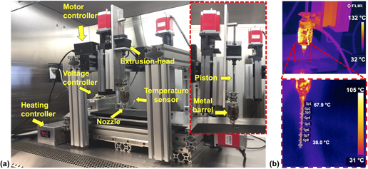
To print 3D composite constructs, we developed a new custom-designed extrusion tool (see Fig. 1). We studied the printability, surface, and mechanical properties of the composite ink and performed in vitro and in vivo studies to determine the effectiveness of composite constructs on bone regeneration. We compared the results with respect to the PCL constructs and showed that composite ink had greater mechanical, biological, and osteoconductive properties and also yielded better bone formation and vascularization, demonstrating its potential in 3D printing for bone tissue repair.
(a) In-house developed mechanical extrusion system mounted to the MABPReference Ozbolat, Chen and Yu29 and its components; (b) thermal images (during extrusion deposition) taken by using a FLIR thermal camera showing typical temperature ranges for PCL printing.

II. MATERIALS AND METHODS
A. Development of the 3D printing setup
A mechanical extrusion system was developed in-house to extrude PCL and composite ink through a metal nozzle (McMaster-Carr, Elmhurst, IL). The mechanical extruder unit was mounted on the z-axis of one of the arms of the home-made Multi-Arm Bioprinter (MABP) (The University of Iowa, Iowa City, Iowa) developed in our previous work [Fig. 1(a)].Reference Ozbolat, Chen and Yu29 A metal barrel was mounted to the bottom part of the z-axis column and aligned within the same horizontal plane as the mechanical dispenser. A piston was connected to the lead of the mechanical dispenser via a custom-made shaft. A metal nozzle band heater (McMaster-Carr) was wrapped around the metal syringe. A CN7533 (Omega Engineering, Stamford, CT) advanced temperature/process controller was used to maintain the temperature at the end of the metal nozzle tip via a K-type thermocouple feedback sensor (Omega Engineering) that was placed at the lower end of the metal barrel.
B. Materials
PCL was purchased from Scientific Polymer Products, Inc. (Ontario, NY) in pellet form (Mw 70,000). PLGA (50:50) (Resomer RG 503) was purchased from Evonik Ind. (Darmstadt, Germany) (inherent viscosity 0.32–0.44 dL/g). HAps (nanoXIM-HAp202, Fluidinova, Moreira da Maia, Portugal) were acquired in powder form with an average particle size of 5 µm.
C. Preparation of composite ink solution
Composite ink solution composed of PCL, PLGA, and HAp were prepared with a ratio of 4.5:4.5:1. A total of 5.4 g PCL and PLGA pellets were fully dissolved in 54 mL chloroform (Fisher Scientific, Pittsburg, PA)/100 mg dry powder under vigorous stirring. HAp was then added and the solution was stirred for 30 min. The solution was then subjected to ultrasonication (Model 3000 ultra-homogenizer) (Biologics Inc., Cary, NC) for 10 min at 50% power and 50% pulse. The homogenized solution was then solvent cast as a thin layer on Teflon dishes (Fisher Scientific) and placed within a chemical hood for evaporation. Petri dishes were subsequently placed within an Isotemp vacuum oven (Model 282A) (Fisher Scientific) at 37 °C under vacuum (1.5 in Hg) overnight to fully evaporate the chloroform. Thereafter, thin composite films were removed from Petri dishes and stored at room temperature.
D. Characterization of the PCL/PLGA/HAp composite ink
To confirm the material characteristics of the composite ink, thermogravimetric analysis (TGA) was performed using SDT Q600 TA instrument (Dallas, TX), at a heating rate of 20 °C per min under an air gas flow rate of 100 cm3/min. Chemical analysis of the functional groups within the materials comprising PCL, PLGA, HAp, and the composite ink was carried out using attenuated total reflectance Fourier transform infrared spectrophotometry (ATR-FTIR) (Bruker Vertex V70 FTIR spectrometer, The Woodlands, TX). ATR-FTIR measurements of 100 scans per sample with a spectral range of 400–4000 cm−1 were taken to comprise FT-IR spectra at a resolution of 0.48 cm−1.
The wide-angle X-ray scattering (WAXS) of crystallinity was performed on a The Xenocs Xeuss 2.0 (Xenocs, France) using microfocus sealed tube (copper) as a beam source (X-ray wave length of 1.54 Å, 50 kV, 0.6 mA) equipped with a Pilatus3 R200K detector. The samples were placed on a sample holder into the sample chamber in vacuum and then the scattering experiments were performed at room temperature and integrated over a tilted circle profile to convert two-dimensional images into one-dimensional scattering data of scattering intensity I(q) (in arbitrary units) versus 2θ (degree). Data collection was performed using nine positions of the detector in virtual detector mode for 60 s per image.
All rheological measurements of PCL and composite inks were performed using a MCR 702 rheometer (Anton Paar, Ashland, VA) with a 25-mm diameter parallel-plate geometry measuring system. For the temperature ramp test, storage modulus (G′) and loss modulus (G″) of PCL and composite inks were monitored as a function of temperature to determine temperature dependency at 1 Hz frequency and a shear strain range of 5 to 1%. Temperature was decreased from 115 °C and 150 °C to 42 °C for PCL and composite inks, respectively, with a constant cooling rate of 2 °C/min. In addition, frequency sweep was carried out to get complex viscosities (|η*|) at a constant strain of 5% in the range of 0.1–628 rad/s under constant temperatures of PCL (65, 75, 85, 95, 105, and 115 °C) and composite (50, 70, 90, 110, 130, and 150 °C) inks.
E. Fabrication of bone tissue constructs
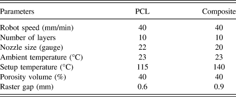
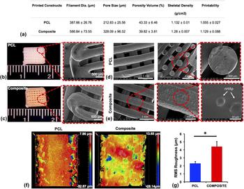
Bone tissue constructs were 3D printed using the MABP [Fig. 1(a)]. Constructs were designed using Mach3 software (Newfangled Solutions LLC, Livermore Falls, Maine) with a lay-down pattern of 0°/90° using PCL and the composite ink. To extrude the inks at a molten state, the heater was set to 115 °C and 140 °C for PCL and composite constructs, respectively. The molten inks were loaded into the preheated metal barrel and subsequently extruded using the custom-designed mechanical extruder [Fig. 1(b)]. The constructs were printed using the parameters listed in Table I. The printability of the constructs was determined based on equations described in our previous work.Reference Ozbolat, Dey, Ayan, Povilianskas, Demirel and Ozbolat30 After printing two layers, the constructs were imaged under an Invitrogen EVOS FL auto cell imaging system (Thermo Fisher Scientific, Waltham, Massachusetts). Images were taken at bright field mode with 4× magnification from four different regions on each construct. Printability data were extracted from an average of five pore measurements per image, with a total of four images per construct, and five printed constructs in total. Pore area and perimeter were calculated using the manufacturer’s software. Filament diameter and pore size were measured using the manufacturer’s software for two layers of PCL and composite constructs. Filament diameter and pore size data were exported a total of 40 filament diameters and 40 pores per construct, examining five printed constructs for each group.
Printing parameters.

F. Characterization of 3D-printed constructs
Interferometric optical profilometry (Zygo NexView 3D, Zygo Corporation, Middlefield, CT) was used to determine the surface roughness. To utilize the surface roughness of individual filaments, PCL and composite constructs were imaged under a 50× Mirau objective with a 0.5× magnifier lens under white light with a scan length of 65 μm. Using Zygo Mx’s surface processing software (Zygo Corporation), a data processing sequence that included form remove of cylindrical surface type and threshold of two square pixels were applied to all construct measurements to decrease the impact of filament curvature on the measured values and reduce noise, respectively. Root mean square (RMS) roughness was calculated for each measurement to assess the variability in height for each construct. Three constructs of each composition were analyzed, with a total of five measurements for each group.
G. Mechanical testing
Compressive mechanical properties of 10-layer printed PCL and composite constructs were examined using an Instron 5966 mechanical tester (Instron, Norwood, Massachusetts) equipped with a 10 kN load cell and with a crosshead speed of 50 mm/min. The samples were oriented on their x–y plane on the plate and compressed to 50% strain. Results were averaged from five samples.
H. In vitro accelerated degradation study
In vitro accelerated degradation assay was performed using dual-layer printed PCL and composite constructs total of three constructs for each time point per group based on the previous work.Reference Yang, Webb, Pickerill, Hageman and Ameer31 Briefly, samples were placed in 0.1 M sodium hydroxide (NaOH) (Alfa Aesar, Haverhill, MA) solution to observe relative degradation at 37 °C for every 12 h up to 72 h. Final dry mass was compared to initial dry mass to determine mass loss percentage.
I. Skeletal density and porosity volume analysis
Ten-layer PCL and composite constructs were used to measure the construct density using an AccuPyc II 1340 Series pycnometer (Micromeritics, Norcross, Georgia). After measuring their mass, each sample was first placed in a standard sample cup and then placed inside a chamber. Purge fill pressure was set at 134.45 MPa with an end equilibration rate of 34.5 Pa/min. Sample density (D samp) and sample volume (V samp) were calculated using the following equations:
 $${V_{{\rm{samp}}}} = {V_{{\rm{cel}}}} - {V_{{\rm{exp}}}} \times \left( {{{{P_1}} \over {{P_2}}} - 1} \right)\quad ,$$
 $${D_{{\rm{samp}}}} = {{{M_{{\rm{samp}}}}} \over {{V_{{\rm{sanp}}}}}}\quad ,$$
where V cel is the sample chamber volume, V exp is the expansion chamber volume, P 1 is the gauge pressure after fill, P 2 is the gauge pressure after expansion, and M samp is the sample mass. Data were exported from an average of five cycles per construct with a total of five printed constructs per group. The porosity volume (PV) of printed constructs was calculated using Eq. (3) and the bulk volume (BV) of the printed constructs was measured by multiplying height, depth, and width of each construct. Dimensional measurements were taken using a digital caliper and an average of five measurements in each dimension was taken for each construct. The actual volume (AV) of printed constructs was measured using an AccuPyc II 1340 Series pycnometer from an average of five cycles per construct with a total of six constructs per group. Thereafter, the porosity was calculated using the ratio of AV over the BV.
 $${\rm{PV}}(\% ) = \left( {1 - {{{\rm{AV}}} \over {{\rm{BV}}}}} \right) \times 100\quad .$$
J. Cell culture study
Primary culture rat bone marrow stem cells (rBMSCs) were used to study cell proliferation and osteogenic differentiation. For isolation of rBMSCs, inbred 12-week-old male Fisher white rats (F344/DuCrl, 250 g) were obtained from Envigo (Frederick, MD) and euthanized using CO2 according to the protocol approved by The Institutional Animal Care and Use Committee (IACUC) at the Pennsylvania State University. Thereafter, rBMSCs were isolated from femurs and tibias as previously described.Reference Zhang and Chan32 Isolated rBMSCs were plated on 6-well plastic cell culture plates in αMEM containing 10% fetal bovine serum (FBS) (Thermo Fisher Scientific), 2 mM L-glutamine (Thermo Fisher Scientific), 100 u/ml penicillin (Sigma-Aldrich, St. Louis, Missouri), and 100 µg/mL streptomycin (Sigma-Aldrich). The cultures were incubated at 37 °C in a humidified 5% CO2 incubator and media was changed every three days. When primary cultures became nearly confluent, they were treated with 0.25% Trypsin (Thermo Fisher Scientific) and cultured in a 75 cm2 flask. For the in vitro study, dual-layer PCL and composite constructs were printed to facilitate microscopy. The constructs were then sterilized using an Anprolene gas sterilizer (AN74iX, Anderson Sterilizers, Haw River, NC) with ethylene oxide. After sterilization, 1000 rBMSCs/mm2 were seeded on top of the PCL and composite constructs. After cell seeding, the constructs were placed in a 24-well plate, 1 mL of differentiation media was added to each well, and the constructs were incubated for further studies. Differentiation media consisted of α-MEM, 10% FBS, 10 mM β-glycerophosphate disodium salt hydrate (Sigma-Aldrich), 50 µg/mL ascorbic acid (Sigma-Aldrich), 100 U/mL penicillin 100 µg/mL streptomycin (Sigma-Aldrich), and 10−7 M dexamethasone (Sigma-Aldrich).
K. Scanning electron microscopy imaging
rBMSC-seeded samples at 28 days were fixed using 4% paraformaldehyde at 4 °C overnight. After fixation, the samples were washed with DPBS three times for 15 min and then dehydrated in graded ethanol solutions. Thereafter, the samples were placed in a critical-point dryer (Leica EM CPD3000, Leica Microsystems, Wetzlar, Germany). The samples were subsequently iridium sputter-coated (Emitech K575X, Emitech Ltd., Ashford, Kent, England) for 40 s, and placed into a scanning electron microscopy (SEM) chamber (FEI Nova NanoSEM 630 FESEM, Hillsboro, Oregon) and imaged at an accelerating voltage of 3.0–5.0 keV.
L. Cell proliferation assay
Using cell counting kit-8 (CCK-8) (Dojindo Molecular Technologies, Rockville, MD), cell proliferation assay was performed based on manufacturer’s instruction on Days 1, 4, and 7. At each predetermined time point, five constructs from each group were transferred to a 24-well plate and rinsed with DPBS and then 300 µL of fresh medium containing CCK-8 was pipetted into each well followed by incubation at 37 °C for 2 h. After incubation, the intensity was measured using a microplate scanning spectrophotometer (Bio-Tek PowerWave ×340, Bio-Tek Instruments Inc., Winooski, VT) at 450 nm excitation. To determine the cell numbers, six points of serial dilution of rBMSCs were made ranging from 0 to 50 × 105 cells; each cell concentration was suspended in 300 µL of media and treated the same as the construct samples for the proliferation assay. Cell numbers were calculated from the generated standard curve.
M. Quantitative real-time polymerase chain reaction
To analyze the multiple osteogenesis-related gene expression profiles including alkaline phosphatase (ALP), osteocalcin (OCN), and runt-related transcription factor 2 (RUNX2), quantitative real-time polymerase chain reaction (RT-PCR) was performed after 14 and 21 days of osteogenic differentiation. At these time points, the total RNA of rBMSCs cultured on PCL and composite constructs was isolated by using RNeasy Mini Kit (Qiagen, Germantown, Maryland) according to the manufacturer’s instructions. The primers of the measured mRNA genes are included in Table II. RT-PCR was analyzed using the Power SYBR™ Green Master Mix (Thermo Fisher Science). Threshold cycle values were calculated using a comparative cycle threshold method. All results were normalized by glyceraldehyde 3-phosphate dehydrogenase (GAPDH), and the ratio of the normalized fold change was calculated using rBMSCs cultured in standard cell culture conditions as 1-fold.
Primers of the measured mRNA for RT-PCR.

N. Immunocytochemistry
To quantify and trace the differentiation of rBMSCs to an osteogenic lineage, the constructs were stained with RUNX2 and bone sialoprotein (BSP). On Day 28, the constructs seeded with rBMSCs were rinsed twice with PBS, then fixed in 4% paraformaldehyde overnight at 4 °C. The following day, the constructs were rinsed three times with PBS. Cells were permeabilized in a solution of 0.1% Triton (Sigma-Aldrich) in DPBS for 15 min at room temperature on a shaking platform. A blocking solution of 10% normal goat serum (NGS) (Sigma-Aldrich) in DPBS was applied for 1 h at room temperature. Primary antibodies for RUNX2 and BSP were purchased from Abcam (Cambridge, Massachusetts). The mouse monoclonal antibody to RUNX2 was diluted to a concentration of 10 µg/mL in 1% NGS in DPBS; the rabbit polyclonal antibody to BSP was diluted 1:200 in the same diluent. The constructs were placed in 300 µL of primary antibody and incubated at 4 °C overnight. The next day, the constructs were rinsed three times with DPBS for 15 min. Secondary detection antibodies (Life Technologies, Waltham, MA) consisting of Alexa Fluor 488 goat antimouse IgG for RUNX2 (green fluorophore) and Alexa Fluor 568 goat antirabbit IgG for BSP (red fluorophore) were diluted 1:200 in DPBS 1% NGS and applied to the constructs for 2 h at room temperature. The constructs were washed three times with DPBS for 15 min each and imaged on an AxioZoom V16 (Zeiss, Oberkochen, Germany) fluorescent microscope.
O. Implantation of printed constructs into rat calvarial defects
A total of five inbred 12-week-old male Fischer 344 white rats were obtained from Envigo (Frederick, Maryland), housed, and cared in the animal facility. The surgical procedures were approved and performed according to the guidelines established by IACUC at the Pennsylvania State University. Rats were anesthetized with an intraperitoneal injection of ketamine (Midwest Veterinary, Lakeville, Minnesota)/xylazine (LLOYD Inc., Shenandoah, Iowa) at a dose of 100 mg/kg and 10 mg/kg, respectively. A sagittal incision (∼2 cm long) was made to expose the calvaria. Two critical size calvarial defects were drilled into the parietal bone on each side of the rat skull using a trephine bit, taking care to keep the dura mater intact. 5-mm circular plugs were punched using a steel hole punch tool through dual-layer PCL and composite constructs to create circular implants. PCL and composite constructs were implanted into the defects and empty defects were performed as a control group. After implantation, the periosteum and skin were closed with simple interrupted 5-0 monocryl (Ethicon Inc., Somerville, New Jersey) and 4-0 vicryl (Ethicon Inc.) sutures, respectively. A dose of buprenorphine (0.015 mg/kg) was administered post-surgery and an additional application of bupivacaine was applied topically. After eight weeks, the rats were euthanized and the calvaria tissues were fixed in 4% paraformaldehyde.
P. Microcomputed tomography measurement
A microcomputed tomography (µCT) scanner (VivaCT 40, Scanco Medical, Switzerland) was used with 17.5 µm voxel resolution, 70 kV energy, 114 µA intensity, 35.8 mm diameter field-of-view, and 200 ms integration time to evaluate bone regeneration. Calvarial explants were placed inside the µCT scanner and bony segments were scanned. After adjusting the angle of rotation, sample alignment, and reconstructed two-dimensional (2D) images, µCT scanning was performed for 30–60 min per explant scanned. DICOM files were processed in Avizo software (FEI Company, Hillsboro, Oregon). A hydroxyapatite (HA) phantom (Micro-CT HA, QRM, Germany) was included in each scan and used to generate a standard curve to convert Hounsfield units to mgHA/ccm. Images were processed with a Gaussian smoothing filter (sigma 0.9) to reduce noise and a threshold of 300 mgHA/ccm was used to remove unmineralized tissue from analysis. Cylindrical volumes-of-interest with 4 mm diameter and 0.7 mm thickness (average calvarial bone thickness) were then aligned in a 3D space with the centerline of each defect, and bone volume and bone volume fraction were calculated for voxels within the cylinders.
Q. Histological analysis
After µCT scanning, explants were dissected from the soft tissue (ST), rinsed with DPBS, and fixed with 4% paraformaldehyde for two days. Thereafter, the samples were rinsed with DPBS and added with 0.5 M ethylenediaminetetraacetic acid (EDTA) disodium salt (Research Products International, Mt. Prospect, IL) solution to start the decalcification process. Skulls were then decalcified approximately six weeks later, and the samples were embedded in cyromatrix (ThermoFisher Scientific) embedding resin and sectioned using a Leica CM1950 cryostat (Leica Biosystems, Wetzlar, Germany) at −20 °C with 20 μm thickness and placed on microslides (VWR). Next, the samples were placed on the Haemotoxylin and Eosin (H&E) automated staining platform (Leica Auto Stainer XL, Leica Biosystems) without applying any heat during the staining process and imaged using an EVOS FL auto cell imaging system under bright field with 4× magnification. Immunohistochemistry staining for platelet endothelial cell adhesion molecule (PECAM-1) was then applied to determine vascularization on the sectioned histological samples, as described above and imaged using an Olympus BX61 microscope (Olympus Corporation, Tokyo, Japan). 100× images were taken using Keyence BZ-9000 (Keyence Corporation of America, Elmwood Park, NJ) fluorescence microscopy via an oil immersion lens for high quality imaging.
R. Statistical analysis
All data are presented as the mean ± standard deviation unless stated otherwise and were analyzed using one-way analysis of variance to test for significance when comparing the data. Post hoc Tukey’s multiple comparison test was used to determine the individual differences among the groups. To compare two groups (in mechanical and surface roughness analysis), data were analyzed using Student’s t-test with a 95% confidence interval. Differences were considered significant at P < 0.05 (*), P < 0.01 (**), and P < 0.001 (***). All statistical analyses were performed by Minitab 17.3 (Minitab Inc., State College, PA).
III. RESULTS
A. Characterization of the PCL/PLGA/HAp composite ink
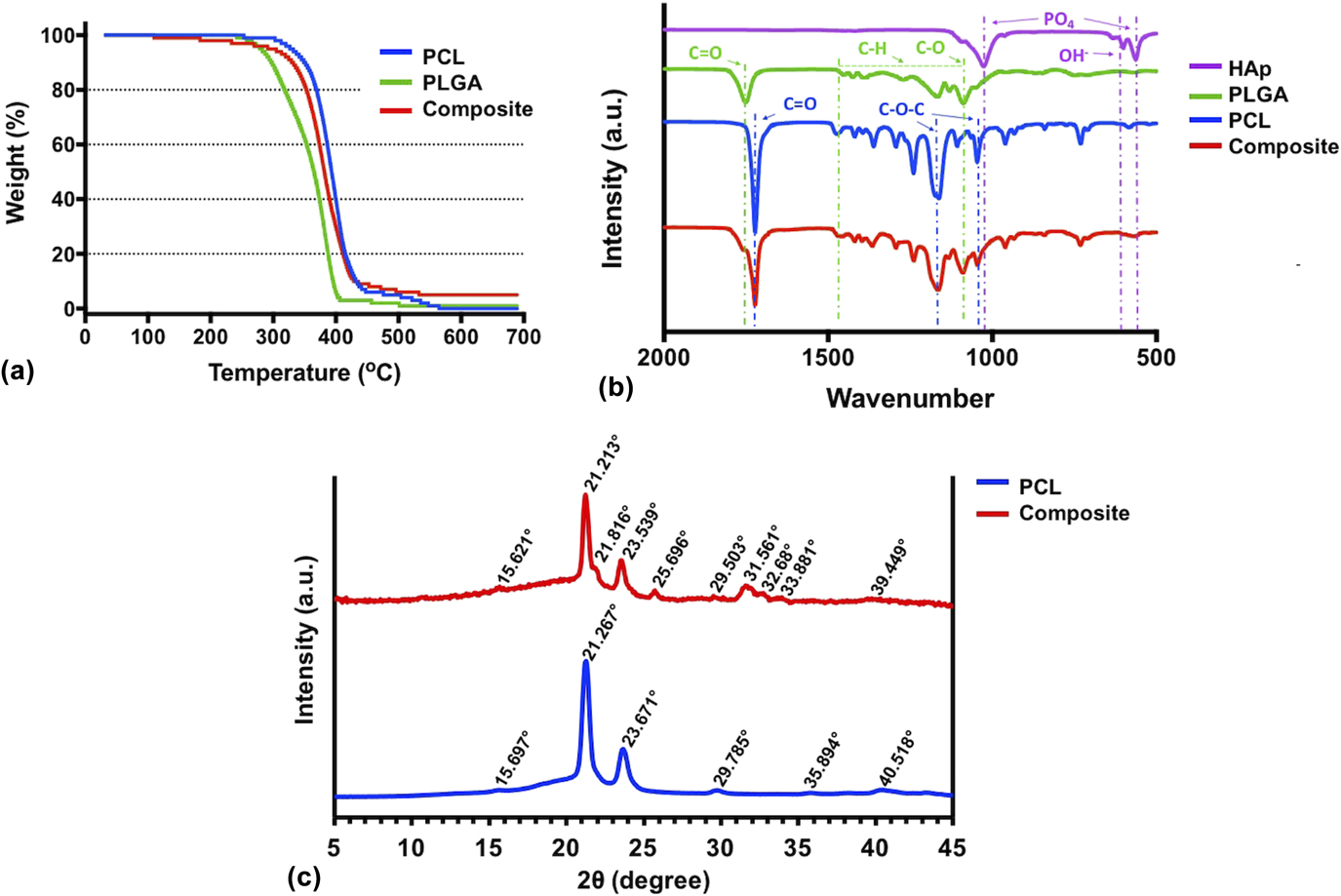
The composite ink was prepared by the solvent evaporation method, and its material characteristic was confirmed by TGA and ATR-FTIR spectroscopy. As shown in Fig. 2(a), PCL had the highest decomposition temperature, where the greatest amount of weight loss took place at 412 °C followed by 100% weight loss around 600 °C. PLGA reached its maximum weight loss at 378 °C, while 100% weight loss was observed around 500 °C. The composite ink experienced the highest weight loss at 378 °C, where only 10% of it remained. The composite ink did not exhibit 100% weight loss within the temperature range between 30 and 700 °C due to the high melting temperature of HAp.Reference Lee, Kim, Heo, Kwon and Choi26 10% of the composite ink remained at 420 °C, which was equivalent to the initial weight percentage of HAp in the composite ink. Overall, a 5% weight loss was observed during the printing process within the temperature range of 30–300 °C, which did not affect the overall concentration of the composite ink during extrusion deposition. The ATR-FTIR spectra of PCL, PLGA, HA, and the composite ink contained major peaks from each component that were labeled at appropriate wave numbers to show inclusion, if any, that exists in the composite ink [Fig. 2(b)]. Many absorption bands were found in the individual components of the composite ink, which were also found within the spectrum of the composite ink. The absorption band at 1722 cm−1 is a characteristic of the –C=O stretching vibrations of the ester carbonyl group, and absorption bands at 1238 cm−1 and 1160 cm−1 are characteristics of C–O–C asymmetric and symmetric stretching, respectively, for PCL.Reference Abderrahim, Abderrahman, Mohamed, Fatima, Abdesselam and Krim33 The absorption band at 1250 cm−1 denotes C–O stretching of the carboxylic acid group and the band at 1773 cm−1 is a characteristic of carbonyl –C=O stretching within PLGA. Also, the absorption bands ranging from 1300 to 1500 cm−1 are characteristics of C–H bending of methyl and glycolic acid groups for PLGA.Reference Zhang, Liu, Luo, Chen, Li, Yuan, Wang and Huang34 Characteristic peaks for HA were identified between 900 and 1200 cm−1 and 500–620 cm−1, which are related to the internal vibrations of the PO4 tetrahedra.Reference Berzina-Cimdina and Borodajenko35 However, the peaks for HA are not easily discerned in the composite ink spectrum.
(a) TGA and (b) ATR-FTIR results of the ink components, (c) WAXS of crystallinity reflections of PCL and composite inks.
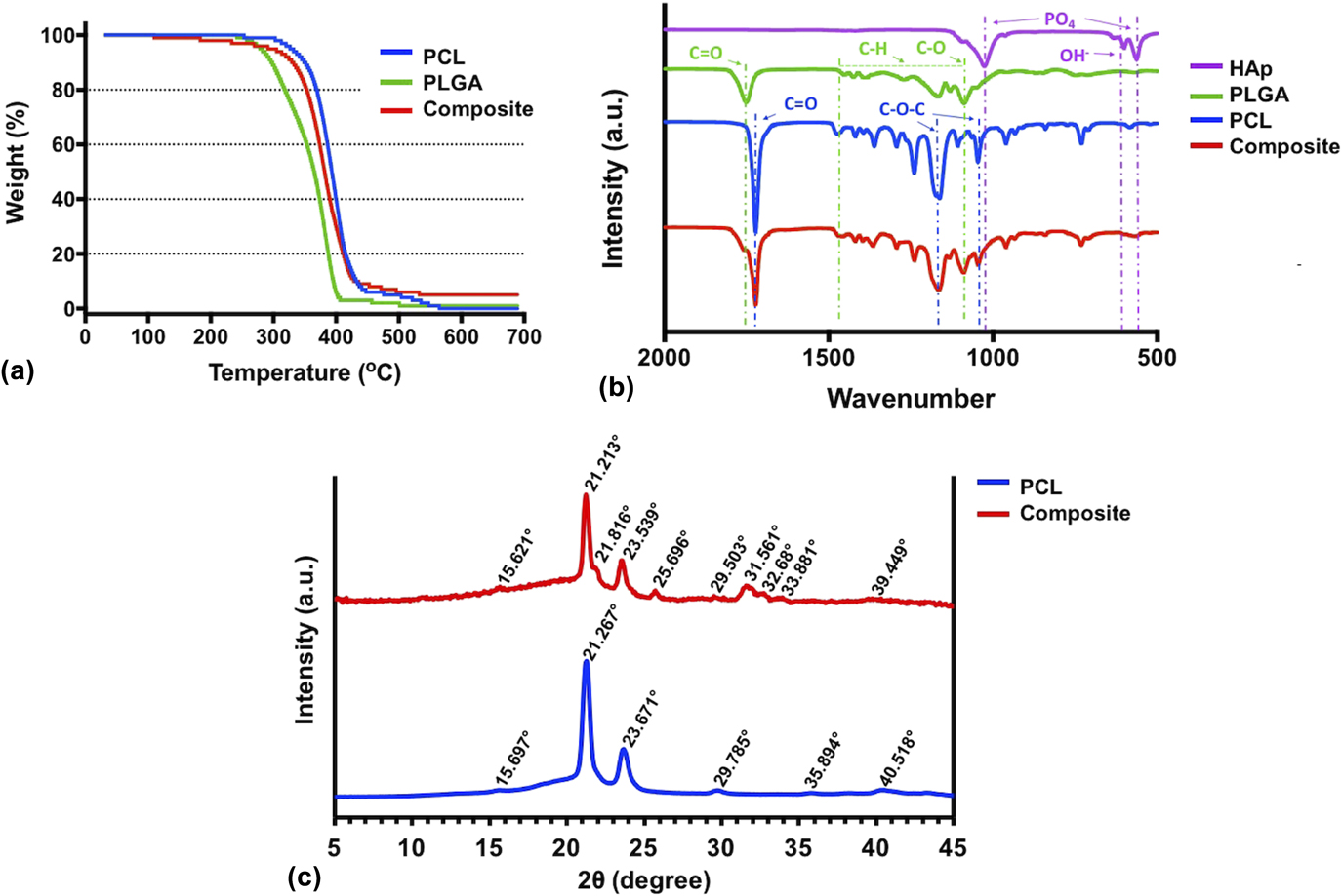
WAXS of crystallinity reflections of PCL and composite inks is demonstrated in Fig. 2(c), where Bragg’s law conditions were satisfiedReference Rhodes36 at the particular angles producing a reflection from the crystal. In the composite material, characteristic peaks from PCL as well as PLGA (ICDD-PDF No. 00-064-1625, polylactic acid and ICDD-PDF No. 00-024-1758, glycolic acid) and HA (ICDD-PDF No. 00-009-0432) were apparent meaning that crystallinity remained unchanged after the preparation of the composite ink.
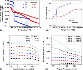
To understand melt properties of PCL and composite inks to evaluate their printability, a rheological measurement study was conducted in certain temperature intervals. Temperature dependency of G′ and G″ in the range of 42–150 °C are presented in Fig. 3(a). Both G′ and G″ increased with cooling of PCL and composite inks, and their crossover points were observed at 57.4 and 44.8 °C, which are melting point of PCL and glass transition temperature of PLGA, respectively.Reference Mu and Feng37 With cooling beyond those temperature points, G′ became higher than G″ so both PCL and composite inks exhibited solid-like viscoelastic material behavior. The melting point of PCL and transition temperature of composite ink [Fig. 3(b)] showed a loss factor as a function of temperature. For PCL, the loss factor showed a rapid decrease between 60 and 56 °C since solidification occurred in this interval. The loss factor of composite decreased with cooling up to 66 °C but increased from 66 to 52 °C. Although G″ was still dominant than G′, its elastic behavior became stronger in this temperature interval. Figures 3(c) and 3(d) represent complex viscosities of PCL and composite melts at six different temperatures. Complex viscosities of both PCL and composite melts decreased as temperature increased. For given testing temperatures, PCL showed shear thinning behavior at high angular frequencies and Newtonian behavior at low frequencies so PCL was flowable even in the long term. On the other hand, although the composite ink behaved like PCL between 90 and 150 °C, it exhibited shear thinning behavior at 50 and 70 °C for all frequencies which means that the samples had yield stress to initiate flow and were more stable in the long term.
Temperature dependency of (a) storage modulus (G′) and loss modulus (G″), (b) loss factor for PCL and composite inks, (c) measured complex viscosities from frequency sweep for PCL and (d) composite inks under a temperature range of 50–150 °C.

B. Characterization of 3D-printed constructs
PCL and composite inks were extrudable using the newly designed mechanical extrusion system. To extrude the PCL ink, the heating control unit was set at 115 °C to adjust the metal needle temperature to ∼60 °C [Fig. 1(b)]. The composite ink required a higher temperature level (∼140 °C) due to the higher melting temperature of PLGA.
PCL constructs demonstrated superior printing results with the printability value closer to “1” meaning that a perfect square shape was attained in the pores of constructs [Fig. 4(a)].Reference Ozbolat, Dey, Ayan, Povilianskas, Demirel and Ozbolat30 On the other hand, composite constructs had a lower printability as the composite ink was not extrudable in a smooth and continuous manner through a 22-gauge nozzle due to its high viscosity; therefore, a 20-gauge nozzle was used to extrude the composite ink. Under the same printing conditions (including extrusion and printing speed), the extruded filaments of the composite ink (∼587 μm) were thicker than the nozzle while the filament diameter in PCL constructs (∼388 μm) was close to the nozzle diameter. To keep the design PV the same (which is 40% in this work), 0.6 and 0.9 mm raster gaps (the distance between adjacent filaments) were considered for the PCL and composite constructs, respectively.
(a) Characterization of printed constructs (data presented ± SD); (b) 3D-printed PCL and (c) composite constructs, (d and e) with their SEM images; (f) surface roughness of PCL and composite ink filaments (g) with corresponding RMS (data presented ± SE Mean).

PCL and composite constructs were printed with a desirable pore size and filament thickness in a highly circular shape [Figs. 4(b) and 4(c)]. SEM images show that both the PCL and composite constructs were shown to have an interconnected porous network with fusion at the filament junctions [Figs. 4(d) and 4(e)]. Assessing the morphology of the constructs reveals that the composite constructs had a greater surface roughness than that of PCL constructs, due to the presence of HAp, which was covered within the filaments [Fig. 4(f)]. Also, filaments of the composite ink exhibited a higher number of pits (small valleys) on the surface. Pits in both PCL and composite constructs varied in depth and morphology. Pits were observed more frequently closer to the edges of filaments for both inks. Composite constructs, however, exhibited more evenly distributed pits compared to those of PCL constructs. Surface roughness was determined as 2.31 ± 0.23 μm for PCL and 4.41 ± 0.64 μm for composite filaments [Fig. 3(g)].
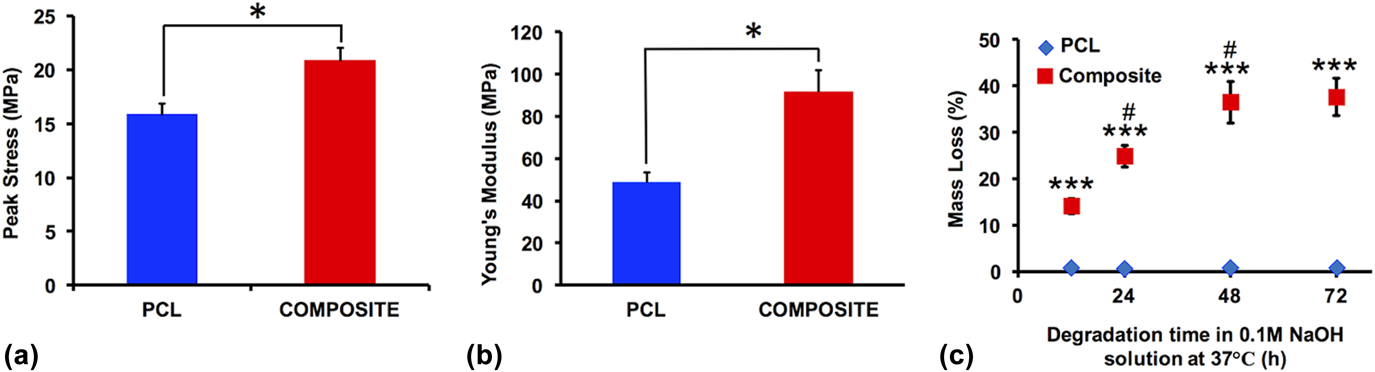
To evaluate the mechanical properties, 3D-printed constructs were compressed to 50% strain. Upon compression, their stiffness increased rapidly and concomitantly with stress and modulus in both groups [Figs. 5(a) and 5(b)]. Ten-layer PCL constructs had a peak stress of 15.9 ± 1.9 MPa while the composite constructs attained a peak stress of 20.9 ± 3.3 MPa (P = 0.022). Young’s modulus of the composite group (91.8 ± 26.12 MPa) was also significantly higher than that of the PCL group (49 ± 8.5 MPa). Overall, the composite constructs were able to withstand a higher compressive load than PCL constructs during deformation.
(a) Ultimate strength and (b) Young’s modulus of 3D-printed PCL and composite constructs; (c) accelerated degradation profile of PCL and composite constructs [# indicates significance (P < 0.01)] with respect to the previous time point in the same group (all data presented ± SD).

The accelerated degradation study showed that composite constructs degraded up to 37 ± 4% whereas PCL constructs only degraded up to 0.73% in 72 h. In 12 h, 14% and 0.69% degradation were observed for composite and PCL constructs, respectively. Over time, PCL construct degradation did not show any noticeable difference, whereas the mass loss in composite constructs increased by 78% and 160% in 24 and 48 h with respect to the mass loss in 12 h, respectively [Fig. 5(c)].
C. Effects of 3D-printed composite constructs on rBMSC proliferation and osteogenic differentiation
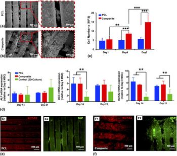
Seeded rBMSCs were able to attach and spread through pores in both PCL [Fig. 6(a)] and composite [Fig. 6(b)] constructs and deposit their extracellular matrix (ECM) over time. There were more clustered cells on composite constructs than PCL counterparts. A baseline number of cells were established on the day after seeding the rBMSCs on respective constructs. On Days 1, 4, and 7, proliferation of rBMSCs seeded on the PCL and composite constructs was assessed [Fig. 6(c)]. The initially attached cell numbers were averaged at 4770 and 5457 cells per construct for PCL and composite constructs, respectively. The cell numbers increased to 5010 and 8604 at Day 4; and 5570 and 14,876 at Day 7 for PCL and composite constructs, respectively.
rBMSC-seeded (a) PCL and (b) composite constructs on Day 28; (c) proliferation of seeded rBMSCs on PCL and composite constructs over time; (d) gene expression of ALP (left), OCN (middle), and RUNX2 (right) determined with RT-PCR; immunocytochemistry staining (RUNX2 and BSP) of seeded cells on (e) PCL and (f) composite constructs on Day 28 (all data presented ± SD).
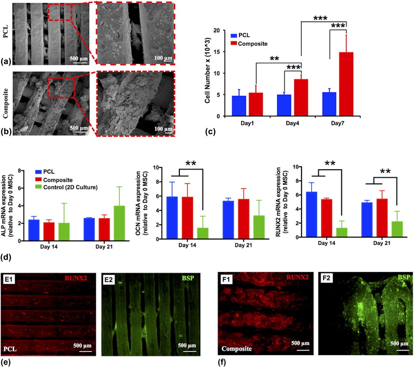
Osteogenic differentiation was studied by analyzing the mRNA levels of ALP, OCN, and RUNX2 profiles of rBMSCs through RT-PCR [Fig. 6(d)]. The average fold change in ALP expression [Fig. 6(d), left] increased from 2.36-fold to 2.54-fold for PCL and 2.05- to 2.53-fold for composite constructs from Day 14–21. OCN expression [Fig. 6(d), middle] for both PCL and composite constructs remained similar at Days 14 and 21; however, both of them were significantly higher than that of the control group. RUNX2 expression [Fig. 6(d), right], which determines differentiation of rBMSCs to preosteoblast, was decreased from 6.38 to 4.87-fold for PCL and increased from 5.34 to 5.4-fold for composite constructs from Day 14 to 21.
Immunocytochemistry staining displayed that the composite constructs expressed stronger intensity of RUNX2 staining compared to PCL constructs. Mineral deposition of bone ECM at Day 28 was determined by immunocytochemistry of constructs with BSP, which is a later time osteogenic differentiation specific marker. Composite constructs displayed a higher amount of bone mineral deposition compared to PCL constructs in a four-week time frame [Figs. 6(e) and 6(f)].
D. Effects of 3D-printed constructs on bone regeneration in critical size rat calvarial defects
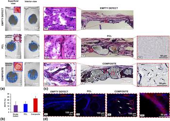
µCT scanning results showed that composite constructs were able to support bone regeneration over time by providing a higher degree of newly formed mineralized bone tissue compared to PCL constructs and empty defects. PCL constructs yielded limited new bone formation, while most bone regeneration occurred at the edges of the defect [Fig. 7(a)]. The highest defect bridging was observed in composite constructs, where bone regeneration was also noticed along the filaments. BV/tissue volume (TV) ratio was examined using a defect size of 4 mm instead of 5 mm to eliminate the possible inclusion of native bone (NB) in our calculations. As shown in Fig. 7(b), µCT scanning results of the implanted constructs resulted in the BV/TV average ratio of 11.5 ± 5.7% for empty defects, 13.7 ± 4% for PCL constructs, and 22.4 ± 4% for composite constructs, which yielded nearly 2-fold bone regeneration compared to the empty defects while PCL constructs and empty defects yielded a similar BV/TV ratio.
(a) µCT scan results showing bone tissue regeneration at eight weeks after implantation, (b) BV/TV (%) results, (c) H&E, and (d) CD31 staining of sectioned bone tissue samples for empty defect, PCL and composite constructs (n = 3, all data presented ± SE mean). (NB indicates NB, RB indicates RB, and ST indicates ST. Black arrows indicate deposition of ECM inside the composite filament. White arrows indicate possible vascularization.)
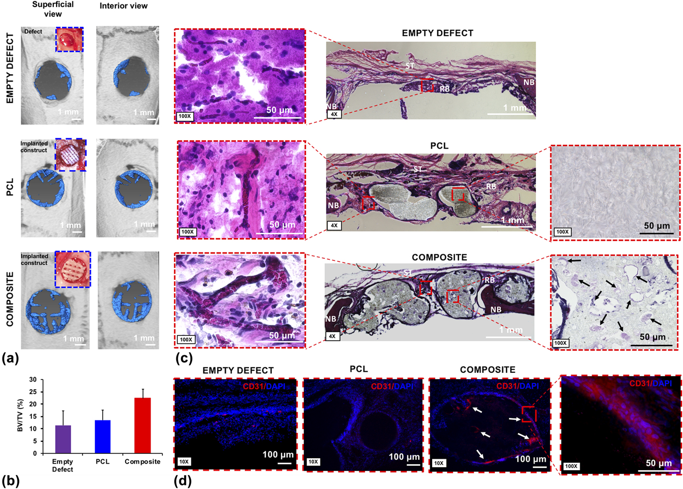
H&E staining demonstrates the general view of sectioned histological skull samples for empty defects, and implanted PCL and composite constructs [Fig. 7(c)]. After the staining process, NB was stained in a darker color compared to the regenerated bone (RB). On the other hand, ST was displayed in pink. More bone regeneration was observed in the pores of the composite constructs, whereas considerable ST formation was observed in empty and PCL construct-implanted defects. In addition, the composite constructs displayed a higher degree of degradation along with some mineralization inside the filaments while PCL constructs did not exhibit noticeable degradation. H&E staining also demonstrates the presence of blood vessels (including branched vasculatures) in the composite construct-implanted defects while no formally organized blood vessels were observed in other groups. In addition, red blood cells were aligned within the newly formed capillaries in the regenerated tissue inside the composite constructs. CD31 staining also confirms that more circular and tubular features were observed in composite constructs [see white arrows in Fig. 7(d)] demonstrating vascularization in newly regenerated tissue.
IV. DISCUSSION
In bone tissue engineering, ideal constructs should possess a 3D structure providing osteoconductive, osteoinductive, or osteogenic substrate features.Reference Cox, Thornby, Gibbons, Williams and Mallick14 In terms of the construct design, the emphasis has been placed on properties including pore size, controlled degradation behavior over time, the ability to have substantial integration with NB at the defect site, and desirable mechanical properties.Reference Velasco, Narvaez-Tovar and Garzon-Alvarado38 It is well known that 3D printing is an effective method to control construct architecture with such desired properties.Reference Heller, Bauer, Goetze, Gielisch, Ozbolat, Moncal, Rizk, Seitz, Gelinsky, Schroder, Wang, Muller and Al-Nawas9,Reference Ozbolat and Hospodiuk39,Reference Ozbolat, Moncal and Gudapati40
In our study, TGA results demonstrated that there were no significant changes in the composition of inks during the printing process demonstrating that inks were thermally stable within the extrusion temperature range. ATR-FTIR data showed that the combination of PLGA, PCL, and HAp did not form any critical new bonds and all the characteristic peaks in the composite ink spectrum were identical to those in each respective to each individual component’s spectra. WAXS data also confirmed that crystallinity reflections of constituent materials remained unchanged in the composite ink. Both PCL and composite inks were extrudable beyond melting and transient temperatures and showed thixotropic behavior, which is desirable property to improve the printability for extrusion-based printing.Reference Hospodiuk, Dey, Sosnoski and Ozbolat41 To print the composite ink, we developed a mechanical extrusion system, which was slightly different than most traditional extrusion systems because of the placement of a thermocouple sensor between the end of the metal barrel and nozzle that allowed high-precision control of the extrusion temperature without the need for a heating element to reach higher temperature values. Although the incorporation of PLGA and HAp in the composite ink decreased its printability slightly, it increased the solidification speed of the extruded filaments due to the high melting temperature of the composite ink.Reference Ulery, Nair and Laurencin24 In addition, degradation was more apparent on the filament morphology of composite constructs compared to that of PCL due to the quicker degradation rate of PLGA.Reference Sung, Meredith, Johnson and Galis42 Overall, constructs were successfully printed with controlled pore size and architecture.
The results showed that composite constructs promoted cellular attachment, spreading, and ECM deposition over time. Also, cell aggregation and cluster formation were more apparent in composite constructs. It is well known that PCL has higher hydrophobicity compared to PLGA allowing more cells to attach in composite constructs.Reference Hiep, Chan Khon, Hai, Byong-Taek, Toi and Hung43 Furthermore, the proliferation rate of seeded cells were greater in composite constructs compared to PCL constructs likely due to higher surface roughness and higher number of pits on the filaments, which might allow cells to attach readily to a greater extent at the rough sites on composite filaments rather than solely aggregating at the edges. Composite constructs were also able to support rBMSC differentiation into an osteogenic cell linage possibly due to the osteoinductivity of HAp, as the osteoconductive role of HAp was already reported elsewhere.Reference Heo, Kim, Wei, Kim, Hyun, Yun, Kim, Yoon, Kim, Park, Shin and Shin23,Reference Wei and Ma27
In addition, in vivo results demonstrated that composite constructs produced the highest degree of newly mineralized bone tissue and a higher level of degradation at eight weeks after implantation. The composite constructs provided near 2-fold bone regeneration in comparison to other groups. Furthermore, composite constructs displayed the formation of capillaries in newly RB, which was substantially compared to other groups. This could be due to the composite ink or the larger pores used in composite constructs due to the presence of larger filaments in their architecture. In case of pore size, around 300 µm or larger is recommended to enhance bone regeneration and vascularization,Reference Jones, Arns, Sheppard, Hutmacher, Milthorpe and Knackstedt44 and 328 µm pores in the composite constructs might induce considerable vascularization. Li et al. showed that PCL/PLGA/HA mixed constructs made by the melt-blending method displayed desirable biological features in vitro and in vivo.Reference Li, Zhang, Zhang, Xie, Zhao and Zhang28 As compared to constructs made using traditional scaffold manufacturing techniques, 3D printing allows to fabricate constructs with complex architecture with a high degree of precision in a very short time period. Additionally, 3D printing provides a high degree of reproducibility of the printed constructs. Here, we show that 3D printing technique allows us to control the desirable pore size for vascularization and blood vessel formation, which is not quite achievable using traditional biofabrication techniques.
Current approaches to enhance bone tissue regeneration focus on the incorporation of genes, protein, growth factors, and stem cells into various constructs to increase therapeutic response in a shorter time.Reference D’Mello, Atluri, Geary, Hong, Elangovan and Salem45–Reference Leberfinger, Moncal, Ravnic, Ozbolat, Emerich and Orive47 Even so, it is essential to develop a desirable support construct for critical-size bone defects. Therefore, many groups have utilized 3D-printed PCL constructs as a supporting frame combined with synthetic polymers, hydrogels, and ceramic particles to fabricate hybrid constructs to enhance bone regeneration. For example, Hung et al. presented 3D-printed microstructures containing PCL combined with a decellularized bone matrix to stimulate osteogenic differentiation and new bone formation for craniofacial regeneration.Reference Hung, Naved, Nyberg, Dias, Holmes, Elisseeff, Dorafshar and Grayson48 In a similar approach, Dong et al. has reported that 3D-printed PCL constructs integrated with a rabbit bone marrow mesenchymal stem cell laden chitosan hydrogel enhanced new bone formation and calcification.Reference Dong, Wang, Zhao, Zhu and Yu49 However, even though 3D-printed PCL constructs provide mechanical strength, several disadvantages still remain such as lower biodegradability, slow degradation rate, poor surface roughness, and insufficient biofunctionality.Reference Li, Zhang, Zhang, Xie, Zhao and Zhang28,Reference Datta, Ozbolat, Ayan, Dhawan and Ozbolat50,Reference Ozbolat, Peng and Ozbolat51 As compared to 3D-printed PCL constructs, composite constructs showed a positive impact on cellular activities both in vitro and in vivo. Therefore, the developed composite ink is a promising material for use in 3D printing for bone tissue engineering applications.
V. CONCLUSIONS
In this study, we developed a PCL/PLGA/HAp composite ink for bone regeneration applications, studied its 3D printability, and evaluated its in vitro and in vivo performance. We demonstrated that the constructs fabricated using the composite ink constituted biologically active substrates and provided greater mechanical strength, better cell attachment and proliferation, faster degradation, and a higher amount of bone repair and newly formed mineralized tissue with considerable vascularization after eight weeks of implantation in critical size rat calvarial bone defects. The results of our study indicate that composite ink is preferred over the widely used PCL ink for bone tissue engineering studies and for the use in biofabrication platforms such as 3D bioprinting and electrohydrodynamic printing.
ACKNOWLEDGMENTS
This work was partially supported by the National Science Foundation Award No. 1600118 and Osteology Foundation Award No. 15-042. The authors are thankful to Dr. Wu Yang for his assistance with the histology study. Dr. Veli Ozbolat acknowledges the support from the International Postdoctoral Research Scholarship Program (BIDEP 2219) of the Scientific and Technological Research Council of Turkey (TUBITAK). The authors are also thankful to Materials Research Institute at the Pennsylvania State University in supporting the X-ray scattering experiment. The authors also thank Dr. Abhishek Shetty from Anton-Paar USA, Inc. for his assistance with the rheology experiments. The authors confirm that there are no known conflicts of interest associated with this publication and there has been no significant financial support for this work that could have influenced its outcome.