NOMENCLATURE
- A
-
wing surface area
- c
-
chord length
- CC
-
Circulation Control
- C d
-
sectional drag coefficient
- CFD
-
Computational Fluid Dynamics
- C l
-
sectional lift coefficient
- C m
-
sectional pitching moment coefficient
- C μ
-
momentum coefficient,
 $\frac{\dot{m_{j}}U_{j}}{q_{\infty }A}$
- C p
-
pressure coefficient
- ΔC l /C μ
-
lift augmentation ratio
- EXP
-
Experiment
- h
-
jet slot height
- HMB
-
Helicopter Multi-Block CFD Code
- M
-
Mach number
-
$\dot{m_{j}}$
-
jet mass flow rate
- NPR
-
Nozzle Pressure Ratio, P 0/P ∞
- P 0
-
plenum (total) pressure
- P ∞
-
freestream (static) pressure
- q ∞
-
freestream dynamic pressure
- r
-
Coanda radius
- Re
-
Reynolds number
- s
-
step height
- t
-
skin thickness
- U j
-
jet velocity
- U ∞
-
freestream velocity magnitude
- y +
-
non-dimensional wall distance
- α
-
angle-of-attack
- δ
-
aileron deflection


Greek Symbol
1.0 INTRODUCTION
In aircraft, ailerons have traditionally been used to alter the circulation around the wings for flight control. Flaps employ a similar principle and are used as high lift devices for take-off and landing. An alternative method is Circulation Control (CC) using the Coanda effect; a jet of air is blown over a rounded trailing edge of a wing. CC using blowing offers advantages over devices such as flaps and ailerons, removing the necessity of moving parts, possibly leading to a reduction in aircraft weight(Reference Paterson, Baker, Kunz and Peltier1).
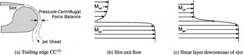
The Coanda effect describes the behaviour of a fluid moving tangentially to a convex (typically circular) surface. The flow adheres to the curved surface as a result of the pressure gradients within the jet flow (see Fig. 1(a)). The position of the separation and stagnation points at the trailing and leading edges of the aerofoil are altered due to blowing a jet over the Coanda surface, causing a change in lift.
Schematic of flows at trailing edge.

CC usually requires a high-speed jet of air up to four times the freestream speed(Reference Alexander, Anders, Johnson, Florance and Keller2), which attaches to the Coanda surface. As this high-speed jet meets the relatively lower-speed air in the freestream, the jet entrains the fluid within the freestream, which is then also turned around the Coanda. The entrainment is due to the mixing within a shear layer between the jet and the freestream travelling at significantly different Mach numbers. Figures 1(b) and 1(c) show simplified schematic diagrams of the flows that occur at the slot exit and just downstream of the slot. The momentum of the jet influences the boundary layer and accelerates the local freestream flow.
For aerofoils in the transonic regime, a supersonic Coanda jet is necessary to achieve a significant change in lift. In addition to shear layers, there is a possibility of shock boundary-layer interactions occurring on the surface of the Coanda devices if the jet becomes under-expanded(Reference Carpenter and Green3). Depending on the severity of the shock boundary-layer interaction, the jet can detach completely from the Coanda surface(Reference Sawada and Asami4). At transonic speeds, the shock on the upper surface of the aerofoil also alters the boundary-layer flow leading to the CC device at the trailing edge (Fig. 1(b)), which can affect the behaviour of the Coanda jet flow(Reference Abramson and Rogers5).
For an aircraft to successfully use a CC system, it would need to be effective over a wide range of flight conditions, including different altitudes. Changes in altitude as well as engine settings will create differences in the pressure ratio the Coanda device is operating at. Therefore, it is crucial to consider the CC device for a wide range of pressure ratios, mainly a range of conditions with under-expansion and, for cases where a converging-diverging nozzle is used, also over-expansion cases.
Studies on transonic CC have shown that the shape of the Coanda surface plays an important role in the effectiveness of the CC device at transonic speeds(Reference Alexander, Anders, Johnson, Florance and Keller2,Reference Abramson and Rogers5-Reference Schlecht and Anders7) . Parameters such as the Coanda radius-to-slot height ratio at the slot affect the attachment of the Coanda jet and the range of blowing rates (and nozzle pressure ratios) for which the jet remains attached to the Coanda. Experimental investigations into elliptical Coanda surfaces have concluded that more eccentric ellipses and smaller slot heights perform most favourably in transonic flows(Reference Alexander, Anders, Johnson, Florance and Keller2,Reference Englar6,Reference Schlecht and Anders7) .
Alternative methods of promoting supersonic Coanda jet attachment have been studied in conditions without a freestream flow. Converging-diverging nozzles have been shown to increase the detachment pressure ratio(Reference Carpenter and Smith8,Reference Gregory-Smith and Senior9) by expanding the jet flow further than a converging nozzle and limiting under-expansion. The introduction of a step between the Coanda surface and the jet exit of a converging nozzle also increased the detachment pressure ratio(Reference Carpenter and Smith8,Reference Gregory-Smith and Senior9) .
There is a lack of research on supercritical CC aerofoils; only subsonic studies have been conducted to date(Reference Jones, Yao and Allan10). For this reason, in this work, the performance of a supercritical aerofoil at transonic conditions with a CC device will be investigated. We aim to assess the aerodynamic feasibility of replacing ailerons for transonic flight control on a typical supercritical section. The feasibility of using devices such as converging-diverging nozzles and stepped Coanda surfaces for circulation control with a transonic freestream will be investigated. The abilities and limitations of such devices have not previously been considered for transonic circulation control.
In the present work, we focus on the effectiveness of CC devices for a range of nozzle pressure ratios on a supercritical aerofoil in a transonic cruise condition. Comparisons against the characteristics of the supercritical CC aerofoil with an aileron deflection and also with published experimental results form part of this study. In addition, a design study will be performed to examine the effect of various CC device configurations. We consider the effects of Coanda radius–to–slot height ratio, converging-diverging nozzles, and stepped Coanda surfaces, which will be investigated for increasing CC effectiveness for a transonic supercritical CC aerofoil.
Increasing the Coanda radius-to-slot height ratio (r/h) increased the Nozzle Pressure Ratio (NPR) that caused detachment of the jet, with a marginal increase in lift. The use of a simple step was found to extend the NPR and momentum coefficients range for which the jet remains attached. An increase in usable C μ = 0.004 was found when using the step, this extension increased the lift authority available to the circulation control system by C l = 0.1 compared with a similar device without a step. A converging-diverging nozzle designed for the conditions at which a jet from a converging nozzle with the same r/h separated was found to be equally effective as the stepped Coanda device.
The current paper first reviews related work in CC and supersonic Coanda flows, followed by a description of the numerical methods employed. A validation exercise of the solver against experimental results of a supercritical aerofoil with aileron deflection will be presented. The same aerofoil section was modified into a supercritical CC aerofoil, and forces and moments for blowing over several Coanda devices were compared with those from using an aileron. Finally, a summary of the findings and conclusions are made with recommendations for future research.
2.0 REVIEW OF RELATED WORK
CC using the Coanda effect for use as a means of generating an increase in lift over an aerofoil has been in consideration for at least 60 years(Reference Von Glahn11). Significant focus was invested on improving the lift of rotor blades with elliptical sections amid development of the X-Wing CC concept in the early 1980s(Reference Dvorak and Choi12). More recently, with concerns over aircraft efficiency and environmental impacts, CC has been studied to improve the lifting capabilities of fixed-wing aircraft while keeping within the capabilities of existing airport infrastructures(Reference Couluris, Signor and Phillips13). On fixed-wing unmanned air vehicles, it has been shown in subsonic flight that CC has the potential to replace moving parts for manoeuvrability control(Reference Cook, Buonanno and Erbslöh14). Other active flow control systems are also being studied, such as to allow for a reduction in the vertical tail size of commercial aircraft(Reference Lin, Andino, Alexander, Whalen, Spoor, Tran and Wygnanski15,Reference Whalen, Shmilovich, Spoor, Tran, Vijgen, Lin and Andino16) .
Much of the CC research to date has investigated flow control devices on aerofoils in the low-speed subsonic flight regime. As a result, modern numerical studies on CC have heavily relied on these subsonic freestream circulation control experiments(Reference Jones, Yao and Allan10,Reference Abramson17-Reference Nishino, Hahn and Shariff19) , such as those at the Georgia Tech Research Institute, which were intended specifically for Comptational Fluid Dynamic (CFD) validation and had a trailing-edge radius of approximately 10% chord(Reference Englar, Jones, Allan and Lin20). Laser Doppler Velocimetry measurements of the subsonic jet around the Coanda were made with a freestream Mach number of M = 0.12. Momentum coefficients up to C μ = 0.150 were investigated; however, it must be noted that C μ is inversely proportional to the square of the freestream Mach number via the dynamic pressure. This experiment demonstrated significant wall interference and angle of attack corrections to be suitable for CFD validation simulations(Reference Englar, Jones, Allan and Lin20).
Research on higher-speed transonic CC has produced a handful of experiments and numerical studies, which mostly took place in the 1980s on aerofoil sections intended to be used for helicopter blades on the X-Wing CC concept(Reference Abramson and Rogers5,Reference Englar6,Reference Wilkerson and Montana21,Reference Wood and Conlon22) . Such experiments were conducted in moderate-size wind tunnels, which introduced significant wall interference effects(Reference Pulliam, Jespersen and Barth23). The elliptical X-Wing–type sections typically had maximum thicknesses of approximately 15% chord, which do not have the characteristics of a supercritical aerofoil, as would be used on a fixed-wing aircraft. A supercritical CC aerofoil has been developed(Reference Jones, Yao and Allan10); however, transonic experiments on this section have not yet been published.
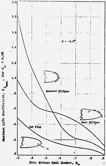
The difference between CC at subsonic and transonic speeds is highlighted in Fig. 2, showing the lift obtained by Englar(Reference Englar6) for an elliptical CC aerofoil over a range of Mach numbers. At low speeds, the “Rounded Ellipse” CC aerofoil outperformed the purely elliptical section; however, at high speeds, this was not the case. Schlecht and Anders(Reference Schlecht and Anders7) found that an elliptical Coanda surface was superior to a biconvex surface for both low subsonic and transonic freestreams, since the separation point of the jet is fixed by the sharp profile of the biconvex Coanda.
Maximum lift obtained by Englar with different Coanda geometries at range of Mach numbers for C μ ⩽ 0.08.(Reference Englar6)

Alexander et al(Reference Alexander, Anders, Johnson, Florance and Keller2) recognised a void in the public domain of data for transonic CC aerofoils, specifically those intended for fixed-wing aircraft. A series of experiments were published in 2005 on a 6% thick elliptical aerofoil with a 0.75% circular camber(Reference Schlecht and Anders7) in the NASA Transonic Dynamics Tunnel over a range of Mach numbers up to M = 0.84. Three different Coanda designs were considered, each with a range of slot heights. Coanda surfaces with larger major to minor axes performed more favourably than smaller elliptical Coanda surfaces; a greater maximum lift was achieved and detachment of the jet was delayed until higher momentum coefficients. A maximum sectional ΔC l = 0.25 was achieved at a peak C μ = 0.008 using an elliptical Coanda device with a 2.98 : 1 aspect ratio. The same slot height but with a 1.78 : 1 elliptical Coanda device had a maximum ΔC l = 0.2 at a peak C μ = 0.005. Following these peak values, a “C μ-stall” was observed, whereby further increases in blowing reduced ΔC l as the jet detached from the Coanda surfaces.
In 2006, Swanson et al(Reference Swanson, Rumsey and Anders24) performed two dimensional RANS simulations of the 16% thick, elliptical 103RE aerofoil(Reference Wilkerson and Montana21), however the simulations were limited to M = 0.6 at α = 0.0. At these conditions, the flow over the aerofoil remained subcritical. It was found that each turbulence model tested (Spalart-Allmaras, Menter SST, Spalart-Allmaras with Curvature Correction and EASM-k-ω) failed to predict the pressure distribution over the aerofoil surface at M = 0.6. In addition, the separation point of the jet from the Coanda surface was poorly predicted. The Spalart-Allmaras with Curvature Correction model gave reasonable results but only after unrealistic a-posteriori modifications to the baseline model constants(Reference Swanson, Rumsey and Anders24). This highlights that even with modern CFD methods, accurate predictions of CC remain a challenge.
Following the previous numerical studies on transonic CC discussed above, the understanding of the modelling requirements is improving due to increasing capabilities and experience with improved turbulence modelling approaches. Due to the lack of available experimental data for CFD validation of CC at transonic conditions, it is difficult to fully address and identify shortcomings in current CFD approaches. Despite this, however, CFD is the only currently feasible way to conduct a design investigation on CC devices in conditions relevant to transonic flight of aircraft.
To limit the detachment due to under-expansion of the jet, a converging-diverging nozzle can be used to expand the flow to the ambient pressure. In experiments on supersonic Coanda jets in still air, Cornelius and Lucius(Reference Cornelius and Lucius25) showed that a simple converging-diverging nozzle extends the range of operating pressures at which the Coanda jet remains attached. Bevilaqua and Lee(Reference Bevilaqua and Lee26) reported on a method of characteristics design approach that skews the velocity and pressure profile along the jet exit such that the pressure and velocities at the Coanda surface are lower and higher, respectively. Using the radial velocity and pressure profiles of an irrotational vortex at the slot exit, jet attachment was promoted(Reference Bevilaqua and Lee26).
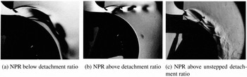
Other experimental studies have shown that introducing a step between the jet exit and Coanda surface can promote attachment at higher pressure ratios by preventing shock-induced separation(Reference Carpenter and Smith8,Reference Gregory-Smith and Senior9) . Carpenter and Smith(Reference Carpenter and Smith8) and Gregory-Smith and Senior(Reference Gregory-Smith and Senior9) have studied the effect of using a step to mitigate the effects of the under-expansion. By introducing a step, the shock waves due to under-expansion interact with the shear layer formed as a result of the step. The step also aids attachment by providing a region of low pressure, which turns the jet towards the surface(Reference Carpenter and Smith8). Figure 3 shows three Schlieren images from experiments by Gregory-Smith et al(Reference Gregory-Smith and Senior9,Reference Gregory-Smith and Gilchrist27) , where the NPR is close to the value at which the jet detached from the surface. Shown in Figs 3(a) and 3(b) are unstepped results before and after jet detachment, an increase in plenum pressure caused the jet to detach. For the same slot height and Coanda radius, including a step increased the detachment pressure ratio by 25%.
Schlieren of unstepped(Reference Gregory-Smith and Gilchrist27) (a) and (b), and stepped(Reference Gregory-Smith and Senior9) (c) supersonic Coanda jets near detachment.

Summarising the findings from this review of the literature, we find that all transonic circulation control studies considered previously have been limited to elliptical aerofoil sections. In addition, investigations into the effect of different Coanda devices for transonic circulation have essentially only studied the change of curvature at the slot exit. This work instead considered the use of CC on a supercritical aerofoil. We also aim to identify that the use of a stepped supersonic Coanda jet can be used effectively with a transonic freestream.
3.0 NUMERICAL METHODS
3.1 Navier-Stokes solver
The Helicopter Multi-Block (HMB) CFD code(Reference Steijl, Barakos and Badcock28-Reference Barakos, Steijl, Badcock and Brocklehurst31) is used for this work. The code has been validated for a number of applications, including helicopters, wind turbines, turboprops, and high-speed unmanned combat aerial vehicles(Reference Barakos, Steijl, Badcock and Brocklehurst31-Reference Lawson and Barakos33). In addition, validation of the solver and boundary conditions for CC has been conducted by Hoholis(Reference Hoholis, Steijl and Badcock34).
HMB solves the compressible, unsteady Reynolds-averaged Navier-Stokes equations on block-structured grids using a cell-centred finite-volume method for spatial discretisation. The convective fluxes are evaluated using Osher’s upwind scheme for its robustness, accuracy, and stability properties. MUSCL variable extrapolation is used to provide second-order accuracy with the Van Albada limiter to prevent spurious oscillations around shock waves. An implicit time-integration method is employed, and the resulting linear systems of equations are solved using a pre-conditioned Generalised Conjugate Gradient method. For unsteady simulations, an implicit dual-time stepping method is used, which is based on Jameson’s pseudo-time integration approach.
The solver has a library of turbulence closures, which includes several one- and two- equation turbulence models(Reference Wilcox35-Reference Spalart and Allmaras38) and also non-Boussinesq versions of the k-ω model(Reference Wallin and Johansson39,Reference Grigoriev, Wallin, Brethouwer and Johansson40) . Turbulence simulation is also possible using Large-Eddy and Detached-Eddy Simulation.
3.2 Momentum coefficient
The supply of air for the plenum for circulation control is often taken from bleed air from the jet engine of the aircraft(Reference Cook, Buonanno and Erbslöh14). As a result of this, the efficiency of the circulation control device is critical; mass flow taken from the engine reduces the power available for forward thrust. The jet momentum coefficient (C μ) is often used as a measure of blowing over a circulation control device, which is defined as
 $$\begin{equation}
C_{\mu } = \frac{\dot{m_{j}}V_{j}}{q_{\infty }A},
\end{equation}$$
where
 $\dot{m_{j}}$
is the mass flow rate through the slot exit, and A is the surface area of the aerofoil. In circulation control experiments,
 $\dot{m_{j}}$
is usually measured using a flow venturi meter, and V
j
is calculated from isentropic equations using the plenum pressure. Here, the plenum pressure ratio is fixed and the momentum coefficient is calculated a posteriori by integrating the solution along the slot exit.
An important and widely used metric for defining the efficiency of a CC system is the lift augmentation ratio ΔC l /C μ. Alexander et al(2) state that circulation control performance is considered as “good” for ΔC l /C μ > 50. In their experiments on the 6% thick elliptical wing, they found a maximum augmentation ratio of 37 for M = 0.8. In addition Abramson and Rogers(Reference Abramson and Rogers5) achieved ΔC l /C μ = 27 at M = 0.7 and ΔC l /C μ = 10 at M = 0.8 on their 16% thick elliptical aerofoil.
3.3 Reservoir boundary condition
A reservoir boundary condition is used to fix the desired pressure and density ratios based on the assumption that the supply has been isentropically compressed. The stagnation pressure and density are fixed by NPR at the reservoir boundary, while velocities at the face are allowed to vary with the condition that no gradients form across the boundary.
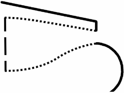
Force contributions of pressure and C μ from this internal reservoir boundary face are included in the calculation of the total forces and moments, following the approach presented by Min et al(Reference Min, Lee, Englar and Sankar41). The pressure and viscous terms are calculated on the external and internal solid surfaces of the wing, while other surfaces such as end plates are excluded. Contributions due to the pressure force and momentum addition of the jet are considered at the reservoir boundary. Figure 4 shows an illustration of the surfaces considered for the calculation of the forces and moments.
Diagram of trailing edge of circulation control aerofoil. The solid lines are considered as external surfaces, dotted lines are the internal no-slip plenum surfaces and the dashed line is the reservoir boundary condition.

4.0 TRANSONIC FLOW OVER A SUPERCRITICAL AEROFOIL WITH AILERON DEFLECTION
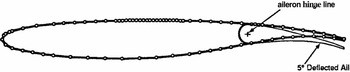
The supercritical McDonnell Douglas DLBA032 aerofoil section (Fig. 5) was chosen from the AGARD CFD validation database(Reference Elsenaar, Waggoner and Ashill42) due to the availability of experimental data with an aileron deflection in a transonic freestream. The DLBA032 is a supercritical aerofoil with a thickness of 12% chord and an aileron of 25% chord length. Experiments were conducted at a Reynolds number range of Re = 5 × 10⁶ to Re = 25 × 106, an aileron deflection of δ = −5° to δ = 5° and M ≈ 0.72. To promote transition in the experiments, a boundary-layer trip was placed at x/c = 0.15 and x/c = 0.28 on the upper and lower aerofoil surfaces, respectively. This trip was not taken into account for the present simulations, where a fully turbulent flow was assumed.
Douglas DLBA032 geometry(Reference Elsenaar, Waggoner and Ashill42).

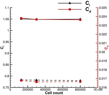
Two dimensional simulations were conducted on this geometry since the original dataset was reported to be suitable for such modelling approaches(Reference Elsenaar, Waggoner and Ashill42). The data presented in the AGARD report included corrections regarding the wind-tunnel interference. Grids were built using mesh densities and refinement strategies using conclusions from preliminary grid refinement studies of the DLBA032 with flap deflection, which is summarised in Fig. 6. The conclusions of this grid refinement study indicated that approximately 300,000 cells were sufficient to produce grid independent results for both deflected and un-deflected aileron cases. The following cases apply these findings with grids generated such that y + ≈ 1 initial grid spacing in the wall normal direction is applied, as required by the k − ω-type turbulence models employed.
Effect of grid refinement on lift and drag for simulations of the DLBA032 with and without (dashed lines) aileron deflection. Here, M ≈ 0.715, Re = 5 × 10⁶ at angles of attack of α = 1.183° with a 3° deflection and α = 1.342° without aileron deflection.

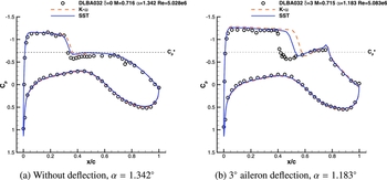
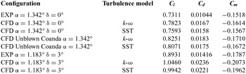
Figure 7 shows the pressure distributions for the DLBA032 with an un-deflected aileron (Fig. 7(a)) and a deflection of 3° (Fig. 7(b)). Without the deflection, the lower surface pressure distribution predictions agree well with the experimental data, and the shock location is within 5% chord (Fig. 7(a)). The upper surface suction is greater than the experiment; however, the overall trend agrees. Table 1 shows that with the SST model, the change in lift is approximately 3% above the measured lift from the experiment.
Experimental and predicted pressure distribution for the DLBA032 with and without aileron deflection at M ≈ 0.715, Re = 5 × 10⁶.

Comparing sectional lift, drag and pitching moment behaviour of the DLBA032 at M ≈ 0.715 and Re ≈ 5 × 10⁶ with and without aileron deflection

With the deflected aileron, the suction near the leading edge is over-predicted, and the shock is predicted approximately 15% aft of the experiment, as shown in Fig. 7(b). A similar finding was found by Londenberg(Reference Londenberg43) for Re = 5 × 10⁶ with a 2° aileron deflection. The agreement in the lift coefficient as shown in Table 1 is approximately 11% above the experimental data, due to the poor prediction of the shock location. It is emphasised, however, in the AGARD report that there is some uncertainty about the correction methods employed and that the dataset should be taken for qualitative trends(Reference Elsenaar, Waggoner and Ashill42).
5.0 EVALUATION OF COANDA DESIGNS IN TRANSONIC FLOW
The DLBA032 was modified to include a Coanda device by increasing the thickness of the trailing edge along the camber line. The rear 30% of the aerofoil was thickened symmetrically around the camber line, changing the trailing-edge thickness from 0.55% in the baseline aerofoil to 1.23% to accommodate a Coanda surface. Figure 8 shows the modified aerofoil geometry with a CC device.
Modified geometry with CC device.

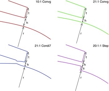
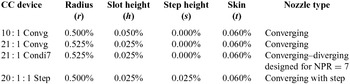
The first CC device considered used a circular Coanda surface with a 0.5% chord radius and 0.05% chord slot height (10 : 1 Coanda radius–to–slot height ratio). The design allowed for slots on the upper and lower surface; however, the current investigations use upper slot blowing exclusively, see inset Fig. 8. Between the slot and upper surface of the aerofoil, a thickness of t = 0.06% chord was applied as a skin thickness. This skin thickness was maintained for all subsequent shape modifications to ensure comparisons between geometries that were not affected by a change in this parameter.
This sensitivity study considers four different Coanda designs to evaluate the effects of shock boundary-layer interactions and the radius of curvature-induced detachment of the jet. To assess the influence of the curvature at the slot exit, a Coanda geometry was designed with a larger Coanda radius–to–slot height ratio (21:1). Converging and converging-diverging nozzles were used to assess the effects of under-expanded and fully expanded Coanda jets on CC. In addition, a stepped geometry with a converging nozzle was investigated to assess whether findings by Gregory-Smith and Carpenter(Reference Carpenter and Smith8,Reference Gregory-Smith and Senior9) can be applied to CC with a transonic freestream. The descriptions of the Coanda devices used in this study are summarised in Table 2 and Fig. 9; all other geometric features remain the same between the four designs.
Diagrams of trailing-edge devices.

Trailing-edge device details (dimensions in % chord)

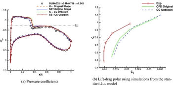
To establish that the modifications made to the DLBA032 did not significantly change the behaviour of the aerofoil, the unblown case was compared with the un-deflected aileron over an angle-of-attack range. Figure 10 shows the pressure coefficients and drag polars for the DLBA032 without aileron deflection and with an unblown CC device fitted as shown in Fig. 8. The shock position of the CC geometry is slightly further aft, which induces greater lift than the original shape as shown in Table 1. The shape of the lift-drag polar in Fig. 10(b) suggests that the effects of the thickened trailing edge and CC device are small, with an approximate 0.001 increase in the drag coefficient. However, the characteristics of the lift-drag polar from the original aerofoil geometry were effectively maintained.
Comparing unblown CC DLBA032 with original shape without aileron deflection.

Each CC case considered below was simulated at a freestream value of α = 1.342°, M ∞ = 0.716 and Re = 5.028 × 10⁶.
5.1 Grid refinement
Four grids were built with cell counts between approximately 100,000 and 900,000. Each finer grid was uniformly refined across the entire domain. An initial grid spacing of y + ≈ 1 in the wall normal directions was used for all grids, where y + was calculated based on the freestream Reynolds number. For a circular Coanda shape with a 21 : 1 radius–to–slot height ratio, the effect of grid refinement on the lift and drag on the aerofoil was assessed at the conditions described above with blowing at NPR = 4.0.
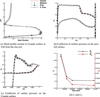
Figure 11 shows the effect of the grid size on the DLBA032 section with CC. Figure 11(a) shows the Mach profile of the jet and aerofoil boundary layer at the trailing edge, taken 3.0h from the slot exit. Minor differences occur in the jet profiles between the “Fine” and “V. Fine” grids with 400,000 and 900,000 cells, respectively. These differences, however, do not have a significant effect on the surface pressures on the main aerofoil, nor the Coanda surface (Figs 11(b) and 11(c), respectively). As a result, the Fine grid is within 0.01% of the lift and 0.1% of the drag coefficients from the solution using the finest grid (V.Fine on Fig. 11), as shown in Fig. 11(d), suggesting that the 400,000 cell grid produces sufficiently grid-independent results.
Effect of grid refinement on the 21 : 1 Coanda device at NPR = 4.0.

5.2 Converging nozzle with 10 : 1 radius-to-slot ratio (10 : 1 Convg)
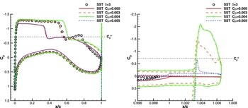
The simulated pressure coefficients for the DLBA032 aerofoil with a circular Coanda device with 10 : 1 radius-to-slot ratio are compared with an aileron deflection of 3° in Fig. 12. As with the NASA 6% elliptical CC aerofoil results, the shock moves aft with blowing, which is consistent with an increase in lift and circulation. The symbols in Fig. 12 represent the simulated results of the aileron deflection case at the same conditions.
Predicted pressure coefficients for Douglas DLBA032 at α = 1.342°, M = 0.716 and Re = 5.028 × 10⁶ for an aileron deflection and with blowing at C μ ≈ 0.003, C μ ≈ 0.004 and C μ ≈ 0.005 for the 10 : 1 configuration. Symbols here represent the simulated pressure distribution of the deflected aileron case at the same freestream conditions and turbulence model.

Comparing the predicted results of the aileron deflection and blowing over the 10 : 1 configuration at C μ = 0.003, the lower surface and the front section of the aerofoil have similar pressure distributions. The rear section of the aerofoil with blowing has more suction and does not have the characteristic peak in suction at the hinge line. This additional suction towards the trailing edge generates an increase in the ‘nose down’ pitching moment compared to that of a 3° aileron (Fig. 13).
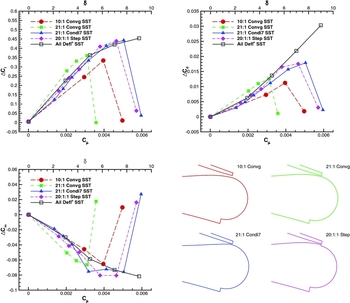
Comparing lift, drag and pitching moment coefficient characteristics with blowing over various Coanda surfaces against aileron deflection on the DLBA032 at M = 0.716, α = 1.342° and Re = 5.028 × 10⁶.

With increased blowing, the sectional lift, drag and pitching moment coefficients on the aerofoil increase. Figure 13 shows the behaviour of the loads due to blowing, also shown are predicted loads for the aerofoil at a range of aileron deflection angles. At a similar lift coefficient to that of a deflected aileron of 3°, blowing over the 10 : 1 configuration at C μ = 0.003 resulted in a smaller drag increase.
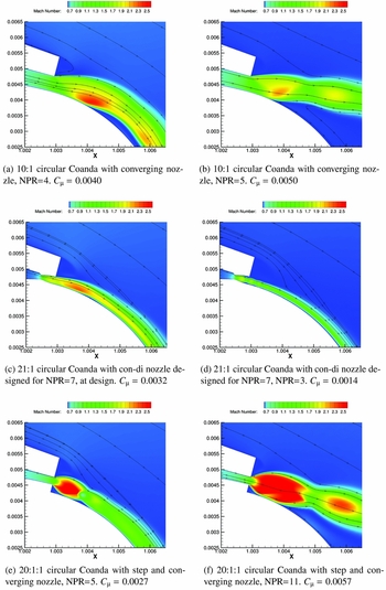
Additional blowing results in separation of the jet from the Coanda surface, due to the increased under-expansion of the jet. For C μ = 0.004 the jet separated from the Coanda surface, however in this case the jet re-attached to the surface. This re-attachment may be due to the low pressure within the separated bubble, as shown in Fig. 14(a). In Fig. 14(b), Mach contours using a moderately higher blowing rate of C μ = 0.005 are shown, where the jet is detached. The shock impinging on the Coanda surface is too strong for the flow to re-attach to the Coanda. As seen in Fig. 14(b), the separation bubble does not form, so the mechanism to re-attach the jet is not present.
Contours of Mach number for various Coanda designs using the k-ω SST turbulence model.

The lift characteristics for blowing at C μ = 0.003 suggest that it is possible to replicate the lift achieved with a 3° aileron deflection using CC in this flight regime, with a reduction in the drag and an increase in the pitching moment, as shown in Fig. 13. For this configuration, a blowing rate of C μ = 0.005 caused detachment of the jet. While the jet remains attached, a lift augmentation ratio of ΔC l /C μ = 84 was achieved.
5.3 Converging nozzle with 21 : 1 radius-to-slot ratio (21 : 1 Convg)
The effect of changing the radius-to-slot height ratio was investigated by halving the slot height of the 10 : 1 Coanda trailing-edge device, resulting in a surface with a radius and slot height of 0.525% and 0.025% chord lengths, respectively, and a 21 : 1 Coanda radius-to-slot ratio. At NPR = 5 the jet detached from the 10 : 1 Convg geometry, while at this pressure ratio the jet remained attached to the 21 : 1 Convg Coanda surface.
Figure 13 shows that at C μ = 0.002 (NPR = 4.0), the SST predictions gave comparable performance to the converging nozzle over the 10 : 1 surface at C μ = 0.003 (NPR = 3.0) and also the aileron deflection of 3°. For the same blowing rate, the 21 : 1 device produced approximately 50% higher lift augmentation ratio than the 10 : 1 CC device, resulting in a ΔC l /C μ = 134.
Similarly to the 10 : 1 configuration, further blowing detached the jet due to the strongly under-expanded jet flow at C μ = 0.0035 (NPR = 7.0).
By increasing the radius of curvature near the slot exit, the boundary layer within the jet experiences a weaker adverse pressure ratio. As a result, the jet boundary layer is able to cope with a stronger shock associated with under-expansion at a higher pressure ratio when using the 21 : 1 configuration compared with the 10 : 1, above.
5.4 Converging-diverging nozzle with 21 : 1 radius-to-slot ratio (21 : 1 Condi7)
Bevilaqua and Lee’s(Reference Bevilaqua and Lee26) method of characteristics approach fixes a desired irrotational vortex profile along the slot. The two-dimensional characteristics equations are solved to determine the nozzle wall profiles from the slot exit to the nozzle throat for a given pressure ratio and Coanda radius. This method of characteristics procedure was applied to the nozzle walls of the 21 : 1 configuration to design a nozzle to perform at NPR = 7.0. At this pressure ratio, flow from a purely converging nozzle failed to attach, as described in Section 5.3. The resulting asymmetrically contoured converging-diverging nozzle is shown in Fig. 9. In designing the nozzle, the exit slot height from the 21 : 1 Convg device is retained at 0.025% chord. The contouring of the nozzle gave an effective throat height of 0.015% chord, resulting in an expansion ratio of 1.67. For choked conditions, this results in a reduced mass flow rate.
Figure 14(c) shows the converging-diverging nozzle operating at the design condition NPR = 7. A relatively weak shock occurs at the slot exit, followed by a small separation bubble on the Coanda surface at approximately x = 1.004.
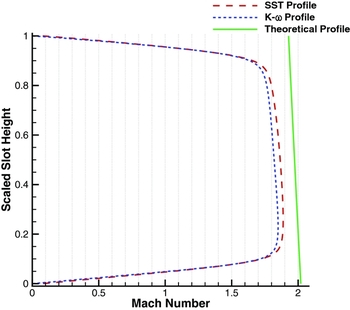
Although the nozzle was designed to fully expand the jet, the used method of characteristics did not account for the boundary layer. The effective nozzle contour as seen by the flow, due to the displacement thickness, was found to significantly reduce the expansion rate and so the jet was under-expanded. This can be seen from the Mach number profile at a station at the slot exit in Fig. 15, where the theoretical irrotational vortex profile is also shown. The SST model predicted a thinner boundary layer than that of the k-ω; however, both models gave a slope similar to the idealised profile at a reduced value for the mean Mach number.
Profile of Mach numbers for the SST and k-ω models at the slot exit for the converging-diverging configuration with a 21 : 1 radius-to-slot ratio at design condition for blowing at PR7.

For a pressure ratio of 9.0, the jet emanating from the converging-diverging nozzle under-expands; however, the magnitude of under-expansion is lessened by the nozzle. This allows the jet to adhere to the Coanda surface and gives a lift increment of ΔC l = 0.4077 using the SST model. An approximate linear change in the lift and drag coefficients using the converging-diverging Coanda until C μ ≈ 0.004 is shown in Fig. 13. Again, due to under-expansion, the jet eventually detached from the Coanda at C μ ≈ 0.006 (NPR = 13.0).
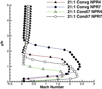
Figure 16 shows the differences between the jet profiles using the converging and the converging-diverging nozzles at NPR = 4 and NPR = 7 both with a 21 : 1 Coanda radius-to-slot height ratio. At NPR = 4, the C μ of the converging nozzle was approximately 10% higher than that from the converging-diverging nozzle, however the ΔC l was 54% higher using the converging nozzle as shown in Fig. 13. The reduction in ΔC l at the same NPR is possibly due to the reduction in mass flow rate through the shorter throat height of the converging-diverging nozzle. The under-expansion of the jet from the 21 : 1 Convg device appears to entrain more of the freestream than when using the 21 : 1 Condi7 nozzle at the same conditions. This under-expansion is an impediment at higher nozzle pressure ratios, however, because it also brings about shock-induced separation of the Coanda boundary layer. By expanding the flow, the extent of the separation is reduced and detachment occurs later.
Mach profile normal to Coanda surface at 3.0h from the slot exit.

Figure 14(d) shows contours of Mach number for an over-expanded nozzle on the DLBA032. Although the flow separated inside the nozzle, the jet remained largely attached to the Coanda surface for NPR = 3.0 (C μ = 0.0014). In all over-expanded cases (C μ < 0.003) using this nozzle designed for NPR = 7, a reduction in lift augmentation ratio and thus efficiency was observed. Comparing this with the same radius-to-slot height ratio, ΔC l /C μ with 21 : 1 Condi7 was 75% of the augmentation ratio achieved from the convergent only nozzle 21 : 1 Convg.
In contrast to the other designs, the gradient of the ΔC l vs C μ plot for the 21 : 1 Condi7 in Fig. 13 initially increases as C μ increases. Up until the design condition at C μ = 0.0032 a maximum ΔC l /C μ = 105 was found. Following from the design point, the slope of ΔC l vs C μ begins to diminish.
5.5 Converging nozzle with a 20 : 1 : 1 radius-to-slot-to-step ratio (20 : 1 : 1 step)
Using the initial 21 : 1 purely converging configuration as described above (Section 5.3), the radius of the Coanda was decreased by 0.025% chord to give a radius of slot height of 0.5% chord while maintaining the 0.025% chord slot height. This produced a step between the exit of the converging nozzle and the Coanda surface.
Figure 14(e) shows the behaviour of the under-expanded jet at C μ = 0.0027, the shock cell structure can be seen which begins to follow the Coanda surface. At NPR = 7 (C μ = 0.0035), the flow from the same nozzle caused the jet to detach from the 21 : 1 configuration (described above), while including the step promoted attachment to the Coanda surface. Attachment of the jet remains up to NPR = 11.0 (C μ = 0.0057). As shown in Fig. 13, the behaviour of the jet over the stepped Coanda follows the same behaviour as that of the converging-diverging nozzle. A maximum ΔC l /C μ = 108 up to C μ = 0.0038 was found when using the stepped Coanda. Below the design point of the 21 : 1 Condi7 nozzle, the stepped geometry gave a greater ΔC l /C μ. At NPR = 11.0, the jet under-expands such that a shock boundary layer interaction with the Coanda is strong enough to separate the jet, despite the step (Fig. 14(f)).
5.6 Effect of angle-of-attack
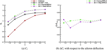
To assess the range of operability of CC in transonic flow, two representative CC cases are compared here with a deflected aileron case. The effect of increasing shock strength on the upper surface of the aerofoil is investigated by operating at steeper angles of attack. Figure 17 shows the effect of varying the angle of attack on the lift characteristics of CC and a 3° aileron deflection. The two CC cases shown are the 21 : 1 Convg and the 20 : 1 : 1 Step running at C μ = 0.0020 and C μ = 0.0027, respectively. Independent of trailing-edge geometry each case undergoes a stall as α increases, due to the stronger shock on the upper surface causing the boundary layer to separate, so a progressively smaller ΔC l as α increased. This gradual reduction in ΔC l is due to a strong shock wave separating the boundary layer on the upper surface of the aerofoil. The rate at which ΔC l degraded was approximately constant between the CC and aileron deflection cases as shown in Fig. 17 b, where the difference between circulation control cases and the 3° aileron are presented. These results suggest that the behaviour of CC is similar to that of a deflected aileron at the higher angles of attack considered. At higher angles of attack, degradation of the mean flow rather than the CC system appears to be the limiting factor in retaining control of the forces and moments. Such a result may mean that the well-understood principles of using ailerons in transonic flows could be applied to the use of CC.
Effect of angle of attack on C l at M = 0.716 and Re = 5 × 10⁶.

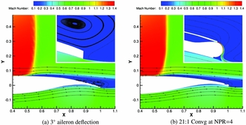
Figure 18 shows the effect of the aileron deflection and CC have on the flowfield at the trailing edge of the aerofoil. In both cases, a strong shock boundary-layer interaction occurred at approximately 55% chord, with the shock further aft for the CC case from the increased circulation generating additional lift. With CC, the trailing-edge separation is reduced in severity due to the additional boundary-layer momentum from jet entrainment and a favourable pressure gradient due to blowing. Although not investigated here, it may be possible that CC may offer some shock buffet onset alleviation.
Mach contours at the trailing edge of aileron deflection and CC cases at α = 5°, M = 0.716 and Re = 5 × 10⁶. Inset shows detail of the trailing edges at the same scale in both images.

5.7 Summary of results
An increase in the ratio between the radius of curvature and the slot height increased the CC effectiveness by providing an increase in total lift and also the lift augmentation ratio. This finding is in line with conclusions from experimental studies described in Section 2, where the local radius of curvature at the slot exit was increased by altering the eccentricity of elliptical Coanda devices(Reference Alexander, Anders, Johnson, Florance and Keller2,Reference Englar6) . Here we have shown that an increase in the ratio between the Coanda radius and slot height resulted in an increase in overall lift achievable.
The limiting detachment pressure ratio can be extended by using a suitably designed converging-diverging nozzle. In the cases considered in this paper, the converging-diverging nozzle was designed for the operating condition for which the jet detached using a convergent only Coanda device at the same radius-to-slot height ratio. Further extension may be possible by designing the converging-diverging nozzle for higher pressure ratios; however, a further reduction in efficiency is likely be observed.
Introducing a step between the Coanda surface and the slot exit also promoted a delay in detachment for CC with a transonic freestream. This was due to the shock boundary-layer interaction being replaced by a shock shear interaction. For very highly under-expanded stepped Coanda jets, the re-attachment shock was the cause of separation.
As shown in Fig. 13, each of the designs can be compared to an aileron deflection angle, the 10 : 1 Convg and 21 : 1 Convg devices achieved a maximum ΔC l equivalent to that of approximately 4° and 5° aileron deflection, respectively. Both converging-diverging and stepped devices gave an equivalent aileron deflection of approximately 7.5-8° before detachment.
6.0 CONCLUSIONS AND FUTURE WORK
The current work investigated the simulation of transonic CC for the supercritical DLBA032 aerofoil section. Results showed how, for a supercritical section in transonic conditions, fluidic circulation control can achieve similar performance as the aileron with moderate deflection angles.
The design study involved different nozzles, nozzle exit geometries and Coanda surfaces to investigate, which design performs most consistently over a range of blowing coefficients. It was found that replicating the lift, drag and moment characteristics of a 25% chord aileron at δ = 4.0° is possible with a converging nozzle and a Coanda radius-to-slot height ratio of 10 : 1. However, a wider range of operating pressure ratios was found for a 21 : 1 ratio. For the converging nozzle the limiting factor is the strong shock-induced separation created by the under-expansion of the nozzle flow.
The results for converging-diverging nozzles showed that, as expected, the under-expansion related shock-induced separation can be delayed to higher pressure ratios. Furthermore, for the converging nozzle, it was found that the shock-induced separation can be delayed by applying a small step in the geometry between the nozzle exit and the Coanda surface. It was shown that using either the converging-diverging or the stepped Coanda geometry can perform equivalently to an aileron deflection angle of up to 8°.
The effects of angle-of-attack were in addition considered with a comparison between circulation control and a 3° deflected aileron. The performance of the CC devices at a constant blowing rate performed similarly to the deflected aileron. Each device considered lost effectiveness at the same rate, due to the mean flow and upper surface boundary layer separating from a strong shock boundary-layer interaction.
The present study did not investigate the effects of different slot heights, nor a converging–diverging CC device with a step. Further work regarding these design choices is ongoing. In addition, an investigation into the effectiveness of the sizing of Coanda devices in transonic flows is recommended for future studies. In doing so it may be possible to minimise further the drag penalty due to the bluntness of the Coanda device.
For the Coanda device to replace flaps and ailerons completely, the system must be able to operate over the full flight regime, including take-off and landing and blowing over the lower Coanda surface. It is recommended that future studies would focus on actuation for all flight conditions and manoeuvre requirements, including the use of CC as a yaw control effector. Full system analysis to include the necessary air supply and its effects on engine bleed air and vehicle weight should form part of a future integration study. For the system to be considered for use on an aircraft, the effect of failure of one or more Coanda devices should be investigated. Initial tests may possibly include the combined use of flaps and CC devices; however, this would result in an increase of weight. The design and integration of fluidic control devices such as CC via the Coanda effect are currently being studied as part of the NATO Science and Technology Organisation task group, AVT-239(44).
ACKNOWLEDGEMENTS
The present research was supported by a doctoral scholarship from the Engineering and Physical Sciences Research Council of the UK, with additional sponsorship from BAE Systems and DSTL through the industrial CASE Award scheme.