




No CrossRef data available.
Toward an automated approach to the design of sheet metal components
Published online by Cambridge University Press: 12 February 2004
Abstract
The design of sheet metal components is perhaps one of the more challenging concurrent activities for design and manufacturing engineers. To aid this design process, a method is developed to encapsulate the constraints of sheet metal that make designing such components a tedious and iterative procedure. This project involves the implementation and testing of a geometric representation scheme for building feasible sheet metal components through the use of 17 grammar rules that capture manufacturing operations like cutting and bending. The implemented system has benefits both as a user interaction tool and as the basis for a computational design synthesis approach for designing sheet metal components. An example of a constructed sheet metal component is shown along with the method for invoking the sheet metal grammar to create this component.
Information
- Type
- Research Article
- Information
- Copyright
- © 2003 Cambridge University Press
1. INTRODUCTION
The use of sheet metal as a medium for building structural and functional components offers some advantages over bulk machined components such as those that are forged or machined. Sheet metal is inexpensive as a raw material, inexpensive to form, and produces lightweight and inexpensive components. The main shortcomings of sheet metal design are that resulting components have a limited rigidity and the parts are constrained by the inherent two dimensionality of the initial sheet.
Clever solutions to the design of sheet metal components can both reduce manufacturing time and energy and result in high quality components. Good design is based on how the design engineers manage the trade-offs among the manufacturing process and the design specifications. The concurrent efforts between the manufacturing engineers and the design engineers become complicated for even the simplest sheet metal components, resulting in an iterative and time-consuming design process.
The bulk of research aimed at improving sheet metal design is concerned mainly with the construction of dyes or the modeling of the sheet metal as it is being subjected to various manufacturing operations. The designing of actual sheet metal parts has been left to the experienced designer who learns how the limitations of sheet metal prevent certain part features and how features can be altered to achieve a more easily manufacturable part.
This paper presents several innovations that will lead to a design tool to aid the design process of sheet metal components. These innovations encapsulate the inherent constraints of sheet metal. First, we present a set of rules that govern basic sheet metal operations such as notching and slitting (Sections 3 and 4). This is followed by an algorithm (Section 5) for estimating the cost and energy needed to perform such operations. The design engineer can then use these tools to design parts that are successful at meeting both manufacturing and design constraints. In this way, the concurrent issues of sheet metal design are automatically and immediately introduced during the design of new parts.
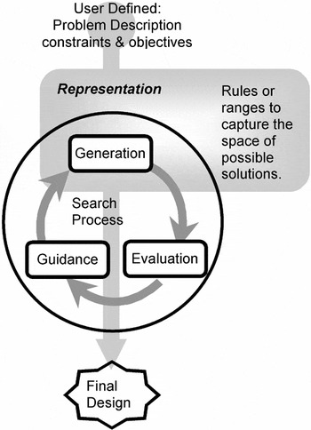
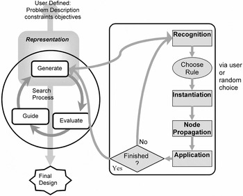
In addition to the use of these methods by the designer, our long-term goal is to computationally generate design concepts. Working within an optimization scheme, the tools presented here will help formulate a search process that will accept design specifications and ideally produce solutions that are optimal in both manufacturing and design specifications. Figure 1 presents a generic flowchart for most design synthesis methods such as search strategies or optimization routines. Initially, setting up the problem can involve declaring constraints and constructing objective functions. Within the execution of these generative techniques, there are four generic elements shown here: representation, generation, evaluation, and guidance. The representation is formulated by the programmer to capture the decision variables of the design problem. For example, in genetic algorithms, a popular generative technique (see overview in Mitchell, 1996), the representation is usually a bit-string that represents the key decision variables in the process. Upon this representation, candidate solutions are generated in the generation task. In genetic algorithms, this is done by mutating and “crossing over” existing or parent candidates. In Sections 3 and 4 of this paper, we present our framework for representing and generating sheet metal components. From the generated candidates, each one is evaluated in the evaluation task to determine how well it meets the objectives and constraints of the design problem. The genetic algorithm example is where fitness is calculated; our sheet metal process is where cost and energy predictions are made as described in Section 5. Based on the objectives calculated for the candidates, a guidance strategy is implemented to inform the search process of how to find better solutions in the subsequent iterations. In genetic algorithms, this is the “survival of the fittest” tournament selection, in which candidates with inferior fitness values are removed from the search. A guidance strategy for this automated generation of sheet metal solutions is our next research endeavor. Within the current implementation, the user is charged with this task. As either an automated generator of solutions or a user-interactive tool, this work has the distinct benefit of encapsulating the concurrent issues of sheet metal design by bringing the design and manufacturing issues into a single computational environment.

The generic flowchart for a search process has four basic tasks: representation, generation, evaluation, and guidance.
2. RELATED WORK
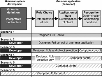
Representation and generation in the design process are done through the use of a fully implemented shape grammar (Stiny, 1980). In recent years, engineering researchers have discovered that shape grammars (originally a product of architectural research) provide a flexible yet ideally structured approach to engineering design methods (Cagan, 2001). The concept of a grammar is that an experienced designer can construct a set of rules to capture a designer's knowledge about a certain type of artifact. The grammar can be constructed such that any execution of the rules creates a feasible solution (see example in Longenecker & Fitzhorn, 1991) or captures the style of a specific period (see example of traditional Turkish houses; Cagdas, 1996) or a specific designer (Frank Lloyd Wright's prairie houses; Koning & Eizenberg, 1981). Because grammar research can occur at various levels of computational implementations, Chase (1998) developed a model to characterize different grammars. Figure 2 presents six scenarios that are ordered by the amount of human interaction versus computer interaction. At the current stage of this research, the sheet metal grammar falls under scenario 4, where the computer is responsible for the recognition and application of the rules and the updating of the candidate. The user interacts with the system to choose the rules to apply in order to build a complete design. In the future, we will explore this rule choice as an operation of a computational agent, thus classifying the system as a scenario 5 grammar under Chase's (1998) model.

The current sheet metal grammar is at scenario 4, where the computer determines the object and the matching conditions (recognition and application of rules).
An important offshoot of shape grammar research is the function grammar or graph grammar synthesis work (see Pinilla et al., 1989; Fu et al., 1993; Li et al., 2001). Similar to production systems in cognitive psychology (Klahr et al., 1987), graph grammars are comprised of rules for transforming nodes and arcs within a graph. These techniques create a formal language for generating and updating complex designs from a simple initial specification, or seed. The combination of manufacturing constraints and grammars was seen once before in the lathe grammar of Brown and Cagan (1997). In this work, the grammar that is developed operates on the nodes and arcs of a graph but generates a complete shape. The position of nodes within the graph directly represents elements of the sheet metal.
In formulating the sheet metal grammar, it was paramount to reference the numerous handbooks that describe the sheet metal design process and design limits in order to understand how to make the grammar function properly. The most useful of these have been Lascoe (1988) and Boothroyd et al. (1994), who address how manufacturing constraints directly impact the design decisions. Other research in sheet metal forming is often concerned with modeling the sheet as it undergoes various manufacturing operations (see Chappuis et al., 1993; Hardt et al., 1993; Hishida & Wagoner, 1993; Katayama et al., 1993). The Robotics Institute at Carnegie Mellon University has done some significant research in automated bending of sheet metal components. Their algorithms based on A* choose an optimized sequence of operations from different available options (for least cost) and also provide the necessary control signals for the tools to complete part production (see Bourne & Fussel, 1982; Cheng-Hua & Bourne, 1995; Gupta et al., 1998). The engineering design and drawing software PRO/E has a module called PRO/SHEETMETAL that is dedicated specifically to designing sheet metal components. This module helps users create features such as walls, bends, punches, notches, forms, and reliefs and also allows them to create complex geometry, convert solid parts to sheet metal, and automatically generate bend order tables.
Recently, sheet metal research has focused on a computational model that can be used during the design process. Computer-aided design tools have been developed to address specific needs in sheet metal design such as BendCAD (Wang & Sturges, 1996; Lin & Hong, 1998). Furthermore, Shpitalni and Lipson (2000; see also Lipson & Shpitalni, 1997) have set out to develop a systematic approach to representing sheet metal using Euler operators. Their work presents a similar approach to ours; however, it has not provided the set of legal operations to transform an initial sheet as is done here.
3. SHEET METAL GRAMMAR FUNDAMENTALS
The aim of this research is to develop a grammar for sheet metal components in order to capture the set of designs and manufacturing process paths that are intrinsic to sheet metal component design.
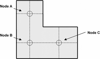
In our grammar, a design state is comprised of a “node” or a graph of nodes. A node is the smallest element of the sheet. As seen in Figure 3, this node can be viewed as a rectangular patch of sheet metal having certain properties such as length, width, and thickness. Each node can be bordered by four nodes in the east, south, west, and north directions. Within the C++ implementation, the node class has four pointers in the four neighboring directions mentioned above. A NULL in any direction means that the node is not connected to any other node in that particular direction and hence represents the physical edge of the sheet. For example, in Figure 3, node C is connected to node B in the westerly direction but has a NULL in the north, east, and south, because these are edges of the sheet. A collection of these nodes or patches, having a certain relative orientation with respect to each other, form the current state of the design. These orientations may change as a result of transformations applied to the current design state. The design changes are identical to the types of manufacturing operations that happen to the initial sheet as it is processed. Application of a typical sheet metal grammar rule consists of recognizing a node or graph of nodes with a particular structure as the “left-hand side” of the rule and then transforming it to give it a new structure and properties, as specified by the “right-hand side” of the rule. A presentation of the rules is provided in Appendix A.

An example sheet metal component represented by three nodes.
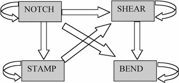
The grammar development process was a gradual one that included numerous problem-solving sessions and example problems to test the robustness of the representation. Any sheet metal component is manufactured by performing a certain set of operations. These sets of operations are traditionally constrained by the order in which the operations can be performed. Certain operations on the shop floor must be performed on the component before other operations can be performed on it. The rules that were to be developed had to take that intrinsic order into consideration. This is illustrated in Figure 4, where arrows in the direction of an operation indicate the different operations that can be performed on the component.

The four basic sheet metal operations: notch, shear, stamp, and bend. The arrows represent the ideal flow of operations. For example, bending should follow notching but not vice versa.
It is evident from Figure 4 that each operation can be performed on a sheet metal blank. It is interesting to note, as suggested by the figure, that the bend operation is and should be the last operation in the process for manufacture of the component. Similarly, notching can precede any other operation but cannot be performed after bending or stamping. Shearing can be performed after stamping, for example, trimming the edges of a stamped component. In addition to grammar rule order, the operations are also subject to parametric constraints, such as minimum length of cut, maximum length of cut, minimum and maximum angle of the bend, and so on.
The basic representation scheme for sheet metal components is the critical element in the development of the rules. Various approaches were considered. One possible approach is to represent a patch of sheet metal as four nodes (knots) connected to each other, signifying the vertices of the patch, where each node is associated with a relative position in space. A bend would signify a change in the knot structure and a subdivision of the patch. Similarly, shearing would cause a reduction of nodes. This boundary representation method is popular in computational geometry but is not used here because rules are dependent on the nature of neighboring patches and not simply on the location of the edges. Parametric information stored within each patch (i.e., node) such as the length, width, and thickness simplifies rule recognition and eliminates the need to store the absolute positions of these patches in space.
Currently, 17 rules have been developed for four basic sheet metal operations: slitting, notching, shearing, and bending. In addition to choosing the rules to be applied, the user must also select dimensions that are appropriate for the particular rule. As mentioned above, each rule is associated with a set of parameters that characterize the node. The grammar rules contain various parameters that require the user to choose rules and then choose values for the variables of the rule.
Grammar rules can be constrained so that no matter how the rules are applied, one can develop a large set of designs, which are guaranteed to be within a feasible design space. Thus, certain assumptions and constraints have been imposed on the rule selection algorithm to constrain the design space. These assumptions and constraints have been carefully determined so that they do not excessively narrow the design space, yet they prevent the designer from searching a space of infeasible designs. The assumptions and constraints made at this stage of the research are the following:
- The original shape of the sheet metal blank is a rectangle.
- All cutting and bending operations are orthogonal to the sides of the rectangle. (This does not mean that the bend angle is constrained to be a multiple of 90°.)
- No cutting can take place after a bend has been made; that is, all cutting operations on a part must be completed before bending is performed.
- No rebending can be done.
- Nodes already bent along a particular axis cannot be bent about the orthogonal axis.
- There are constraints for the minimum and maximum lengths of cuts, angles of bend, and widths of notches.
3.1. An example
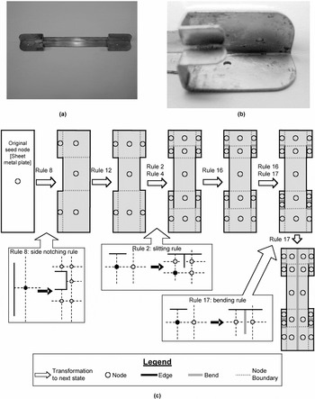
To elucidate the idea of a node and the application of a rule on a node, a step by step approach to the representation of the process path to manufacture a bracket is explained below, with the help of illustrations (Fig. 5). This small bracket or stilt, shown in Figure 5a and b, is used to separate and support mailboxes on a desk. This example includes various sheet metal operations such as notching, slitting, and bending and will be used throughout Section 4 to explain the steps involved in node application.

An example sheet metal component. (a) The component is a small bracket for supporting shelves. (b) A close-up of the end shows how bends and slits are arranged. (c) The grammar works by starting with a single blank upon which rules are applied to create the final shape.
Recall that a shape grammar needs a seed, or initial node, on which transformations occur. In the case of the bracket, the application of rules starts with a rectangular sheet metal plate having certain dimensions, which serves as the seed node. Performing an operation on the sheet metal blank can be simulated by executing rules on the current state of the graph of nodes.
4. STEPS IN THE GRAMMAR EXECUTION
This section describes a C++ implementation for the representation and generation tasks of the design synthesis flowchart shown in Figure 1. A more detailed flowchart of what happens within the generation block is shown in Figure 6. In this section, we describe the four main subtasks of generation: recognition, instantiation, node propagation, and application. Each of these is implemented as a separate function.

Within the context of a computational design synthesis process shown in Figure 1, the grammar presented in Section 4 is an inner loop to the task of generating new designs.
Throughout this section we will use the example shown in Section 3.1 to illustrate how these tasks are accomplished.
4.1. Recognition
There are two possible methods for recognizing applicable rules in a shape grammar. One is to select a rule and to recognize all the nodes that conform to that rule. The other method, which is employed here, is to select a node and then check each rule and orientation of that rule to determine if it is applicable on that node. Selection of a node is done using the master linked list, which is an unordered list of all the addresses to the nodes in a graph, and traversing through the list.
The fundamental method for recognizing which rules are applicable is to check for the existence, or lack of existence, of edges (recall that edges are neighbors that point to NULL). Checks are also made to determine whether a bend has occurred. If a bend has occurred, no slitting or notching rules can be applied. This is done by introducing a global “no cut after bend” variable that is set to true if a bend rule has been applied, and no bend can be rebent to a different angle. This is prevented by checking the x and y angles of the node under consideration and the corresponding angles of its neighbors. In addition, if a node has been bent in a particular direction, it cannot be bent in the direction perpendicular to its current bend unless a slit has been made previously to make the two orthogonal bends possible. Such checks are performed on every node.
Based on the constraints for each rule, a list of applicable rules is generated for every node. This list of all the rules applicable on every node is stored in a linked list of rule choices. Each rule choice has as its properties the rule number, orientation, and the node on which it can be applied. In the example, the Recognition function recognizes the existence of a node or a graph of nodes and establishes a list of possible rules to be executed on the node(s). For example, in Figure 5, the function recognizes that rule 8 can be applied to the root node; similarly, in the next step it recognizes that rule 12 can be applied to the graph of nodes.
4.2. Instantiation
After rule recognition is done, a list of all the applicable rule choices for every node is generated. This rule choice is a valid execution that can be performed on the given design state and includes the rule number, where it is applied, and its orientation. The user is presented with the list of these choices and he/she can choose any rule choice to achieve a new feasible design state. After selecting a rule, it must now be instantiated.
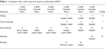
Because the grammar is parametric, dimensions within the rule must be specified. The rules are bound by a framework of constraints that are verified while selecting the values for the parameters of the rule. Parameters for every rule are different, and hence the instantiation code is different, depending upon the degrees of freedom of each rule. In Table 1 each of the 17 grammar rules is indicated by how many degrees of freedom it has. These degrees of freedom are represented by physical dimensions such as the depth of a notch or the angle of a bend.
Grammar rules with respective degrees of freedom (DOF)

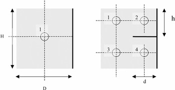
To clarify, we take the example of a simple slitting rule (Fig. 7, rule 1). All 16 rules are provided in Appendix A. In the figure, the height (H) and depth (D) are the initial dimensions of the node. A slit of a certain depth is made in the node. This results in the formation of three new nodes. The instantiation of dimensions for the nodes is done in the “instantiate rules” function. In this case, the depth of the slit causes a change in the dimensions of node 1. The height of this node is now changed from H to h and its width is now D − d, where d is the depth of the slit. This change of dimension, as well as the instantiation of the dimensions for the newly created nodes, is carried out in this function. Node 4 will now have height H − h and width d. The value for h represents the position of the slit from the top edge of the target node.

Rule 1 causes a slit that splits a single node into four nodes. This requires some dimensions to be specified (height, notch width).
As mentioned earlier, each rule is associated with parameters that must be provided for the application of that rule. The values for these parameters depend on the size of the node and on the two other constants, defined as follows:
lambda_cutting: the minimum distance from each edge of the node necessary for any cutting rule to be applicable
lambda_bending: the minimum distance from each edge necessary for any bending rule to be applicable
The dimension under consideration for the node has to be at least 2 * lambda_cutting for cutting operations (or 2 * lambda_bending for bending operations) for the corresponding rule to be applicable. The values of lambda_cutting and lambda_bending are based on the experimental data.
In the bracket example (Fig. 5), rule 8 is a 3 degree of freedom rule because one can specify the position of the notch on the edge, its depth, and its width. Rule 12 is a 1 degree of freedom rule that maintains the same notch width as the notch created with rule 8. Rule 12 can be used to make symmetrical notches to rule 8. Rules 2 and 4 introduce the slitting operation. Here, rule 2 is a 1 degree of freedom rule where the user can specify the slitting depth and rule 4 performs a symmetrical slit on the opposite side.
Instantiation is carried out before application of the rule as the instantiation function sets the values of the various dimension variables. These variables are then passed to the function that applies the rules to create nodes with these new dimensions or to update the dimensions of existing nodes.
4.3. Node propagation
At this point, the rule has not been applied completely. Although these instantiated values provide defined positions and dimensions for the new nodes, the remaining part of the design might not be able to accept them. As can be seen in Figure 7, the application of rule 1 required more than the immediate nodes to split. Therefore, before integrating the new nodes into the graph (as done in the next section), we need to propagate the new features to split the neighboring nodes.
The update function is a generalized function with two variants. One is used for nodes that split into two nodes vertically or horizontally and the other is used for nodes that split into three nodes vertically or horizontally (similar to how Rule 8 is applied in Fig. 5). This update function is called recursively in all the four directions starting from the target node. The recursion occurs till it encounters a NULL (end or edge of the plate). On reaching the edge of the plate, the edge node splits with the same dimensions as the node on which the rule is applied. As this recursive function rolls back, the linking of the newly created nodes is done with the surrounding nodes. This is carried out until the function rolls back to the node on which the rule is originally applied. The same procedure occurs in all four directions. In the case of our example, an instance of node propagation occurs when Rule 2 is applied in the third step to produce a slit. The introduction of a slit in the node structure results in the splitting of the neighboring nodes.
Another form of propagation is that of propagating the values of the angles of the various nodes. One instance where this occurs is when rule 17 is finally applied to make a bend along the Y axis of the sheet. A bend rule is usually applied to two nodes and the relative angle between them is specified by the user. These relative angles are then propagated throughout the graph of nodes. If a node has a previous angle that is due to some earlier operation, the new angle is simply added or subtracted accordingly. Separate bend angles are used to signify and maintain information about bends in the X and Y directions.
4.4. Application
Upon completion of the update function, the rule is finally applied on the node. The application of a rule is a procedure that consists of creating new nodes and re-dimensioning the target node to dimensions set in the instantiation phase or, in some cases, deleting existing nodes. Depending on the rule that is applied, the target node might split into two, three, four, or five nodes. In this phase it is essential to maintain links with existing neighbor nodes and create and link with new neighbor nodes. The newly created nodes in the update stage as well as the application stage are automatically entered in the master linked list of nodes for future operations to be carried out on them.
5. MANUFACTURING TIME, WEAR, AND COST PREDICTION
This section deals with the prediction of time, work (or energy), and cost for manufacturing a sheet metal component in accordance with the rule set developed and discussed above. Time, work, and cost are calculated for each individual operation performed. Total time to manufacture a complete component and the total work required are calculated by cumulatively adding the times taken and the work required for each individual rule.
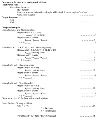
In Figure 8, pseudocode is presented for our heuristic approach to finding these variables. The total process time to manufacture the sheet metal component is represented by the variable T. This time is calculated by cumulatively adding the times for all individual operations as described below. Variable “setup time” (Fig. 8, lines 3, 6, and 9) is used to represent the time to transfer the component from a previous station to the current station. Setup time includes the time to release the component from a previous station (which will be zero for the first operation), move it to the current station, and secure it on that station. In a common large-scale production unit, the setup time can be approximated as 5–7 s for one operation. Variable torient (Fig. 8, lines 4, 7, and 10) is used to represent the time spent to prepare the component for operation in a new orientation. For example, in order to make a slit or a notch at a new location on the component, one must rotate it so that it is accessible for the current arrangement of the tooling. The variable orientation time (torient) can be approximately taken as 4–6 s for one operation. Finally, the variable operation time (toperation) (Fig. 8, lines 5, 8, and 11) represents the actual operation time (e.g., slitting, notching, shearing, bending). This time mainly depends upon the material properties of the sheet metal, the feed rate of the machine, and the area to be sheared off in the case of slitting, notching, or shearing or the angle of the bend in the case of bending.

The pseudocode for the algorithm to estimate time and cost for each grammar rule.
Consider the example of applying a notching rule. If the operation just before this operation is not another notching operation, a predetermined setup time is added to T (Fig. 8, line 6). Similarly, a predetermined torient is added to T to take into account the time elapsed to perform the operation in some other orientation (Fig. 8, line 7). Finally, the actual toperation is added to T (Fig. 8, line 8).
Based on the amount that the sheet metal area is cut or bent, an approximation of the energy consumed can be found. This also depends upon the component material properties and the dimensions of the cut or notch. It is therefore important that forces throughout the execution of rules be identified. These forces for each rule are not added like time; rather, it is important to note the highest force for the whole process to determine the operating ranges required of the machines.
Based on the rule number, dimensions instantiated for the rule (length, width, depth, location, angle of bend, etc.), and component material, we can estimate the applied force and the resulting energy provided. The work done by the process is found by integrating the force over the distance traveled.
In shearing, notching, and slitting operations, the maximum force, Fmax, required is estimated based on Kalpakjian (1992) as

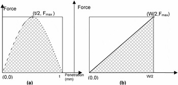
where UTS is the ultimate strength of the material, t is the thickness of the sheet metal, and L is the total length of the material sheared. Work done in these cutting operations is approximated by the parabolic curve shown in Figure 9a. At the beginning, the tool experiences no force until it contacts the material, then reaches a peak midway through the depth. From that point, less force is required to finish the cut. The energy consumed in this operation is approximately


Work or energy is represented by the area under the force curve for (a) punch-penetration curve in cutting and (b) force variation over die opening in bending.
In bending operations, force increases monotonically from when the tool contacts the sheet to when the sheet is completely bent (Fig. 9b). Again, the maximum force in this operation is estimated from Kalpakjian (1992) as

where k is a correction factor based on the type of die (0.3 is used here, which is standard for wiping dies), Y is the yield strength of the material, L is the length of the bend along the sheet, and d is the distance between the dye contact points. In estimating the work done in this operation, we assume the change in the applied force to be linear, thus:

Work is typically done over half the distance of the contact points, hence the d/2 term.
Cost of the total process is roughly based on the amount of energy required and the amount of time spent on the whole operation. The operating cost of the manufacturing plant (excluding labor and maintenance) depends upon the number of components produced per unit time that is a further function of the time required to produce a single component and the amount of energy spent or work. In the future, we propose to supplement the tool with data look-up tables from which the material properties for a particular class of tools, such as feed rates for standard machines for standard shearing operations, are selected automatically.
6. EXPERIMENT AND RESULTS
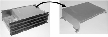
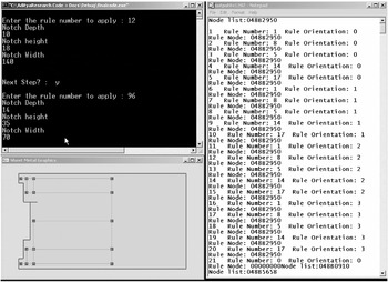
An experiment that validates the method established in Sections 3 and 4 was carried out on the top panel for the 5TI-Sequencer shown in Figure 10. The set of rules described in Appendix A was used to represent the process path for manufacturing the component. Figure 11 shows a screenshot of the actual human–computer interaction for constructing the panel using the grammar rules. As in most cases, the application of a rule starts with a seed node of a rectangular sheet metal plate having certain dimensions.

The 5TI-Sequencer has a case constructed of several sheet metal components, as well as extruded heat sinks. In this experiment, we are examining the top cover.

A screen capture for the design of the top panel of the 5TI-Sequencer.
The screenshot in Figure 11 was taken after three grammar rule operations had been completed: two side notches and one slitting operation. The rightmost window displays the rules that are applicable at any one time. As stated earlier, the recognition function “recognizes” the rules that are applicable on a particular shape. Each rule choice (1, 2···21) is associated with a grammar rule number and a unique orientation at which that rule can be applied. The rightmost window presents the user with the list of new possible operations. The dialog box in the upper left corner is the interface between the designer and the application. For example, to manufacture a side notch using grammar rule 8 on the westerly edge of the sheet metal, one must chose rule choice 12 from the list on the right. Grammar rule 8 is a 3 degree of freedom rule (Table 1) and thus requires the instantiation of three parameters: notch depth, height from top, and width. In the upper left window, the rule is instantiated with the appropriate dimensions as described in Section 4.2. Application of a rule results in a new graph structure and thus a new list of applicable rules. A graphical representation of the node structure and the current state of the design is automatically generated to provide the designer with a visual feedback of the impact of his/her decisions on the design process.
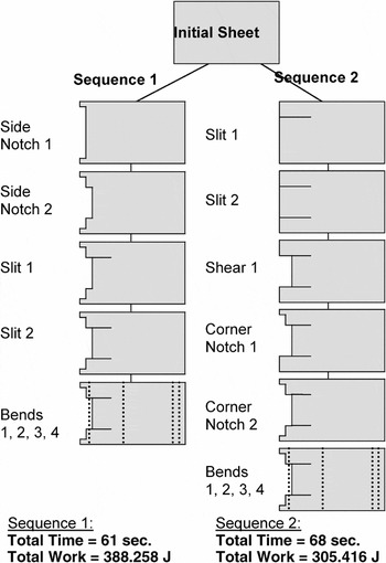
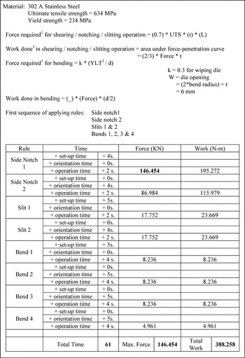
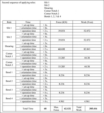
Figure 12 shows the manufacturing operations for a TI5 panel with two possible manufacturing sequences. This final shape certainly can be obtained from the given initial shape in several different ways. Time and work calculations are determined for the two sequences shown in the figure. The details of these predictions are shown in Figures 13 and 14 for Sequences 1 and 2, respectively.

A step by step comparison for manufacture of the same component by two different sequences of operations.

The time and energy calculations for sequence 1 in Figure 12.

The time and energy calculations for sequence 2 in Figure 12.
It is evident from the calculations above that the time and cost depend upon the sequence of operations performed. Different process times and energies are obtained for different sequences of operations. Hence, deciding the optimal sequence of operations for any given product is a primary challenge in reducing the time and cost of the total operation.
Figures 13 and 14 show that the time required for the first sequence (61 s) is less than that for the other (68 s). However, the amount of work required in the prior case (388.258 N m) is more than that in the later case (305.416 N m; see bold numbers). Figures 13 and 14 lead us to some interesting conclusions. Sequence 1 has many steps in which large chunks of material are removed in a single operation compared to the second sequence. In addition, large cut lengths were taken in the pieces of sheet metal that were finally scrapped. The large cutting operations are reflected in the large maximum force whereas the extra cutting operations are reflected in the extra amount of work required. Thus, sequence 1 requires more time but less work. This trade-off may not always be present. The challenge is to find an optimal sequence of operations that has both less process time and less energy required.
7. CONCLUSIONS AND FUTURE WORK
We have presented a formal approach to the design of sheet metal parts. Many of the inherent constraints in sheet metal design have been included in the grammar to prevent the system from exploring infeasible designs. The implementation is a first step in automating the complexities of sheet metal design. Determining a useful and formal representation of sheet metal components has been an important hurdle that we successfully crossed during the course of this research. The implementation and application of this representation have also been challenges that we successfully negotiated.
In the last section, we demonstrated that our implemented sheet metal grammar has proven to be successful in a real world application. In the discussion on recognition, a user or possibly a computational decision maker is presented with a number of choices of where to apply specific rules. A sheet metal part can be manufactured from a series of operations wherein the order of such operations is not unique. Following a different series of operations to make a specific design may result in a change in the design quality or the cost and speed of the manufacturing process plan. The process chosen for manufacturing a sheet metal component should be such that it requires less time and also has fewer energy requirements. However, the two requirements do not usually go hand in hand. In many situations (such as the example problem above), a compromise has to be made between these two important parameters. By linking these methods to an optimization routine, we hope to find optimal sequences of operations for minimizing both time and energy. One rule of thumb to note from this experiment is that cuts made into regions that will eventually be scrapped lead to excessive energy requirements and should be avoided. In addition, one should be wary of taking large cut lengths at a time because these operations require large forces; however, such operations do take less processing time.
In future work, the user will ideally only have to input the initial dimensions of the sheet and the final shape that he/she desires for the component. The system will then search for an optimum sequence of rules to reach the goal. This will make the whole system more user friendly, in addition to classifying it as a scenario 5 grammar under Chase's (1998) model. Furthermore, we will be exploring approaches in which the user inputs only the functionality of a required component and the automated design process will determine both the part shape and the steps required to construct that shape.
Representation of stamping operations is another avenue for future research. We have looked into the possibility of representing a stamped sheet as a grid or mesh of B-spline curves. Current work in the area of representation of curved surfaces deals with tool surface discretization (Khaldi et al., 1996), where the curved tool surface is discretized into patches using a surface discretization model. Similar work (Aberlanc et al., 1996) deals with simulated forming of sheet metal using the software OPTRIS and its pre- and postprocessor FICTURE. Building upon the shape grammar foundation presented here, advances such as these are important steps in improving the efficiency and effectiveness of sheet metal component design.
APPENDIX A
In this section, we present a brief overview of the rules that have been developed and implemented. Currently, the 17 rules fall into the categories of slitting, notching, shearing, or bending operations. Each rule is shown being applied to an eastwardly free edge; however, each rule can be applied in any of the four orthogonal operations. In some cases (as in rule 2), the rule can also be reflected so that two rule applications exist for each rotation.
A1. Slitting
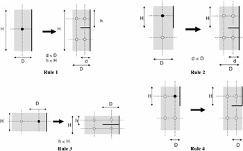
Rules 1–4 are the rules for slitting (Fig. A1). These rules define the slitting operations that can be done on any given sheet metal plate.

Slitting rules 1–4.
Rule 1: This is a simple slitting rule in which a single node results in the formation of four nodes upon completion of the slitting rule.
Rule 2: In this slitting rule, the height or position of the slit occurs between the two nodes but the depth remains variable.
Rule 3: In this case the slit is made through the entire width of the easternmost node. However, the user determines the position of the slit.
Rule 4: This is a rule in which four nodes in the pattern shown below must exist. It results in a slit of predetermined size to be formed between the easternmost nodes. The application of this rule does not require the user to choose any dimensions.
A2. Notching
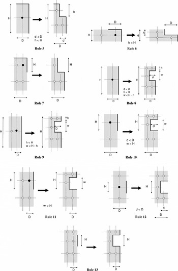
Rules 5–13 are rules for performing the notching operation on a sheet metal component (Fig. A2).

Notching rules 5–13.
Rule 5: This is a corner notching rule, which results in the production of a corner notch.
Rule 6: The sixth is a corner notching rule applied on two adjacent nodes, which leads to the production of a notch having a width equal to the width of the corner node.
Rule 7: In this rule, four nodes in the pattern shown below must exist. The node on which this rule is applied must be a corner node. It results in the deletion of the corner node.
Rule 8: Rule 8 is the side notching rule, which results in the formation of five nodes from one node and leads to the production of a side notch.
Rule 9: This rule transforms two nodes into five nodes with the depth of the notch being equal to the width of the edge node.
Rule 10: In this rule the position of the notch is fixed, but its depth and width can be varied.
Rule 11: The following rule is similar to rule 10; however, the only variable is notch width, keeping position and depth constrained.
Rule 12: In this case, the position and the width are constrained and the depth can be varied.
Rule 13: This is a rule in which six nodes in the pattern shown below must exist. Here again, the resulting nodes are unchanged from the left-hand side. The only difference is the deletion of the central eastern node.
A3. Shearing
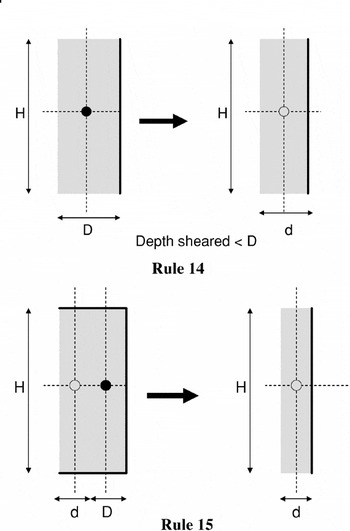
Rules 14 and 15 are shearing rules (Fig. A3).

Shearing rules 14 and 15.
Rule 14: This rule is a simple shearing rule in which a length specified by the user is sheared from the current node. In order to perform this operation, three sides of the node must be edges.
Rule 15: This is a rule in which the node on which the rule is applied is deleted, being effectively sheared by a distance equal to the width of the node.
A4. Bending
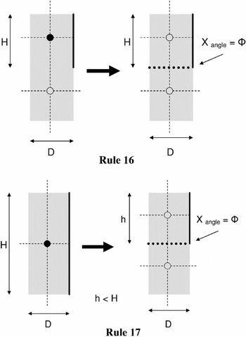
Rules 16 and 17 are bending rules (Fig. A4).

Bending rules 16 and 17.
Rule 16: This bend rule applies between two existing nodes. The only change is the addition of a bend angle that propagates to neighboring nodes, preventing them from being bent in the orthogonal direction. An angle (Φ) has to be instantiated by the user.
Rule 17: Rule 17 splits a single node with a bend at both a specified height of position and a bend angle. Here, the position, as well as the angle, have to be input by the user.
References
REFERENCES
Aberlanc, F.,
Babeau, J., &
Jamet, P.
(1996).
OPTRIS: The complete simulation of sheet metal forming.
Sheet Metal Stamping for Automotive Applications, SAE Int.
Congress.
Boothroyd, G.,
Dewhurst, P., &
Knight, W.
(1994).
Product Design for Manufacture and Assembly.
New York:
Marcel Dekker.
Bourne, D. &
Fussel, P.
(1982).
Designing Programming Languages for Manufacturing Cells.
Technical Report CMU-RI-TR-82-05.
Pittsburgh, PA:
Carnegie Mellon University, Robotics Institute.
Brown, K.N. &
Cagan, J.
(1997).
Optimized process planning by generative simulated annealing.
Artificial Intelligence in Engineering Design, Analysis and
Manufacturing
11,
219–235.Google Scholar
Cagan, J.
(2001).
Engineering shape grammars. In
Formal Engineering Design Synthesis
(Antonsson, E.K. &
Cagan, J., Eds.).
New York:
Cambridge University Press.
Cagdas, G.
(1996).
A shape grammar: The language of traditional Turkish houses.
Environment and Planning B: Planning and Design
23,
4.Google Scholar
Chappuis, L.,
Tang, S.,
Chen, X., &
Wu, J.
(1993).
A numerically stable computer model for sheet metal forming analysis
by 2D membrane theory.
SAE International SP-944.
Sheet Metal and Stamping Symp.
Chase, S.C.
(1998).
User interaction models for grammar based design systems.
International Journal of Design Computing
1.
Available on-line at
http://www.arch.usyd.edu.au/kcdc/journal/vol1/dcnet/stream4/paper2Google Scholar
Cheng-Hua, W. &
Bourne, D.
(1995).
Design and manufacturing of sheet metal parts: Using features to
aid process planning and resolve manufacturability problems. In
Computers in Engineering 1995
(Busnaina, A., Ed.), pp.
745–753.
New York:
ASME.
Fu, Z.,
De Pennington, A., &
Saia, A.
(1993).
A graph grammar approach to feature representation and
transformation.
International Journal of Computer Integrated Manufacturing
6(102),
137–151.Google Scholar
Gupta, S.,
Bourne, D.,
Kim, K., &
Krishnan, S.
(1998).
Automated process planning for sheet metal bending operations.
Journal of Manufacturing Systems
5.Google Scholar
Hardt, D.,
Boyce, M.,
Ousterhout, K.,
Karafillis, A., &
Eigen, G.
(1993).
A CAD-driven flexible forming system for three-dimensional sheet metal
parts.
SAE International SP-944.
Sheet Metal and Stamping Symp.
Hishida, Y. &
Wagoner, R.
(1993).
Experimental analysis of blank holding force control in sheet
forming.
SAE International SP-944.
Sheet Metal and Stamping Symp.
Kalpakjian, S.
(1992).
Manufacturing Processes for Engineering Materials,
2nd ed.
New York:
Addison–Wesley.
Katayama, T.,
Yoshida T., Ohwue T., &
Usuda, M.
(1993).
Predictive evaluation of sheet metal forming limit using 3-D FEM.
SAE International SP-944.
Sheet Metal and Stamping Symp.
Khaldi, F.E.,
Bernardi, R.D., &
Ogura, O.
(1996).
Sheet metal forming: State of the art application methodology and
simulation streamlining.
Sheet Metal Stamping for Automotive Applications, SAE Int.
Congress.
Klahr, D.,
Langley, P.,
Neches, & R.,
Eds.
(1987).
Production System Models of Learning and Development.
Cambridge, MA:
MIT Press.
Koning, H. &
Eizenberg, J.
(1981).
The language of the prairie: Frank Lloyd Wrightís prairie
houses.
Environment and Planning B: Planning and Design
8,
295–323.Google Scholar
Lascoe, O.D.
(1988).
Handbook of Fabrication Processes.
Metals Park, OH:
ASM International.
Li, X.,
Schmidt, L.,
He, W.,
Li, L., &
Qian, Y.
(2001).
Transformation of an EGT grammar: New grammar, new designs.
DETC2001/DTM-21716.
Proc. ASME 2001 Design Eng. Tech. Conf.,
Pittsburgh, PA.
Lin, Z.C. &
Hong, J.T.
(1998).
Sheet metal products: Database in support of their process planning
and surface development.
International Journal of Computer Integrated Manufacturing
11(6),
524–533.Google Scholar
Lipson, H. &
Shpitalni, M.
(1997).
On the topology of sheet metal parts.
Transactions of the ASME Journal of Mechanical Design
120(1),
10–16.Google Scholar
Longenecker, S.N. &
Fitzhorn, P.A.
(1991).
A shape grammar for non-manifold modeling.
Research in Engineering Design
2(3),
159–170.Google Scholar
Mitchell, M.
(1996).
An Introduction to Genetic Algorithms.
Cambridge, MA:
MIT Press.
Pinilla, J.M.,
Finger, S., &
Prinz, F.B.
(1989).
Shape feature description using an augmented topology graph
grammar.
Proc. NSF Eng. Design Res. Conf., pp.
285–300.
Amherst, MA, June 11–14, 1989.
Shpitalni, M. &
Lipson, H.
(2000).
3D conceptual design of sheet metal products by sketching.
Journal of Materials Processing Technology
103(1),
128–134.Google Scholar
Stiny, G.
(1980).
Introduction to shape and shape grammars.
Environment and Planning B: Planning and Design
7,
343–351.Google Scholar
Wang, C.H. &
Sturges, R.H.
(1996).
BendCad: A design system for concurrent multiple representations of
parts.
Journal of Intelligent Manufacturing
7(2),
133–144.Google Scholar
The generic flowchart for a search process has four basic tasks: representation, generation, evaluation, and guidance.
The current sheet metal grammar is at scenario 4, where the computer determines the object and the matching conditions (recognition and application of rules).
An example sheet metal component represented by three nodes.
The four basic sheet metal operations: notch, shear, stamp, and bend. The arrows represent the ideal flow of operations. For example, bending should follow notching but not vice versa.
An example sheet metal component. (a) The component is a small bracket for supporting shelves. (b) A close-up of the end shows how bends and slits are arranged. (c) The grammar works by starting with a single blank upon which rules are applied to create the final shape.
Within the context of a computational design synthesis process shown in Figure 1, the grammar presented in Section 4 is an inner loop to the task of generating new designs.
Grammar rules with respective degrees of freedom (DOF)
Rule 1 causes a slit that splits a single node into four nodes. This requires some dimensions to be specified (height, notch width).
The pseudocode for the algorithm to estimate time and cost for each grammar rule.
Work or energy is represented by the area under the force curve for (a) punch-penetration curve in cutting and (b) force variation over die opening in bending.
The 5TI-Sequencer has a case constructed of several sheet metal components, as well as extruded heat sinks. In this experiment, we are examining the top cover.
A screen capture for the design of the top panel of the 5TI-Sequencer.
A step by step comparison for manufacture of the same component by two different sequences of operations.
The time and energy calculations for sequence 1 in Figure 12.
The time and energy calculations for sequence 2 in Figure 12.
Slitting rules 1–4.
Notching rules 5–13.
Shearing rules 14 and 15.
Bending rules 16 and 17.
 You have
Access
- 6
- Cited by