1. INTRODUCTION
Low-cost, quickly manufactured housing is a critical need in developing parts of the world, in rural or underserved communities, and in postdisaster environments. Innovative solutions for new or replacement homes (or other small buildings such as schools, stores, and medical centers) in developing or devastated areas are a high global priority. Developing communities often have strong visual, vernacular design traditions. These design traditions are expressed through decoration, shape, and form, and are embedded in artifacts at all scales from utensils to clothing to houses. Shared values, beliefs, customs, and practices are communicated through these design traditions. They have important cultural and social functions that promote community identity. Too often, though, low-cost, prefabricated, or emergency housing solutions are generic and bland, ignore local design traditions, and are devoid of cultural sensibility.
This paper introduces a new line of research that seeks to develop low-cost, high-quality, mass customizable building assembly systems that express vernacular or location-specific visual design languages. The building systems would provide the structural envelopes for houses or other small structures. Design customization in these building systems is intended to occur on two levels. First, a building system would be customized for a particular culture or community by incorporating a traditional or other familiar visual language into the design and assembly of building components. Second, building components within a system could be assembled in different ways to express, as part of wall structures, different pattern variations within a visual language. Mass customization of the overall shape and physical form of houses is also a possibility, but it is not the emphasis of the research here (for work along these lines, see Sass & Botha, Reference Sass and Botha2006). An important intent here is to think beyond ornament and decoration as surface treatment on buildings or as a byproduct of structure, and to think instead of a visual language as an integral part of the logic of a building assembly, even as a driver of the design of a building assembly. An allied goal of this research is to empower local communities by engaging them in the design of building assembly systems, and in the on-site construction of their homes. The long-term research ambition is to develop new kinds of formal, visual–physical design grammars that specify complete, full-scale visual and physical details of assembly systems. In other words, the rules of these grammars would apply to generate computer-assisted design/computer-assisted manufacturing (CAD/CAM) data for machine fabrication of components for assembly design variations.
Advanced computational theories and technologies are integral to this research. The visual, aesthetic aspects of the research are explored through the use of shape grammars. Shape grammars are generative, rule-based systems for describing and generating languages of visual or spatial designs, that is, sets of design alternatives embodying a particular style (Knight, Reference Knight1999). They are ideal for capturing the visual or decorative features of vernacular traditions and encoding these features in building assemblies. The physical design and manufacturing aspects of the research are explored through the use of advanced digital design and fabrication tools and technologies. Digital design and fabrication technologies provide the foundations for the structural and material aspects of assembly designs. In particular, the assembly systems proposed here draw on recent work on monomaterial assemblies with interlocking components that can be fabricated with computer numerical control (CNC) machines and assembled by hand on-site (Sass, Reference Sass2008). Beyond the specific context of housing and building assemblies, the proposed research has the potential to impact the design and manufacture of designed artifacts at many scales and in many domains, especially in domains where visual aesthetics need to be considered jointly with physical, structural, or material requirements, and where design customization and variation is important.
This paper reports on the first phase of this new research endeavor: pilot studies exploring the possibilities of combining shape grammars and digital fabrication in the design and prototyping of assembly systems, undertaken in the Department of Architecture at the Massachusetts Institute of Technology (MIT). The studies began with vernacular design languages from different regions of the world, and shape grammars for understanding and generating these languages. The end products of the studies were assembly systems for desktop-scale wall sections prototyped using a layered manufacturing machine [three-dimensional (3-D) printer], a first step toward assembly systems for full-scale, 3-D building enclosures. The desktop systems revealed structural and material problems that would need to be resolved for full-scale systems. Nonetheless, the results overall were very promising, and most significantly, demonstrate a spectrum of strategies for embedding visual properties in structural systems, strategies that may be generalizable across different visual design languages. One pilot study is currently being developed further for a full-scale prototype. The results of the preliminary studies are overviewed in this paper, and important next steps toward the longer term research objectives are outlined. The foundations for this new research in the areas of digital fabrication and shape grammars are discussed first.
2. FOUNDATIONS
The two areas of computational design brought together here have complementary research emphases. Digital fabrication research focuses on the physical aspects of designs, including ways to digitally model designs for physical manufacture with computer-controlled machines at all scales: from desktop models to full-scale buildings. In contrast, work with shape grammars focuses mostly on the visual aspects of designs, including the computational representation and generation of styles or languages of visual designs. The benefits of bringing these two research areas into alliance to support an integrated computational design process, spanning the conceptual design stage to the construction stage, have begun to be explored in recent years (see, e.g., Sass & Oxman, Reference Sass and Oxman2005; Sass, Reference Sass2008). The work described here furthers this alliance and the joint potentials of the two research streams.
2.1. Digital fabrication
Digital fabrication for architectural design is a rapidly growing field. It combines interests in both rapid prototyping and CNC manufacturing. Many areas within engineering use digital fabrication routinely to build high-precision products from drinking cups to cell phones to cars to airplanes. Research in architecture is just beginning to investigate how computer-driven machinery can be integrated into the building construction process to produce buildings of high quality and functionality at low costs and fast production speeds.
Kiernan and Timberlake (Reference Kieran and Timberlake2003), for example, present a theoretical approach to building delivery based on computer-generated designs manufactured with machinery. Their concept is a transformation of the building manufacturing industry from artful products delivered by hand to higher quality machine-manufactured artifacts. They contrast current building delivery based on computer-generated designs and hand-based construction with more fully automated methods of automobile and aeronautical delivery. An early adoption of Kieran's and Timberlake's ideas is found in Contour Crafting (Khoshnevis, Reference Khoshnevis2004). Contour Crafting is one of a few flexible construction systems that can be used to build nonstandard building shapes. It is an automated wall construction system that works by deposition of liquid concrete. A major limitation is in the production of building shapes beyond funicular-like dome and vault shapes. Angular or boxlike shapes with flat or pitched roofs are complex or impossible to produce because they involve the production of overhanging elements in the making of roofs or ceilings. For the same reason, window openings and door openings are difficult to form.
An alternate approach to flexible, customized design and construction system can be found in the research work of the Digital Design and Fabrication Group (DDFG) at MIT. Much of DDFG research aims to bring the benefits of technology to the developing world, and in particular, to innovate new kinds of building assembly systems for low-cost housing. A guiding assumption in this work is that in the near future laptops and fabrication machines will be cheaper and more accessible to underdeveloped communities, opening up possibilities for inexpensive, fast, and efficient construction processes. DDFG is developing and prototyping novel component-based housing systems that can be fabricated and assembled on-site using local labor and readily available materials. Components are made of a single material, for example, plywood or concrete, and have integrated attachments so that they can be fitted and locked together manually with few tools and few additional fastening or binding materials. The use of CNC machines and new computational methods for parametric and generative design also allow for complex or unique components to be manufactured as efficiently as identical ones, making mass customization and design variation a goal of these systems. Figure 1 shows some studies of building assemblies with different kinds of attachment or interlocking features, all prototyped with a 3-D printer at desktop scale. Attachment features can be either visible or hidden when components are assembled.
Studies for building assemblies with different kinds of attachment features (Digital Design and Fabrication Group, MIT). [A color version of this figure can be viewed online at journals.cambridge.org/aie]

A key characteristic of low-cost housing with digital fabrication comes from a rethinking of assembly design with fewer small components and less or no mortar compared with legacy home construction. Assembly of parts with digital fabrication allows for high tolerances and for assemblies sustained primarily by friction. Assembly logic builds on theories developed by researchers in the field of mechanical engineering. Two areas of work are particularly relevant. One is Geoffrey Boothroyd's and others' work on “design for assembly” that considers ways to simplify the manufacture of products by reducing the number of components or parts in an assembly to a minimum (Boothroyd et al., Reference Boothroyd, Dewhurst and Knight2001). Another is Robert Messler's work on integral attachments, which were developed for the plastics industry as a way to design snap fit connections (Messler, Reference Messler2003). This work started the revolution in snap fit plastics for toys, cell phones, computers, and cars. Results in the application of mechanical engineering theories are a reduction in the number of on-site laborers and the time required for assembly. DDFG work incorporates these theories as part of the process of designing each component, with the goal of generating data for manufacturing and ease of assembly.
The structural and material performance of new digitally designed and fabricated assemblies is naturally a top priority. However, the ultimate success of these building systems in developing or traditional environments will depend as much on aesthetic appeal, visual cues, and cultural connotation as on structure and function. Their acceptance will require going beyond the generic sameness of much prefabricated housing and on not assuming contemporary Western or high-style architectural concepts and values. The importance of cultural expression in built form, indeed its priority over functional or economic considerations, has been widely studied and recognized, for example, in the well-known work of the architect and anthropologist Amos Rapoport. Drawing on numerous case studies in developing countries, Rapoport notes how “the neglect of traditional cultural patterns [in built form] may have serious results” (Rapoport, 1969, p. 129). Regard for local, vernacular traditions is especially important for postdisaster or relief housing which, if designed by outside agencies for physical shelter alone, is often rejected by the local community (Oliver, Reference Oliver2006, pp. 183–263). The assembly systems described here do not attempt to integrate all possible culture-driven characteristics of built form, characteristics that might include anything from site layout to construction materials. Only the visual appearance of the structural envelopes and walls of houses are considered. Still, this is a significant step toward incorporating cultural factors in new ways of designing and building.
Happily, the CAD/CAM technologies that make new, digital assembly systems possible also afford opportunities for incorporating aesthetic and culturally relevant elements directly into the design and fabrication of customized components. Indeed, the recent resurgence of interest in architectural ornament and decorated building surfaces is in large part due to the increasing availability of digital fabrication devices (Abruzzo & Solomon, Reference Abruzzo and Solomon2006; Moussavi & Kubo, Reference Moussavi and Kubo2006). Complex and variable decorative forms can be digitally machined easily and accurately. At the same time, new algorithmic techniques for visual or spatial design, in particular, shape grammars (Stiny & Gips, Reference Stiny, Gips and Freiman1972), enable the conceptualization and generation of rich and varied languages of designs. Shape grammars make possible a mass customization of visual/spatial design similar to the mass customization in building construction offered by CAD/CAM technologies.
2.2. Shape grammars
Shape grammars were one of the first computational design systems to be wholly visual, and they remain distinctive for their visual approach (Stiny, Reference Stiny2006). Shape grammars compute directly with shapes in two or three dimensions, rather than with symbols, words, or numbers, or other abstract structures such as graphs that represent visual shapes indirectly. A shape grammar consists of a set of rules that apply recursively to a starting shape to generate designs in a language. Shape grammars have been used for two complementary and overlapping design activities: original design and analysis. Across these two areas, they have been applied in virtually all areas of design from architecture to landscape design to furniture design to painting to product design to mechanical design.
In original design applications, shape grammars are developed from scratch to generate completely new and original designs, and have been used in architectural design and teaching (Knight, Reference Knight and Schmitt1992, Reference Knight1999). In analysis applications, shape grammars are developed for existing design languages, styles, or brands, as a way of capturing and representing design knowledge and understanding of these languages. In architecture, for example, shape grammars have been developed to identify the compositional principles underlying historic styles such as Palladian villas (Stiny & Mitchell, Reference Stiny and Mitchell1978). In engineering design, they have been used to capture and deploy expert design knowledge, for example, in the design of microelectrical–mechanical systems resonators (Agarwal et al., 2000). In product design, they have been used to characterize brand identity, from the brand identity of Harley–Davidson motorcycles (Pugliese & Cagan, 2002) to those of top-name coffee maker designs (Agarwal & Cagan, Reference Agarwal and Cagan1998).
In analytic work of this kind, grammars are developed through a careful examination of an existing corpus of designs. The rules extracted from the original designs are simultaneously descriptive, generative, and predictive. The rules describe the compositional structure of the original designs: both the recurring visual or spatial elements and the ways the elements are combined. They generate the original designs and they generate and predict new, hypothetical designs like the original ones. Shape grammars may also be defined parametrically, thus including the notion of parametric design. Because shape grammars are visual, they are especially well suited for analysis. Shape rules convey the characteristic 2- or 3-D features of design languages much more directly and succinctly than other symbol- or text-based generative design systems (e.g., systems specified with computer programs or scripts). In other words, the medium for analysis with shape grammars (visual or spatial rules) is the same as the medium of the objects of analysis (visual or spatial artifacts).
For the same reason, shape grammars are also well suited for communicating the principal features and possible design variations within a vernacular language, and as the starting point for encoding these features and variations in a building assembly system. Several shape grammars for vernacular styles have been developed over the years, although these are mostly for styles of architectural design, not decorative design such as the ones considered in this paper. They include grammars for traditional architecture from Japan (Knight, Reference Knight1981), Taiwan (Chiou & Krishnamurti, Reference Chiou and Krishnamurti1995), Turkey (Cagdas, Reference Cagdas1996), China (Li, Reference Li2002), and Bosnia (Colakoglu, Reference Colakoglu2005). In these grammars, specific rules for visual or spatial features of designs often correlate with cultural factors. Notably, in the grammar for traditional Taiwanese dwellings, shape rules are defined from traditional construction processes that are strongly tied to cultural beliefs and values. For example, the beginning rules of the grammar, which set the basic dimensions of a building, reflect key cultural principles of feng-shui (Chiou & Krishnamurti, Reference Chiou and Krishnamurti1995, p. 693). In related work by Askowan and Cagan (Reference Asokan and Cagan2005), shape grammars are used in conjunction with other kinds of grammars, called movement grammars, to elucidate how cultural factors constrain the movement and interaction of people and influence the form of traditional artifacts.
3. PILOT STUDIES
The pilot studies for building assembly systems described here were done as short, 3-week student projects under the direction of the authors. The goal of each study was twofold: physical and visual. The physical goal was to design and prototype a building assembly system for a wall section. The visual goal was to integrate a vernacular design language into the building system so that different arrangements of building components would lead to different visual designs in the language.
Three different vernacular languages formed the basis of these studies: kolam designs from India, litema designs from South Africa, and meander designs from Greece. Shape grammars were defined for each language (by Knight). Students selected a shape grammar with which to work. Thus, they began with a specific interpretation of the basic visual elements or motifs of a language and the ways they combine to make design variations. The challenge was to interpret or rerepresent the 2-D visual elements and rules of the shape grammar as 3-D physical components and assembly methods for a building system. The responses to this challenge varied, revealing different possible strategies for translating a visual language into a physical building system. Visual elements were expressed through the overall shape, detailing, and/or color of building components. Interlocking or attachment elements sometimes served as visual elements as well as structural ones.
The pilot studies based on the kolam, litema, and meander languages are described in turn in the next three sections. Each section begins with brief descriptions of the vernacular language and the shape grammar for it, followed by the interpretation of the grammar as a wall assembly system.
3.1. Kolam designs
Kolam are traditional, ritualistic patterns made in India, in the southeastern state of Tamil Nadu. They are traditionally made by women on the thresholds of their homes. They are made daily, early in the morning. After they are completed they are meant to be walked on, so that by the end of the day they are worn away. For special occasions, kolam patterns can be very elaborate and may extend up the sides of houses. Traditional kolam are abstract, but many contemporary patterns include representational or figurative elements.
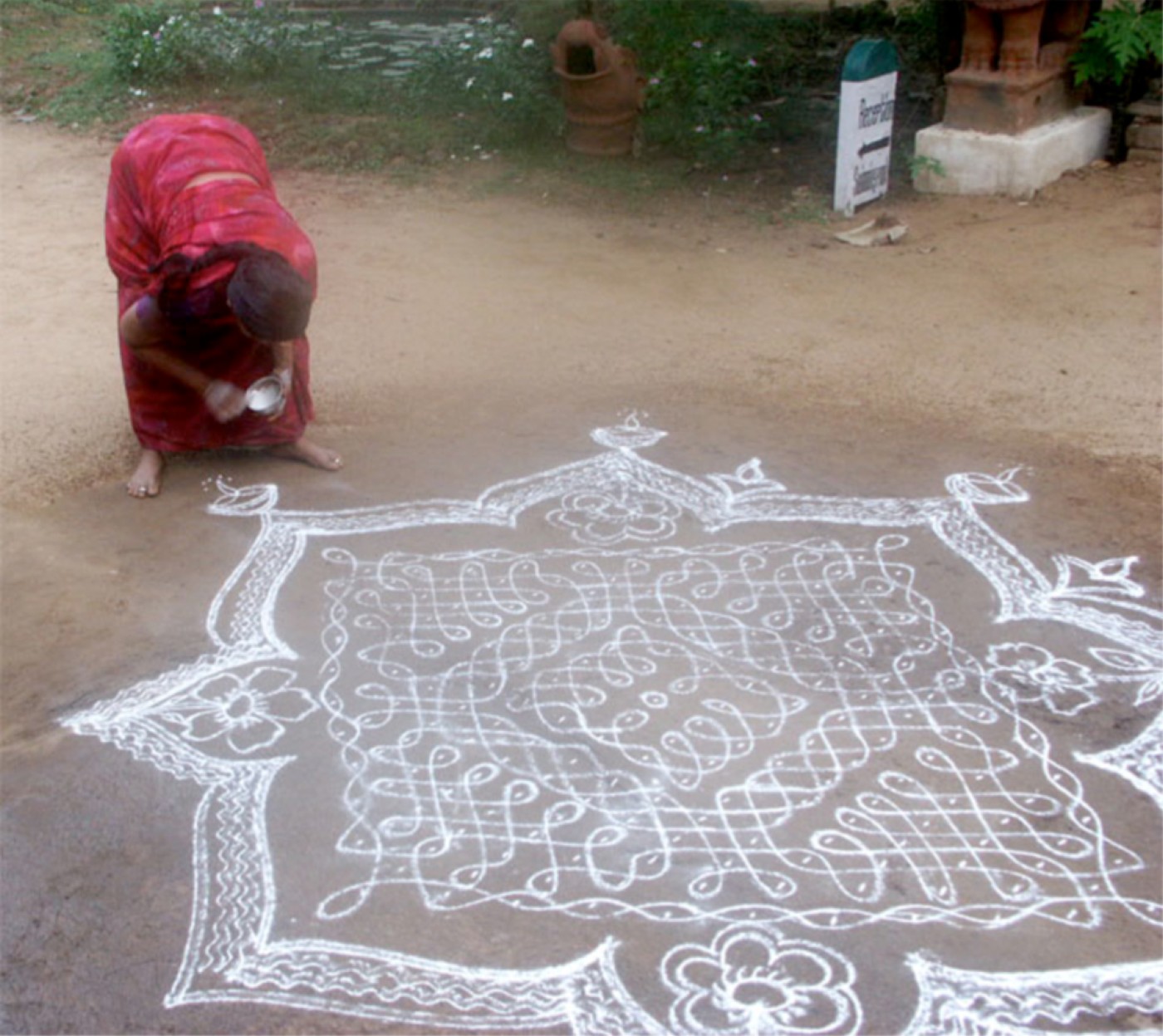
Kolam designs are made from finely ground rice powder that is trickled from between the fingers in a thin stream onto the ground (Fig. 2). First, a grid of dots is laid out on the ground, usually a regularly spaced symmetric grid. Then the rice powder is laid out to form a line that circles around the dots, intersecting itself repeatedly. Some kolam are formed with one continuous self-intersecting curve that ends where it begins; others with multiple continuous curves. Kolam are rich with aesthetic and cultural significance. They are ritual markers of the space between public and private worlds, they pay homage to the goddess of the earth and good luck, and they are tied to various other value and belief systems.
Creating a kolam design. Retrieved May 28, 2008, from http://www.tamilnation.org/culture/kolam.htm. [A color version of this figure can be viewed online at journals.cambridge.org/aie]
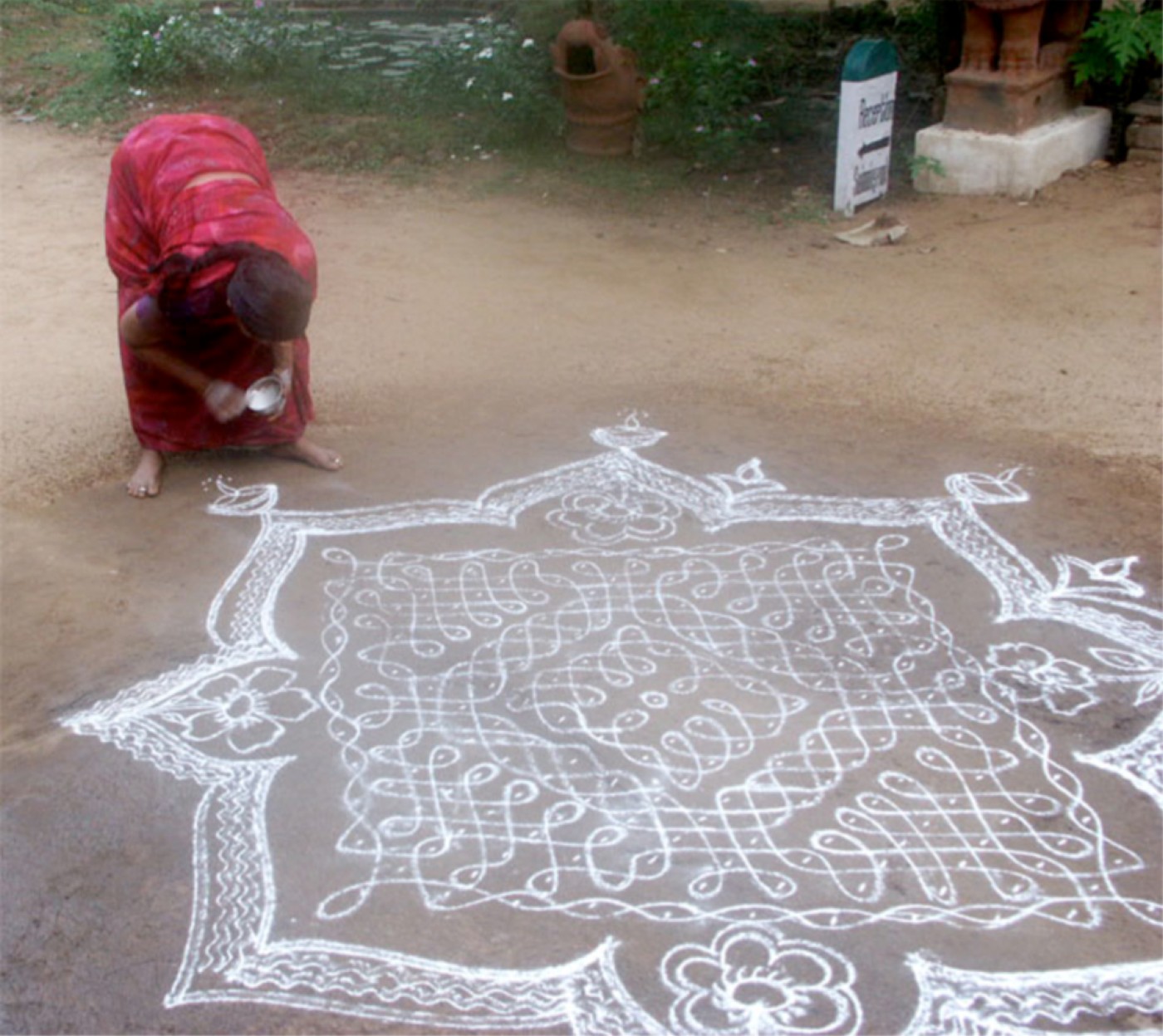
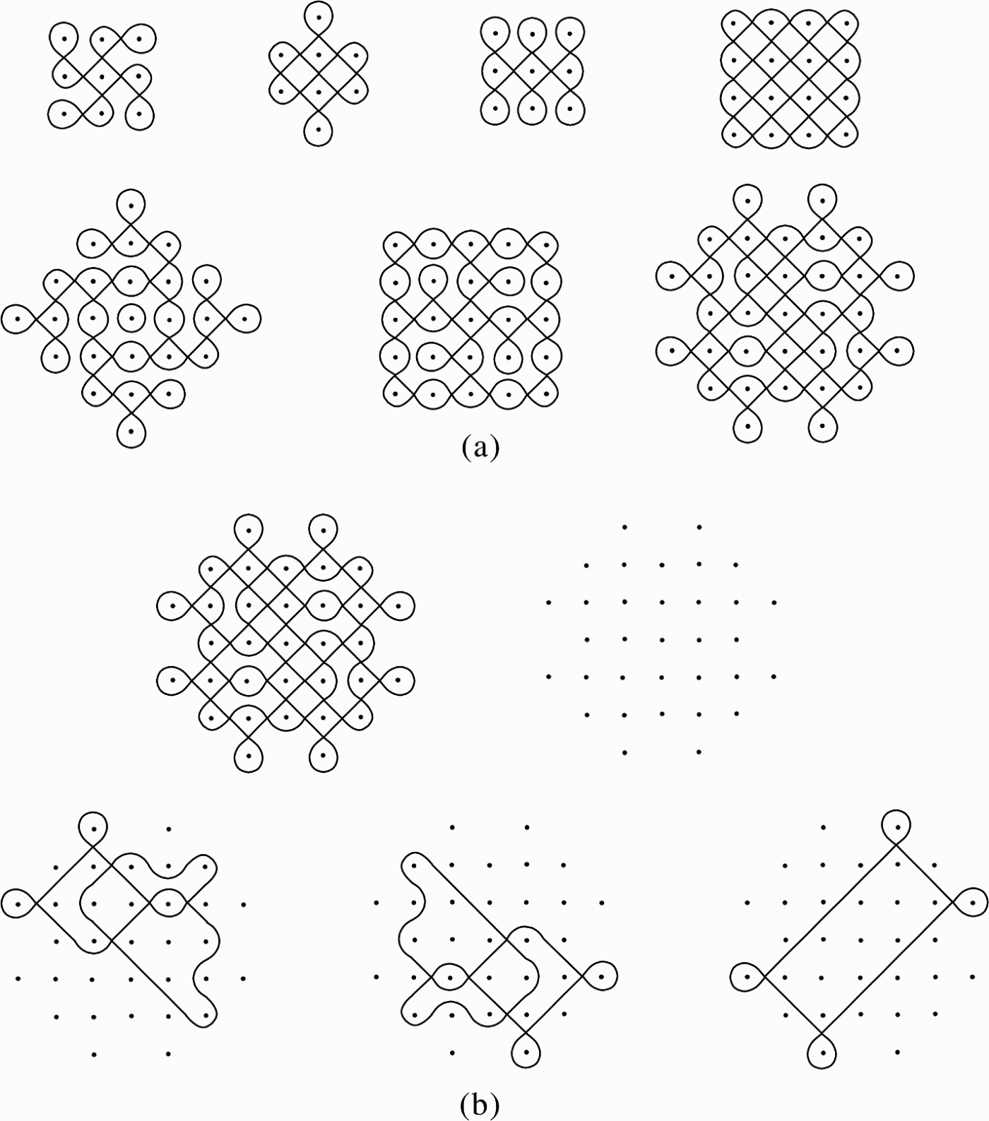
Figure 3a illustrates some traditional, abstract kolam patterns. Figure 3b shows the underlying dot or pulli grid and the continuous curves underlying one of the designs in Figure 3a. Kolam designs generally adhere to three design constraints related to symmetry, connectivity, and orientation. Designs usually have rotational or reflective symmetry as in the examples in Figure 3. Typical symmetries are rotational symmetry with a half (180°) turn or two quarter (90°) turns, or reflective symmetry across two perpendicular axes. Designs are generally of one piece, that is, they cannot be partitioned into separate patterns. In addition, designs are oriented so that the principal axes of designs are nonorthogonal with respect to the thresholds of homes. The designs in Figure 3a are all oriented in this way with respect to the boundaries of the page.
(a) Some traditional, abstract kolam patterns and (b) the underlying dot or pulli grid and the three continuous curves underlying one of the designs in (a).

The formal properties of kolam designs have attracted the attention of computer scientists and mathematicians who have analyzed the designs in terms of graphs, combinatorics, array grammars, and L-systems (e.g., see Siromoney et al., Reference Siromoney, Siromoney and Krithivasan1974; Ascher, Reference Ascher and Ascher2002; Demaine et al., Reference Demaine, Demaine, Taslakian and Toussaint2007). Narayanaswamy (online) developed a simple interactive computer program for generating kolam designs that uses a process very different from the traditional design process, but is nonetheless an effective and simple means for generating the same language of design possibilities. The shape grammar given here uses an approach similar to his.
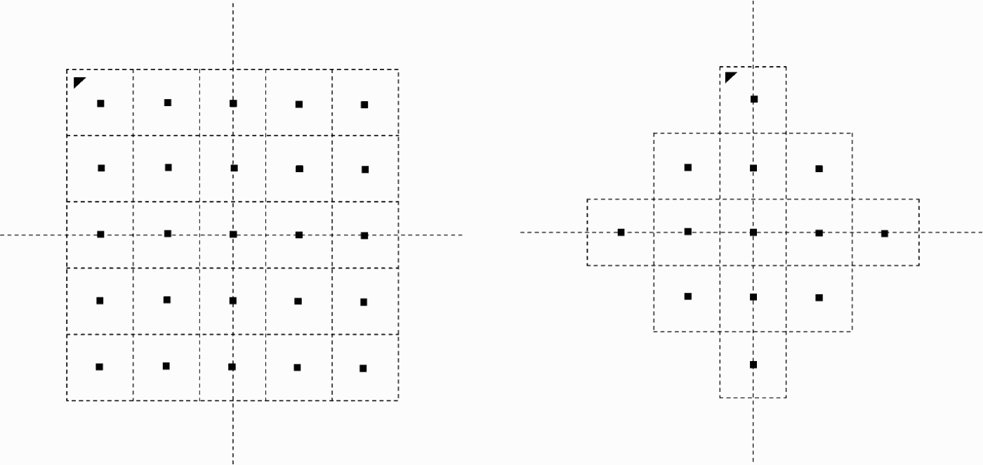
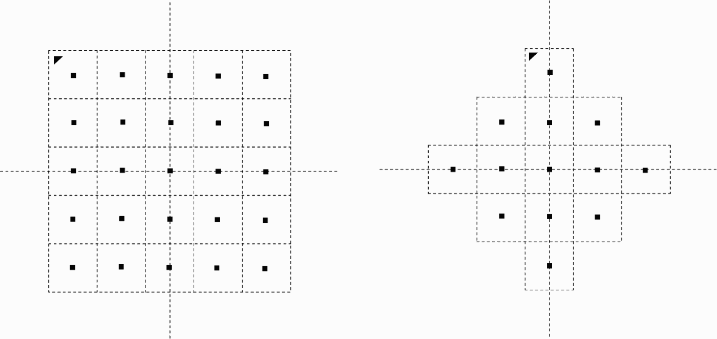
The grammar begins with a symmetrical grid of square cells. The specific reflective or rotational symmetry of the grid must be indicated in some fashion, for example, by showing the point of rotation and/or axes of reflection. Figure 4 shows two examples of possible starting grids. Both grids have reflective symmetry across the two axes shown. Each cell of a grid is marked with a square symbol denoting a pulli. One cell is marked with a triangle label explained below. The rules of the grammar place a motif within each cell of the grid. The different possible motifs are shown in Figure 5. Each motif touches the boundaries of a cell at one, two, three, four, or none of its four sides. Motifs are placed so that the vertices of motifs touch, creating continuous line patterns.
Possible starting grids for the kolam grammar.
Kolam motifs.

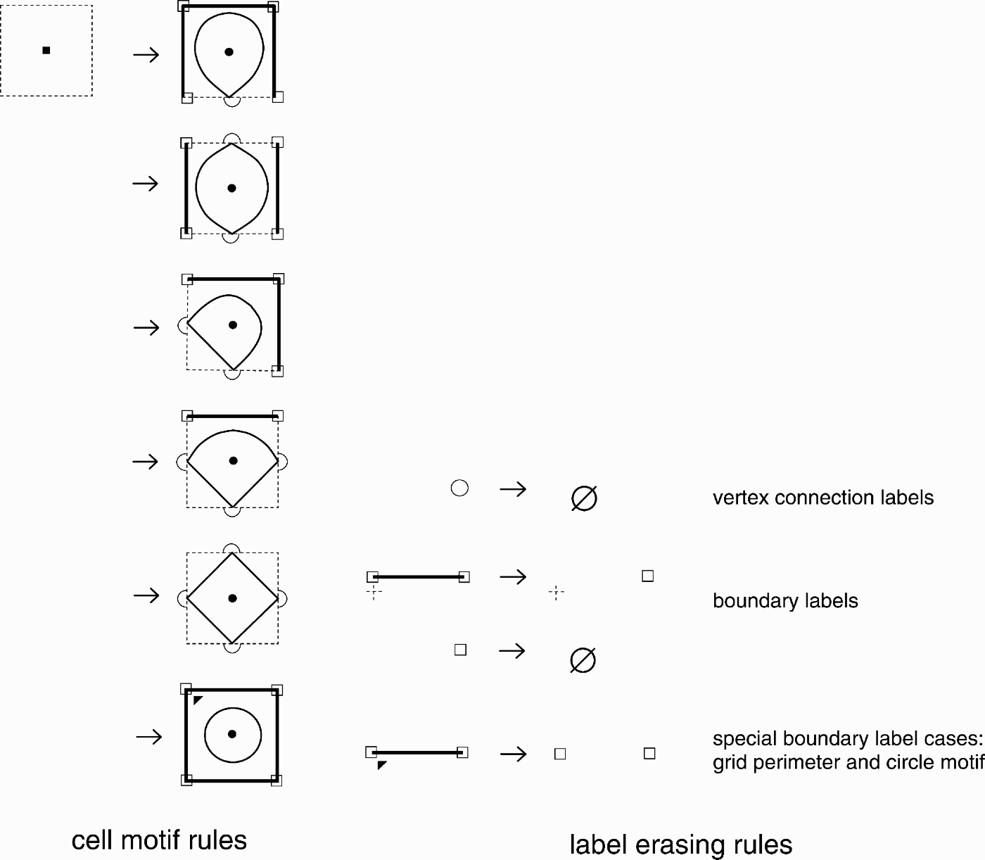
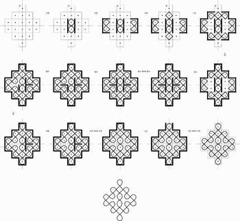
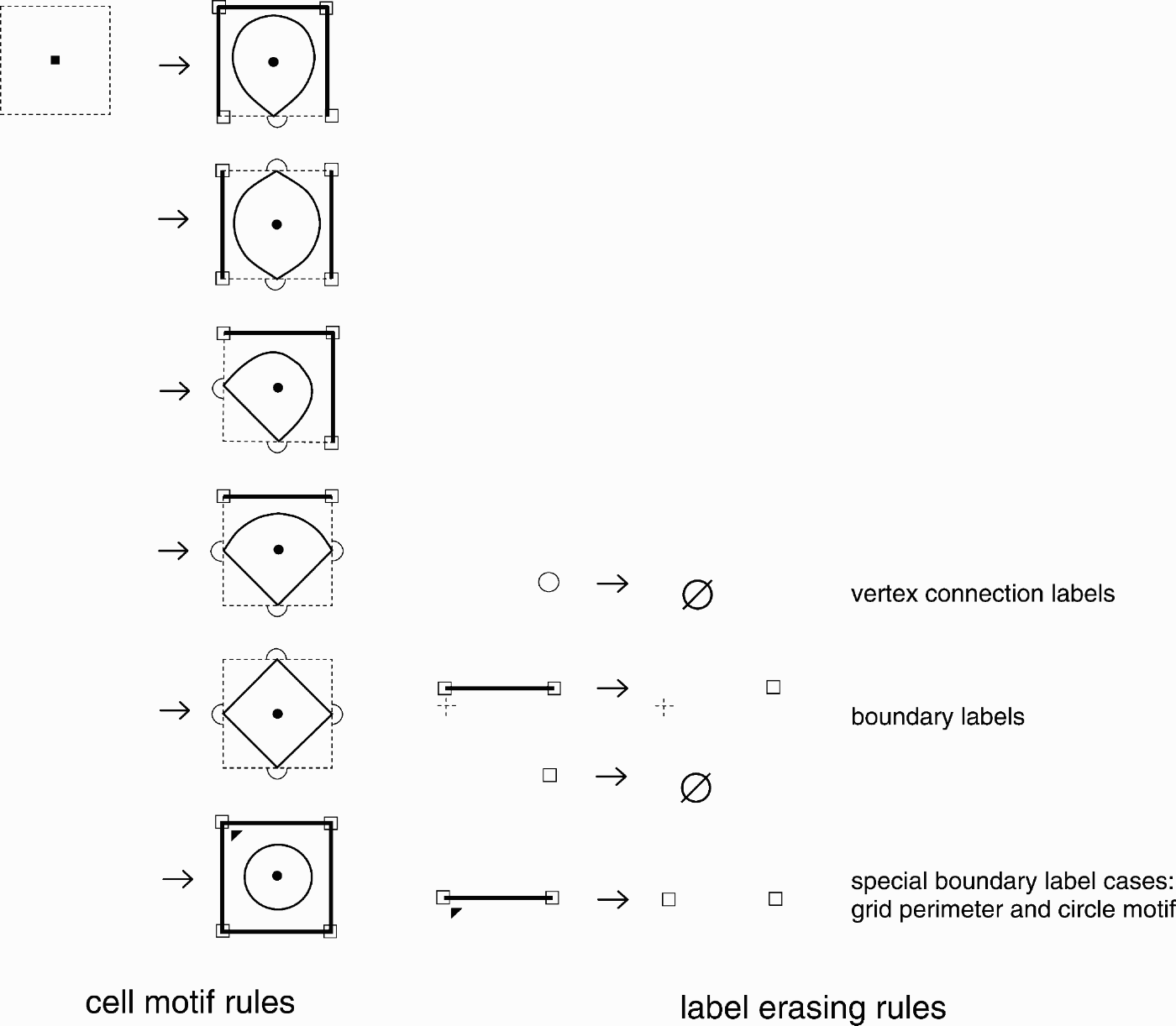
The rules of the grammar are shown in Figure 6. The motif rules apply to add motifs to each cell of an initial grid. Labels are used in these rules to ensure that they apply to generate correct kolam designs. A design is considered correct and complete only when all labels on a design have been removed by the label-erasing rules. The square label on the left side of each motif rule is replaced by a dot or pulli when the rule is applied, thus ensuring that every cell in a starting grid is replaced with a motif. The half-circle labels ensure that every vertex of an added motif connects to a vertex of an adjacent motif to generate continuous line patterns. These labels can only be erased, using the first label-erasing rule, when a complete circle is formed by two half circles. The bold lines marking the edges of cells not touched by a motif vertex, together with the square corner labels, ensure that the connectivity constraint described above is maintained. These labels can only be erased, using the second, third, and forth label-erasing rules, when a connected design is generated. The fourth rule is also used to erase a boundary label associated with the perimeter of a grid or with a circle motif (the one exception to the connectivity constraint). These special conditions are identified with triangle labels. To satisfy the symmetry constraint, rules must apply in parallel with respect to the reflection axis (or axes) or point of rotation in a starting grid. In other words, when a rule is applied to add a motif to a grid cell, then it applies at the same time to add its symmetrical counterpart to all other cells in the grid necessary to maintain the overall grid symmetry (see Fig. 7). The orientation constraint is handled straightforwardly by orienting the initial shape appropriately with respect to a threshold.
A kolam shape grammar.
Computation of a new kolam design.

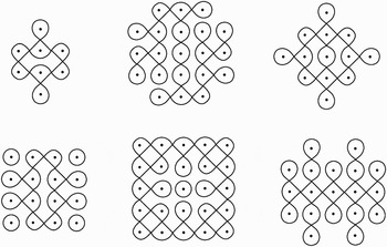
The computation of a kolam design is illustrated in Figure 7. The final design is a new, hypothetical kolam. If it were produced in the traditional way it would be made with a single, continuous line. Figure 8 shows other new designs generated by the grammar. These designs, and all others generated by the shape grammar, are clearly in the tradition of the original ones.
New designs generated by the kolam grammar.

The kolam shape grammar was the starting point for the design of two different wall assembly systems. In both assembly systems, the 2-D visual elements of the shape grammar (squares with embedded motifs) were interpreted as 3-D square building tiles with embedded motifs. In both assembly systems, the building tiles join edge to edge in a grid so that endpoints or vertices of motifs on adjacent tiles touch to form continuous line patterns, as in the shape grammar. Different arrangements of tiles generate different wall patterns, also as in the shape grammar. However, the motifs were expressed in quite different, physical ways in the two systems, and the solutions for connecting the tiles differed as well. Further, in one project, tiles form a single wall; in the other, tiles form a double wall. Both systems assumed concrete or other aggregate material as the material for components.
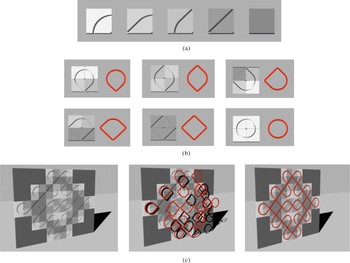
In the first project, the six motifs from the grammar were decomposed into a smaller set of three submotifs from which the original six grammar motifs, and from them, larger kolam patterns could be generated (Murphy, Reference Murphy2006). Each submotif was incised as a narrow groove on a square building tile. The submotif tiles are illustrated in Figure 9a. The complete set includes reflected versions of one submotif (the second and third tiles from the left) as well as a blank tile. To form the original motifs and larger kolam designs, tiles can be assembled by matching the endpoints of submotifs, as in the grammar. Integrated side-by-side tabs and slots were designed into each edge of each tile to allow any tile to be joined physically with any other tile along any side, subject to the endpoint matching constraint. For further structural stability, linear structural elements possibly made from locally available materials, say grasses, could be fitted in the grooves in tiles. Figure 9b shows how the submotif tiles combine to make complete motifs. The linear structural elements are indicated in dark gray (red in the online version). Figure 9c shows the building tiles assembled to make a kolam pattern. Different arrangements of tiles lead to different kolam patterns.
A kolam tile assembly system (Murphy, Reference Murphy2006). (a) Submotif tiles. Different gray tones are used here only for presentational purposes to indicate different tiles and are not intended to be part of the physical tiles. (b) Submotif tiles combine to make complete motifs. Linear structural elements are indicated in dark grey (red in the online version). (c) Tiles combine to make a wall with a kolam pattern. Linear structural elements are indicated in dark gray (red in the online version). [A color version of this figure can be viewed online at journals.cambridge.org/aie]

The building system was prototyped to test its visual and physical feasibility. Figure 10 shows the physical tiles 3-D printed at desktop scale. The prototype tiles demonstrated the ease of assembling limitless, elegant variations of kolam walls. They also demonstrated potential for a full-scale structural system. At the same time, they raised numerous questions to do with appropriate materials and sizes of the tiles, the durability of the connection features, and the function and materiality of the linear elements.
Three-dimensional printed prototype kolam tiles (Murphy, Reference Murphy2006). [A color version of this figure can be viewed online at journals.cambridge.org/aie]

In sum, the 2-D linear motifs of kolam patterns were conveyed in this project through linear detailing or relief on simple 3-D building components and then reinforced (both visually and physically) through 3-D linear elements. By contrast, in the next project, the 2-D linear motifs of kolam patterns were conveyed through the shapes of the building components defined as complex, 3-D solids (Schliecher, Reference Schliecher2006). In this project, a double-layer wall system was developed with perpendicular plug-ins connecting the two wall layers to form a rigid structure. The plug-ins were solid kolam motifs, functioning simultaneously as aesthetic and structural elements.
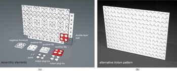
Figure 11a illustrates this system. The original six kolam motifs from the shape grammar are the basis for kolam plug-ins. The solid plug-ins are arranged in groups of four within square formworks. Positive tiles with openings are cast from the formworks. Different arrangements of motifs within a formwork produce different tiles. The tiles are then arranged, again by matching endpoints of kolam motifs, to create a wall with an overall kolam pattern. Different arrangements of tiles lead to different kolam patterns. Figure 11b shows a wall with a kolam pattern different from the one in Figure 11a and made from different tiles. A double wall is created by connecting walls back to back with plug-ins. The plug-ins are inserted into wall openings and connected with small joint elements.
A double-wall kolam tile assembly system (Schliecher, Reference Schliecher2006). (a) Assembly elements and a double wall made from them and (b) a wall with a kolam pattern different from that in (a). [A color version of this figure can be viewed online at journals.cambridge.org/aie]

The components of this assembly system were 3-D printed. Figure 12a shows the kolam plug-ins and how they fit into wall tiles to create a double wall system. Figure 12b shows a single kolam wall, with some plug-ins, demonstrating possibilities for light apertures. As with the previous project, many structural and material issues would need to be investigated to develop the main ideas.
(a) Three-dimensional printed prototype assembly components (Schliecher, Reference Schliecher2006). (b) A single kolam wall, with some plug-ins, demonstrating possibilities for light apertures (Schliecher, Reference Schliecher2006). [A color version of this figure can be viewed online at journals.cambridge.org/aie]

3.2. Litema designs
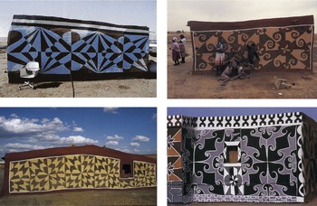
Litema are traditional, colorful designs painted by the Basotho tribe on the mud walls of their houses in the small African country of Lesotho and in the surrounding, larger country of South Africa. Figure 13 shows some examples. Like the ritual of kolam making, the design and painting of litema is a gender-specific practice: they are made only by women. Also like kolam, litema are ephemeral designs. They are washed away by seasonal rainstorms and then repainted. Litema have numerous, important cultural meanings related to fertility, cultivation, and respect for ancestors. The practice of painting houses is gradually disappearing because of changing construction practices and housing patterns. Efforts are now underway to find ways of sustaining this traditional practice. Thus, litema are very appropriate as the basis for new building systems that incorporate vernacular decoration.
Litema designs, Basotho house painting, South Africa. Photography by Gary N. van Wyk. From G. N. van Wyk, 1998, African Painted Houses. New York: Harry N. Abrams, Inc. Copyright 1998 Harry N. Abrams, Inc. Reprinted with permission.

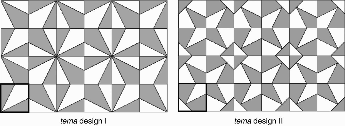
As with kolam designs, the underlying construction of a tema (singular of litema) is based on a grid of squares, or diamonds if the grid is rotated. The squares (or diamonds) may be further subdivided into half-squares or quarter-squares. A colored, abstract motif is defined and repeated within each square, half-square, or quarter-square cell of the grid. Copies of a motif within a grid often include color (figure-ground) reversals of the motif and symmetry transformations (rotations and reflections) of the motif and its color reversal. A striking feature of litema is that the underlying motif is often masked by the overall pattern and symmetries that emerge from the repetitions and transformations of the motif.
Figure 14a shows a typical grid pattern for litema. The motif is defined within a square cell. It repeats identically (technically, through translations) across all the white squares of the grid. Half-turns or 180° rotations of the motif repeat across all the dotted white squares. Combined color reversals and reflections of the motif repeat across the black squares. Half-turns of the reversed and reflected motif repeat across all of the dotted black squares. Figure 14b shows a 2 × 2 portion of the grid, with an actual motif and transformations of it in neighboring cells. The top left house in Figure 13 exemplifies this type of grid.
(a) A typical litema grid pattern and (b) a 2 × 2 portion of the grid with an actual motif and transformations of it in neighboring cells.

A shape grammar that generates this grid pattern is straightforward and can be defined in different ways. Figure 15a shows one possible grammar, and Figure 15b shows a computation of a grid using the rules. The rules create grids starting with the bottom leftmost cell together with a motif defined for that cell. Grid cells with this motif and transformations of it are then added one at a time to create the bottom row, then the second row, and so on, until the top row is defined. Any number of rows and columns are possible. Labels for controlling applications of these rules to generate only rectangular grids are not shown in the grammar here for the sake of simplicity. Labels are straightforward to add and could be defined, for example, like those in the Chinese lattice grammar, which generates similar kinds of grids (see Stiny, Reference Stiny1977, pp. 90–91).
(a) A shape grammar for the litema grid in Figure 14a and (b) a computation of a grid using the rules in (a).

The litema shape grammar was the basis for an assembly system for dome structures, rather than simple wall sections (Cira, Reference Cira2007). In this project, the litema grid cells of the grammar were interpreted as flat, trapezoidal building components. The colored litema motifs were rerepresented as relief shapes on components. Concrete was the proposed building material. A digital, parametric model was developed for generating precise digital representations of all of the individual components for any height and diameter of a dome, given any motif. The sizes and shapes of the components varied according to their positions in the dome. Angled tabs and slots were integrated into components for secure connections between components to create a rigid, free-standing structure. Side tabs and slots were full length so that components could easily slide into place.
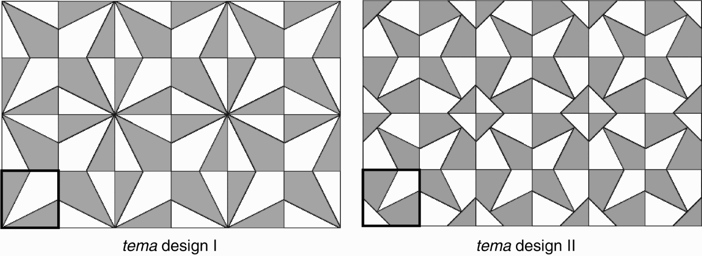
Figure 16 shows two litema, each made from a different, invented motif. The components for a dome based on each tema design were generated using the digital model and then 3-D printed. Figure 17a shows the assembly of one of the litema domes in progress. Figure 17b shows the two domes fully assembled.
Two new litema designs with motifs highlighted (Cira, Reference Cira2007).
(a) Assembling a tema dome (Cira, Reference Cira2007) and (b) Tema I and Tema II domes (Cira, Reference Cira2007). [A color version of this figure can be viewed online at journals.cambridge.org/aie]

The assembly system developed for this project was very much like the first kolam assembly system described in Section 3.1. Both systems were based on grids, with grid components or tiles that fit together with integrated, hidden tab and slot features. In both systems, the visual motifs were expressed through detailing or relief on building components. In the kolam system, different patterns are generated by rearranging the tiles so that different motifs combine in different ways. In the litema system, however, different patterns are created by keeping the tile arrangement the same and substituting a different motif on all tiles. Different motifs are easily substituted in the digital model of the assembly system to fabricate tiles for different dome patterns. As with the kolam projects, however, many additional structural and material factors would need to be considered for a full-scale assembly system.
3.3. Meander designs
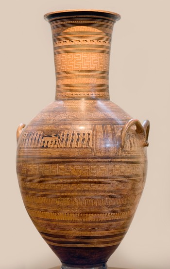
Meander designs are found in many cultures, places, and times, and used as decorative elements on artifacts from jewelry to buildings. An especially elaborate and visually sophisticated form of the meander emerged in ancient Greece during the Late Geometric period (8th century BC) on painted pottery and other objects. A vase painted by one of the earliest and most influential Late Geometric painters, the so-called Dipylon Master, is shown in Figure 18. Several different meander forms circle around the pot in horizontal bands. An in-depth analysis of Geometric meander designs using shape grammars is given in Knight (Reference Knight1986) and summarized here. Readers should refer to the 1986 paper for details omitted in the following illustrations and discussion of the grammars.
A late geometric amphora depicting a funeral ritual. From the Dipylon cemetery, Athens (ca. 750 BCE). National Archaeological Museum, Athens, Greece. Photo courtesy of Vanni/Art Resource, New York. Reprinted with permission. [A color version of this figure can be viewed online at journals.cambridge.org/aie]

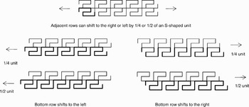
One of the simpler meander forms is the single or running meander. It can “run” to the right or to the left as illustrated in Figure 19. The more intricate, multistory meanders typical of the Late Geometric period are created from running meanders in a subtle but systematic way. Multistory meanders are created by stacking running meanders one on top of another. Many variations of multistory meanders are possible, and are the result of changing the directionalities of rows (running to the right or to the left), and by changing the vertical alignments of rows. Rows can be aligned, or one row can be shifted in relation to the row above or below by one-quarter or one-half of a basic S-shaped unit. Figure 20 shows how a row can be shifted in relation to an adjacent row.
The running meander that can run to the (top) right or (bottom) left.

Adjacent meander rows can be shifted in relation to one another.

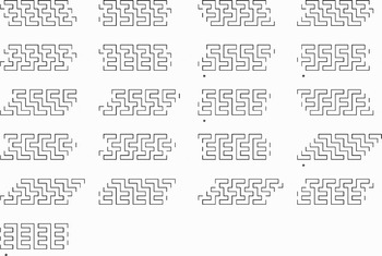
A shape grammar that generates multistory meanders is shown in Figure 21a. The first rule applies recursively to generate the length of a multistory meander, starting with a line segment representing the basic S-motif of a meander. Labels are used to mark the extent of each line segment. The second rule is a “stacking” rule. It applies recursively to generate the height of a multistory meander by creating any number of labeled lines parallel to the labeled line generated by the first rule. This particular stacking rule generates rows shifted by one-quarter unit and running in different directions. Similar stacking rules for different shifts and directionalities of rows can be defined. The third rule of the grammar replaces labeled line segments with S-shapes. The computation in Figure 21b shows how a double-height meander is constructed. To create a final design (the single, continuous line meander shown at the bottom), an additional erasing rule is necessary but not shown here. The erasing rule deletes all lines at the top of one row that do not overlap lines at the bottom of the adjoining row. Some of the many multistory meanders that can be generated by grammars with stacking rules are shown in Figure 22.
(a) A shape grammar for multistory Greek meanders and (b) a computation of a multistory meander using the grammar.

Multistory meanders. Asterisks indicate extant designs. All others are new, hypothetical designs or at least ones not known to the author of the grammar.

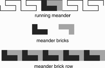
The meander language and shape grammar were the basis for a double-wall assembly system (Goldenberg, Reference Goldenberg2007). In this project, the 2-D, linear S-motif of meander designs was expressed though the shape and color of 3-D “meander bricks.” The translation of the linear meander motifs into 3-D building components was a two-step process. In the first step, the linear designs were translated into 2-D, planar “meander bricks” to test possibilities for a wall system in elevation. Figure 23 shows the decomposition of a running meander into two differently colored L-shaped meander bricks. The meander bricks combine to form a row of bricks.
Translation of the linear running meander into two-dimensional meander bricks that combine to form a brick row.

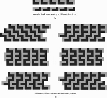
Two, directional variations of meander brick rows, analogous to left and right running meanders, were defined next. Figure 24a shows the two different variations. Rows were then stacked one on top of each other and shifted by different amounts, in the manner of the original multistory meanders, to create brick wall elevations. Figure 24b illustrates some of the many different elevation patterns that can be generated through different combinations of left running and right running brick rows.
(a) Right-running and left-running brick rows are stacked to form (b) different elevation patterns.

With this promising preliminary study in hand, the 2-D meander bricks were then translated into 3-D building components of a double-wall system. The components were artfully designed to function both visually and structurally: their shapes reproduce the meander motif and also facilitate interlocking. Figure 25 shows the two basic components, or meander bricks, 3-D printed. Each component is a different color. Each component has two parallel L-shaped faces that replicate the elevation elements from the 2-D study above, and combine to make meander patterns on both the outside and inside elevations of a wall. Each component includes a gap that creates an air pocket in between a double wall. One component includes integrated aligners to facilitate the interlocking of components, both horizontally and vertically, without the use of mortar. Otherwise, the two components are identical.
The two interlocking three-dimensional meander brick components (Goldenberg, Reference Goldenberg2007). [A color version of this figure can be viewed online at journals.cambridge.org/aie]

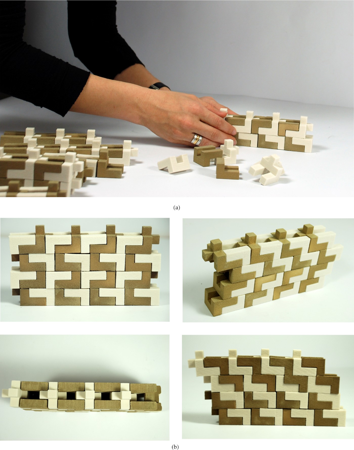
The two components interlock together as shown. Multiples of these then fit together to make a row. The horizontal aligners keep the components from moving laterally. Rows of different directionalities are produced by simply reversing the direction of the components. Rows are stacked to make a double wall. The vertical aligners act as stops or spacers so that stacked rows can be aligned, shifted one-quarter unit, or shifted one-half unit as in the original grammar. Both the vertical and horizontal aligners on meander components function in effect as physical equivalents to labels in a shape grammar. They guide and control how components can be assembled horizontally into rows and how rows can be assembled vertically into walls. Figure 26a shows a wall being assembled. Figure 26b shows some of the many different meander patterns that can be made by stacking and shifting rows in different ways.
(a) A meander wall being assembled (Goldenberg, Reference Goldenberg2007) and (b) different wall patterns created by stacking and shifting brick rows in different ways (Goldenberg, Reference Goldenberg2007). [A color version of this figure can be viewed online at journals.cambridge.org/aie]
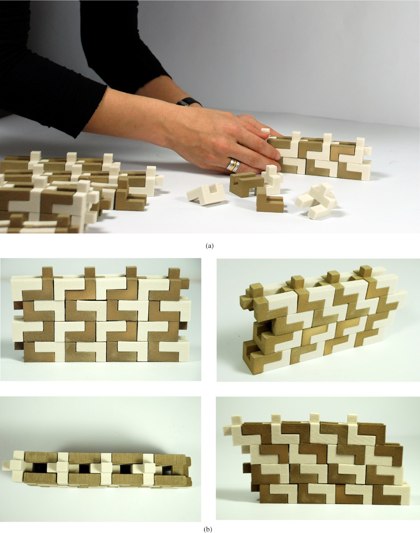
This pilot study is now being developed further under the auspices of a National Science Foundation (Award Number 0748992). This latest work will provide a rigorous proof-of-concept demonstration that a visual, decorative design language can be incorporated into a building system for structurally sound assemblies with visual variations. The specific aim is to develop an automated grammar that specifies the full-scale visual, physical, and material details of assembly components for a representative section of a 3-D enclosure: a corner wall section. That is, the grammar will have rules to generate complete CAD/CAM data for fabrication of corner wall assemblies with meander pattern variations. A full-scale mockup of a corner wall section will be built.
4. DISCUSSION AND FUTURE DIRECTIONS
The pilot studies described here point to the rich potential of combining shape grammars and digital fabrication to advance jointly the visual and physical aspects of mass customizable building assembly design. Shape grammars provide the means to understand and generate complex and meaningful visual designs and have a long history of successful and compelling applications in the analysis of visual languages. Digital fabrication technologies and related, developing theories provide the means for economic, fast, and high-quality production of complex and variable building components and systems. In recent years, architects and designers have begun to take advantage of the capabilities of new digital technologies to reintroduce ornament and decorative design into built form. However, much of this work focuses on surface ornament, that is, ornamental effects or texturing on the surface or skin of a building. The works of Herzog and de Meuron provide beautiful examples of this approach. When ornament is more integrated with structure, it is often treated (or at least portrayed) as a consequence of structural or other performance considerations. The elegant, spiraling diagrid of Norman Foster's Swiss Re tower, shaped in large part by structural and environmental factors, exemplifies this approach. Moreover, ornament in contemporary digital architecture projects tends to be ahistorical and acultural, and rarely achieves, or aims for, the visual depth, geometric complexity, and expressiveness of vernacular decorative traditions, which have been developed and practiced over hundreds of years.
By contrast, the projects here aim for the visual sophistication and cultural specificity of vernacular design. They also seek to blur the boundaries between structural elements and decorative elements, and to question causal relationships between the two. Indeed, the pilot studies suggest that visual qualities can drive physical ones. In other words, looking at structure in terms of visual design, and visual design in terms of shape grammars, can inspire ideas for structures and assemblies. For example, in the second kolam study and in the meander study, the visual grammar elements actually suggested novel designs for components and connecting features.
Much of the appeal of these two systems, as well as the others, derives from their unique structural and visual qualities. An important next step is to investigate how and whether strategies for merging decorative design and structure in building systems can be generalized for a range of visual languages across different cultural, geographic, and environmental contexts. The time, expense, and general logistics of developing entirely new systems for different places, particularly in emergency situations, would negate the rationale for these systems.
A first step in a general approach for translating any visual, vernacular language into a building system would be the identification of a shape grammar for the language. Vernacular or other visual pattern languages can often be characterized as languages of 2-D, infinite “wall-paper” patterns. Grammars for such patterns can be developed by parsing the patterns into repeating visual elements or motifs and defining shape rules for recombining motifs to generate pattern variations. The motifs and rules of combination would then need to be translated into the interlocking building components of an assembly system, as was done in the pilot studies described here. The pilot studies suggest a spectrum of strategies for this important step.
At one end of the spectrum, motifs might be expressed through detailing on simple, polygonal (in elevation) components that interlock in a regular grid or lattice with hidden slot and tab features. The first kolam project and the litema project made use of this strategy. At the other end of the spectrum, motifs can be expressed through components with uniquely defined shapes, which also facilitate interlocking. The second kolam project and the meander project used this strategy. Color or other material properties of components can also be used to convey motifs, as in the meander project. Strategies that combine ideas from the two ends of the spectrum are also possible. None of these strategies are necessarily straightforward, however. The relationships between patterns (designs made up of a repeating motif against a background) and tilings or tessellations (designs made up of space-filling shapes similar to the assembly systems considered here) can be complex and nontrivial. An interesting mathematical start on this problem is provided by Jablan (Reference Jablan2002), who shows how some common vernacular patterns can be reproduced with simple modular tilings. Grünbaum and Shepard (Reference Grünbaum and Shephard1987) give a systematic and comprehensive overview of patterns and tilings and the relationships between the two.
As already suggested, more work is also needed to test the structural, material, and aesthetic viabilities of the prototype systems for complete houses and other structures at full-scale. The corner wall mockup of the meander system is a first step in that direction. For complete houses, visual aspects would matter as much as physical ones. For example, the scale, placement, and extent of visual patterning across a building structure would be important. Certainly any of the prototype systems could be modified easily for patterning only on specific parts of a building by integrating or not integrating motifs or colors within building components.
More generally, the systems proposed here hold strong promise for the fast construction of mass-customized, expressive structures. The physical production methods for carrying out these systems in the real world can be low cost and allow for the rapid design and manufacture of many products from furniture to houses. A single CNC machine can rapidly produce many houses from CAD files in much the same way that paper printers can be used to produce books from digital files. A major advantage of these methods is that they remove many repetitive steps in measuring, cutting, and assembly found in traditional design and construction, thus lowering costs.
New CAD/CAM techniques for the easy production of building components cast from CNC-cut layered molds are currently under development (Griffith & Kamath, Reference Griffith and Kamath2009). These techniques are aimed at making possible mortarless concrete or aggregate interlocking block assembly systems such as the one proposed in the meander project. With these techniques, an unskilled individual or small group could produce a core number of blocks each day and build sections of a structure based on the number of blocks produced daily. A small house might be built this way in less than 3 weeks. Further, these new techniques allow for the manufacture of uniquely shaped and customized components needed for the expression of diverse, culturally responsive, visual patterns on houses. By contrast, current commercially available mortarless, interlocking block systems are limited to just a few standard block types. [For examples of commercial systems, see the Haener Block (http://www.haenerblock.com/), Sparlock (http://www.sparlock.com/), Habitech International (http://www.habitech-international.com/blank.html), and Azar systems (http://www.azarblock.com/)]. Despite their advantages, however, the building systems described here have limitations that are similar to those found in Contour Crafting (see pp. 7–8). Further development is needed for the assembly of overhanging elements and common angular roof types in addition to simple walls.
To realize this vision of low-cost, high-quality assembly manufacture in rural or developing areas, access to CAD design tools, CNC machinery, and sustainable materials is key. Research on these issues is also underway (K. Griffith, unpublished data). Proposals include implementing building assembly systems as Web-based software (grammar) applications, allowing potential users to access and use the systems from any location using wireless, Internet-connected devices with simple graphics interfaces. The main processes of the systems could be calculated and computed using distributed server technology. CNC machines for fabricating building components could be placed strategically in central locations within major cities and towns where molds can be manufactured and then purchased, loaned, or leased by individuals or groups. Beyond these important practical issues, there are equally important cultural and social issues regarding the validity and acceptability of this new way of building for particular communities or cultures. All of these issues need ultimately to be addressed through full-scale, real-world studies in tandem with the more experimental work now being done.
Terry Knight is a Professor of design and computation in the School of Architecture and Planning at the Massachusetts Institute of Technology. Her research and teaching focuses on the use of shape grammars and other generative systems and supporting digital technologies for design synthesis and design exploration. Her book, Transformations in Design, is a well-known introduction to the field of shape grammars.
Lawrence Sass is an Associate Professor in the School of Architecture and Planning at the Massachusetts Institute of Technology, where he teaches courses in digital fabrication and design computing. Sass has developed theoretical methods to build houses of wood and concrete manufactured by computer-controlled machinery. His work is a demonstration of a new model of community-based home design and delivery with computers and digital fabrication devices.