1. Introduction
The cable-driven continuum robots (CDCRs) are inspired by biological structures such as snake-like robots [Reference Guo, Sun and Sun1], bionic elephant trunk robots [Reference Huang, Wang, Wang, Xia and Li2], and soft arm of octopus [Reference Xie, Yuan, Liu, Tian, Chen, Fu, Mao, Jin, Wang, He, Wang, Mo, Ding, Zhang, Laschi and Wen3]. Compared with rigid manipulators, CDCRs utilize continuous bending structures instead of the traditional bone and joint structures, allowing for the super capability of flexibility, lightweight, and scalability. CDCRs have been widely applied in minimally invasive surgery [Reference Dupont, Simaan, Choset and Rucker4], exploration [Reference Wei, Ju, Guo, Chen and Wu5], anti-terrorism rescue [Reference Wang, Xing, Xu and Hu6], and so on. Additionally, CDCRs need less driven motors than rigid manipulators, making them highly effective for underwater applications. However, due to their innate soft structures and infinite degrees of freedom, it is challenging to develop an accurate and robust trajectory tracking algorithm to complete the trajectory tracking of CDCRs in underwater application scenarios.
In recent years, scholars have carried out a series of studies on the impact of uncertainties (joint friction, parameter perturbation, and high-order unmodeled dynamics) on the trajectory tracking performance of quadrotors [Reference Khadhraoui, Zouaoui and Saad7] and manipulators [Reference Gao, Ma, Zhang and Zhou8]. These studies mainly include proportional integral derivative [Reference Ghoul, Kara, Benrabah and Nasri9], fuzzy control [Reference Cao, Zhao, Ye, Yu, Li and Jiang10], backstepping [Reference Xu, Guo, Li, Huo, Sun, Zhang, Xing, Liu, Ma and Ding11], and sliding mode control (SMC) [Reference Ghoul, Kara, Benrabah and Hadjili12]. SMC being a robust, fast-response, and simple-structure nonlinear control method has been widely utilized in various industries and applications to achieve robust and accurate trajectory tracking control [Reference Sun, Yu, Zheng, Tao, Sun, Sun, Dehmer and Chen13–Reference Ding, Ding, Wei and Mei15]. However, it is difficult for the conventional SMC to meet the requirements of accuracy, stability, and robustness for underwater application scenarios of CDCRs. To suppress the chattering in SMC, Yu et al. [Reference Yu, Yu, Shirinzadeh and Man16] developed a terminal sliding mode control (TSMC) for the motion control of CDCRs. A nonlinear term is applied to the TSMC to ensure finite-time convergence. However, the negative power term of the sliding manifold in the TSMC can easily lead to singularity, making the control signal unbounded. To solve the singularity problem in the TSMC, Cruz-Ortiz et al. [Reference Cruz-Ortiz, Chairez and Poznyak17] presented a practical nonsingular terminal sliding mode control (NTSMC). However, the slow convergence rate of the NTSMC makes it difficult to satisfy the requirement of the CDCR in complex application scenarios. To overcome the drawback of the NTSMC, a novel fast nonsingular terminal sliding mode control (FNTSMC) [Reference Mobayen, El-Sousy, Alattas, Mofid, Fekih and Rojsiraphisal18] was proposed to improve the convergence speed. However, the FNTSMC cannot make the tracking error converge to zero in finite time under disturbances. Yang et al. [Reference Yang, Deng, Li, Sun, Cao and Wei19] proposed an integral terminal sliding mode control to ensure that the tracking error reaches zero within a limited time. However, the limitation of this control strategy lies in the challenge of accurately measuring the system uncertainties.
Due to the unpredictability and rapid variability of underwater application scenarios, it is challenging for CDCRs to perform underwater tasks. Therefore, improving the anti-interference ability of CDCRs in complex and unknown application scenarios is crucial [Reference Dian, Zhu, Xiang, Ma, Liu and Guo20]. Many scholars have designed various anti-interference observers to improve the robustness of control system. Zhu et al. [Reference Zhu, Tu, Jiang, Pan, Huang and Tu21] presented a Luenberger sliding mode observer, in which the observed value is fed back to the sliding mode controller to reduce the influence of external disturbances. However, this estimation method leads to significant deviations in the estimation result due to the cumulative error. Hou et al. [Reference Hou and Ding22] conducted a finite-time extended state observer, which introduces a nonlinear error compensation correction term to eliminate the cumulative error. Nevertheless, this method has a significant computational burden. The great advantages of high approximate accuracy, adaptive parameter adjustment, and online training to eliminate the cumulative error make adaptive neural network (ANN) widely used in nonlinear and uncertain systems, such as flexible manipulator systems [Reference Li, Ma, Meng, Zhang and Yin23], MIMO systems [Reference Liu, Zhao, Liu, Li, Tong and Chen24], and helicopter systems [Reference Zhao, Zhang, Liu, Mu and Hong25]. Feng et al. [Reference Feng, Song, Ma, Ma, Yin, Cao and Yu26] proposed the RBFNN for an electro-hydraulic servo to approximate the uncertainties. Nevertheless, this method utilizes two adaptive laws to estimate uncertainties, which undoubtedly increases the computational complexity and slows down the response speed.
Motivated by the above research, an ANN-based fast nonsingular integral terminal sliding mode controller (ANN-FNITSMC) is developed to enhance the trajectory tracking performance of CDCRs in the underwater environment. The fast nonsingular integral terminal sliding mode controller (FNITSMC) is used to solve the chattering and singularity problems of the traditional TSMC. An ANN is constructed to estimate uncertainties and compensate for the control input, thereby improving the accuracy, stability, and robustness of the trajectory tracking control. The main contributions of this paper are as follows:
1) The proposed FNITSMC replaces the fractional power terms with the integral power terms to avoid the singularity problem, thereby enhancing tracking accuracy and stability in the complex underwater environment. Additionally, the
 $\text{sigmoid}(x)$
function is substituted for the
 $\mathrm{sgn}(x)$
function in the traditional SMC to mitigate the chattering.
2) The ANN-based estimator requires only a single adaptive parameter to obtain the lumped uncertainty that includes the current disturbance, fluid viscosity, and uncertain dynamics in complex underwater application scenarios. The tracking accuracy and robustness are improved by using the estimated lumped uncertainty to compensate for the control input.
3) The effectiveness of the proposed algorithm has been validated through simulations and experiments. The results show that ANN-FNITSMC exhibits superior trajectory tracking performance of strong robustness and high-stable accuracy under challenging conditions such as water flow and fluid viscosity.
The remainder of this article is organized as follows. In Section 2, the dynamic and nonlinear model of the system is established. The design of ANN-FNITSMC is discussed in Section 3, where the Lyapunov function is used to prove the stability and finite-time convergence of the proposed algorithm. In Section 4, the stability, robustness, and accuracy of ANN-FNITSMC are verified by both simulations and experiments.
2. Dynamic model of CDCRs
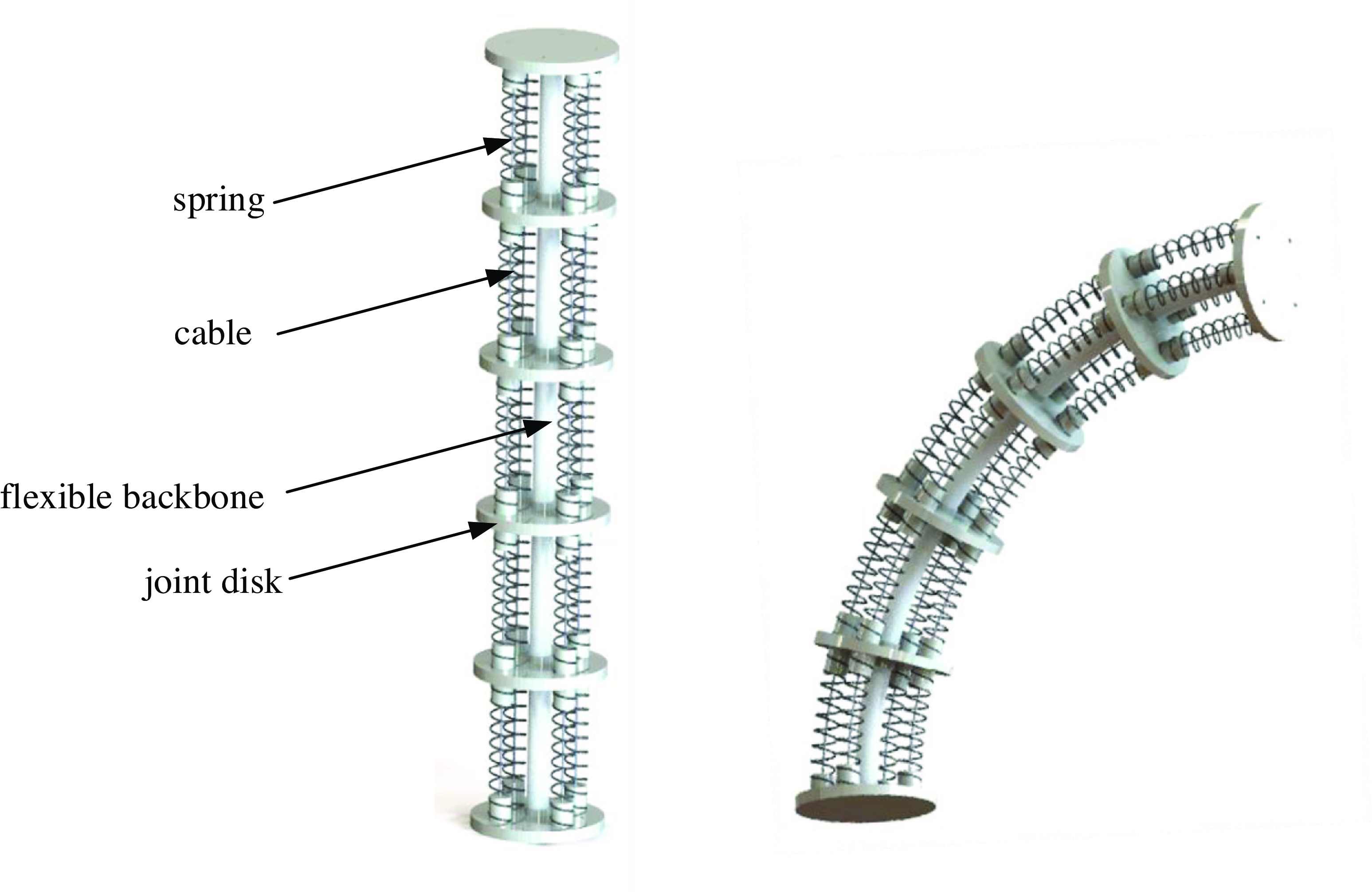
The designed CDCR consists of a flexible backbone, 6 joint disks, 4 cables, and several springs, as shown in Figure 1. The cables are connected to the driving motors to transmit torque signals, which control the robot to track the desired trajectory. The springs between the joint disks mainly provide support.
The structure of the CDCR.

The dynamic model of the CDCR can be described by Lagrange method [Reference Yang, Peng, Zhou, Zhang and Wu27–Reference Zhang, Liu, Huo, Wu, Yang and Yu28] as:
 \begin{equation} \boldsymbol{I}(\boldsymbol{a})\ddot{\boldsymbol{a}}+\boldsymbol{K}(\boldsymbol{a},\dot{\boldsymbol{a}})\dot{\boldsymbol{a}}+\boldsymbol{G}(\boldsymbol{a})=\boldsymbol{T}_{0} \end{equation}
where
 $\boldsymbol{a}, \dot{\boldsymbol{a}}$
, and
 $\ddot{\boldsymbol{a}}$
represent the position, velocity, and acceleration vectors of the tip, respectively.
 $\boldsymbol{I}(\boldsymbol{a})$
represents the inertia matrix of the CDCR,
 $\boldsymbol{K}(\boldsymbol{a},\dot{\boldsymbol{a}})$
refers to the Coriolis force and centrifugal force matrix,
 $\boldsymbol{G}(\boldsymbol{a})$
denotes the gravity term, and
 $\boldsymbol{T}_{0}$
is the torque exerted on the joints.
However, CDCRs are easy to be disturbed due to their flexible structures. Therefore, to improve the tracking accuracy of CDCRs, it is necessary to consider the frictional forces and unknown interferences in the working environment. By introducing these interference items and representing them with
 $\boldsymbol{T}_{\mathrm{d}}$
, Eq. (1) can be rewritten as:
 \begin{equation} \boldsymbol{I}(\boldsymbol{a})\ddot{\boldsymbol{a}}+\boldsymbol{K}(\boldsymbol{a},\dot{\boldsymbol{a}})\dot{\boldsymbol{a}}+\boldsymbol{G}(\boldsymbol{a})+\boldsymbol{T}_{\mathrm{d}}=\boldsymbol{T}_{0} \end{equation}
It is challenging to derive the accurate calculations of
 $\boldsymbol{I}(\boldsymbol{a}), \boldsymbol{K}(\boldsymbol{a},\dot{\boldsymbol{a}})$
, and
 $\boldsymbol{G}(\boldsymbol{a})$
, which are assumed to satisfy the following conditions [Reference Qin, Chen and Ming29]:
 \begin{equation} \left\{\begin{array}{l} \boldsymbol{I}(\boldsymbol{a})=\hat{\boldsymbol{I}}(\boldsymbol{a})+\Delta \boldsymbol{I}(\boldsymbol{a})\\ \boldsymbol{K}(\boldsymbol{a},\dot{\boldsymbol{a}})=\hat{\boldsymbol{K}}(\boldsymbol{a},\dot{\boldsymbol{a}})+\Delta \boldsymbol{K}(\boldsymbol{a},\dot{\boldsymbol{a}})\\ \boldsymbol{G}(\boldsymbol{a})=\hat{\boldsymbol{G}}(\boldsymbol{a})+\Delta \boldsymbol{G}(\boldsymbol{a}) \end{array}\right. \end{equation}
where
 $\hat{\boldsymbol{I}}(\boldsymbol{a}), \hat{\boldsymbol{K}}(\boldsymbol{a},\dot{\boldsymbol{a}})$
and
 $\hat{\boldsymbol{G}}(\boldsymbol{a})$
are the estimates of
 $\boldsymbol{I}(\boldsymbol{a}), \boldsymbol{K}(\boldsymbol{a},\dot{\boldsymbol{a}})$
, and
 $\boldsymbol{G}(\boldsymbol{a})$
, respectively.
 $\Delta \boldsymbol{I}(\boldsymbol{a}), \Delta \boldsymbol{K}(\boldsymbol{a},\dot{\boldsymbol{a}})$
and
 $\Delta \boldsymbol{G}(\boldsymbol{a})$
are the system uncertainties. Substituting Eq. (3) into Eq. (2), the following equation can be obtained:
 \begin{equation} \hat{\boldsymbol{I}}(\boldsymbol{a})\ddot{\boldsymbol{a}}+\hat{\boldsymbol{K}}(\boldsymbol{a},\dot{\boldsymbol{a}})\dot{\boldsymbol{a}}+\hat{\boldsymbol{G}}(\boldsymbol{a})+\boldsymbol{F}\left(\boldsymbol{a},\dot{\boldsymbol{a}},\ddot{\boldsymbol{a}}\right)=\boldsymbol{T}_{0} \end{equation}
where
 $\boldsymbol{F}(\boldsymbol{a},\dot{\boldsymbol{a}},\ddot{\boldsymbol{a}})=\boldsymbol{T}_{\mathrm{d}}+\Delta \boldsymbol{I}(\boldsymbol{a})+\Delta \boldsymbol{K}(\boldsymbol{a},\dot{\boldsymbol{a}})+\Delta \boldsymbol{G}(\boldsymbol{a})$
is the uncertain term of the system.
In addition, the dynamic model of the CDCR has the following basic properties [Reference Amouri, Mahfoudi and Zaatri30]:
1) The inertia matrix
 $\boldsymbol{I}(\boldsymbol{a})$
being of positive definite symmetric and bounded satisfies the following inequalities:
 \begin{equation} \mathbf{0}\lt \lambda _{\min }\left\{\boldsymbol{I}(\boldsymbol{a})\right\}\leq \left\| \boldsymbol{I}(\boldsymbol{a})\right\| \leq \lambda _{\max }\left\{\boldsymbol{I}(\boldsymbol{a})\right\} \end{equation}
where
 $\lambda _{\min }\{\cdot \}$
and
 $\lambda _{\max }\{\cdot \}$
are the minimum and maximum eigenvalues of the matrix, respectively,
 $\| \cdot \|$
is the 2-norm of the matrix.
2) The Coriolis force and centrifugal force matrix
 $\boldsymbol{K}(\boldsymbol{a},\dot{\boldsymbol{a}})$
satisfies the following relationship:
 \begin{equation} \boldsymbol{K}\left(\boldsymbol{a},x\right)y=\boldsymbol{K}\left(\boldsymbol{a},y\right)x\,\forall \boldsymbol{a} x,y\in \mathbf{R} \end{equation}
 \begin{equation} 0\lt \chi _{1}\left\| \dot{\boldsymbol{a}}^{2}\right\| \leq \left\| \boldsymbol{K}(\boldsymbol{a},\dot{\boldsymbol{a}})\dot{\boldsymbol{a}}\right\| \leq \chi _{2}\left\| \dot{\boldsymbol{a}}^{2}\right\| \forall \boldsymbol{a},\dot{\boldsymbol{a}}\in \mathbf{R}^{n} \end{equation}
where
 $\chi _{1}$
and
 $\chi _{2}$
are positive constants.
3)
 $\dot{\boldsymbol{I}}(\boldsymbol{a})-2\boldsymbol{K}(\boldsymbol{a},\dot{\boldsymbol{a}})$
is a skew-symmetric matrix that satisfies the following function:
 \begin{equation} \boldsymbol{\upsilon }^{\boldsymbol{T}}\left[\dot{\boldsymbol{I}}(\boldsymbol{a})-2\boldsymbol{K}(\boldsymbol{a},\dot{\boldsymbol{a}})\right]\boldsymbol{\upsilon }=\mathbf{0},\,\forall \boldsymbol{\upsilon }\in \mathbf{R}^{n} \end{equation}
3. ANN-FNITSMC controller design
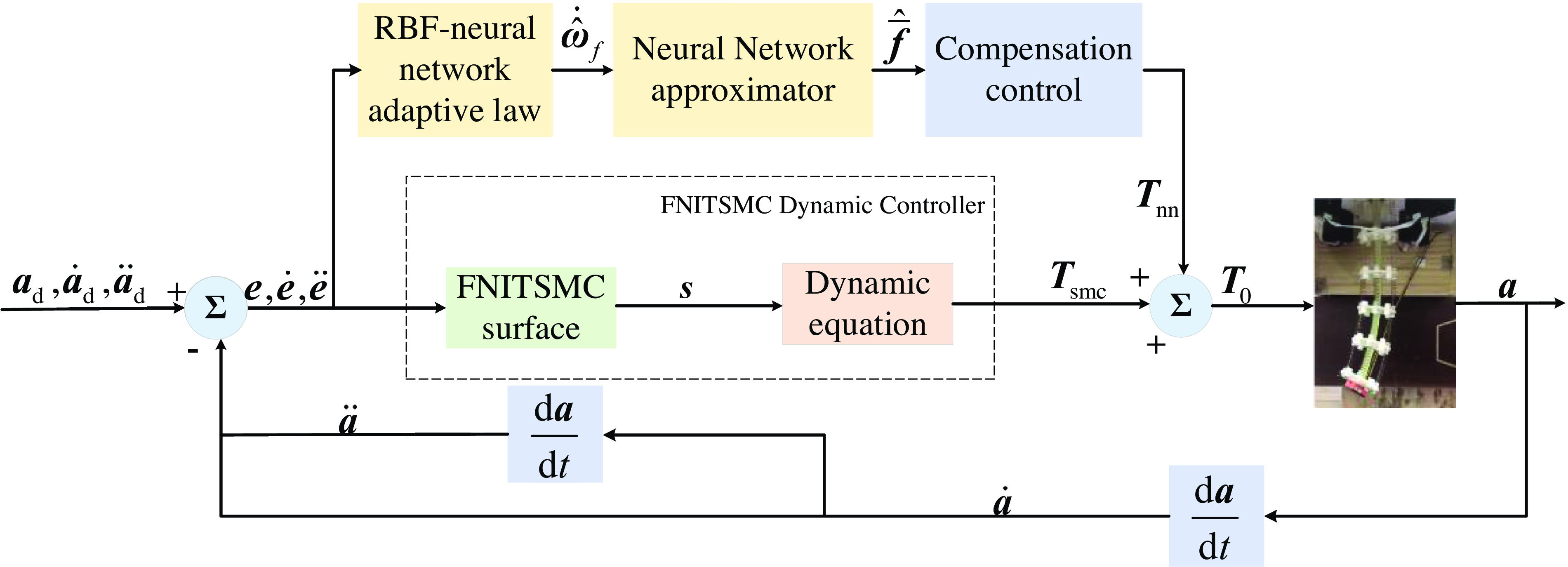
In this section, an ANN-FNITSMC controller composed of a FNITSMC and an ANN is designed to enhance the trajectory tracking performance of the CDCR in the underwater environment. FNITSMC controls the CDCR to track the reference trajectory based on the dynamic function of the CDCR. And ANN is employed to derive the estimation of the lumped uncertainty, which can be used to compensate for the control input. The control diagram of ANN-FNITSMC is shown in Figure 2. FNITSMC solves the singularity problem and ensures finite-time convergence by introducing the power integral terms and the exponential approach law. Meanwhile, the
 $\mathrm{sgn}(x)$
function is replaced with the
 $\text{sigmoid}(x)$
function to mitigate the chattering. Besides, ANN estimates the uncertainties by adjusting the adaptive weights. The accuracy, stability, and robustness of the trajectory tracking control are significantly improved with the implementation of ANN-FNITSMC.
Control diagram of the designed scheme.

3.1. FNITSMC design
In this subsection, a FNITSMC function is designed to realize rapid transient response without the chattering and singularity.
Define the tracking error as follows:
 \begin{equation} \left\{\begin{array}{l} \boldsymbol{e}=\boldsymbol{a}_{\mathrm{d}}-\boldsymbol{a}\\ \dot{\boldsymbol{e}}=\dot{\boldsymbol{a}}_{\mathrm{d}}-\dot{\boldsymbol{a}}\\ \ddot{\boldsymbol{e}}=\ddot{\boldsymbol{a}}_{\mathrm{d}}-\ddot{\boldsymbol{a}} \end{array}\right. \end{equation}
where
 $\boldsymbol{a}_{\mathrm{d}}, \dot{\boldsymbol{a}}_{\mathrm{d}}$
, and
 $\ddot{\boldsymbol{a}}_{\mathrm{d}}$
are the preset values of the position, velocity, and acceleration vectors of the tip, respectively.
A common surface of TSMC is designed as follows:
 \begin{equation} \boldsymbol{s}=\dot{\boldsymbol{e}}+\beta _{1}\,\mathrm{sgn}(\boldsymbol{e})^{m/n}+\beta _{2}\,\mathrm{sgn}(\dot{\boldsymbol{e}})^{p/q} \end{equation}
where
 $\beta _{1}, \beta _{2}\gt 0$
, p, q are the positive odd integers that satisfy 1<p/q<2, and m, n are the odd integers that satisfy m/n>p/q.
The fractional power terms
 $\beta _{1}\,\mathrm{sgn}(\boldsymbol{e})^{m/n}$
and
 $\beta _{2}\,\mathrm{sgn}(\dot{\boldsymbol{e}})^{p/q}$
may cause singularities when
 $\boldsymbol{e}=0$
and
 $\dot{\boldsymbol{e}}\neq 0$
. To solve this problem, a power integral term
 $\int _{0}^{t}[\boldsymbol{\varphi }_{1}\lambda _{1}(\boldsymbol{e},\gamma _{1},\rho _{1},\varepsilon _{1})+\boldsymbol{\varphi }_{2}\lambda _{2}(\dot{\boldsymbol{e}},\gamma _{2},\rho _{2},\varepsilon _{2})]\mathrm{d}t$
is used to substitute the fractional power terms. Therefore, the sliding surface
 $\boldsymbol{s}$
can be rewritten as:
 \begin{equation} \boldsymbol{s}=\dot{\boldsymbol{e}}+\int _{0}^{t}\left[\boldsymbol{\varphi }_{1}\lambda _{1}(\boldsymbol{e},\gamma _{1},\rho _{1},\varepsilon _{1})+\boldsymbol{\varphi }_{2}\lambda _{2}(\dot{\boldsymbol{e}},\gamma _{2},\rho _{2},\varepsilon _{2})\right]\mathrm{d}t \end{equation}
where
 $\gamma _{i}, \varepsilon _{i}$
and
 $\rho _{i} (i=1,2)$
are all constants and satisfy
 $0\lt \gamma _{2}\lt 1,\gamma _{1}=\gamma _{2}/(2-\gamma _{2}), \rho _{i}\geq 1$
, and
 $\varepsilon _{i}\gt 0$
.
 $\boldsymbol{\varphi }_{1}=\text{diag}(\boldsymbol{\varphi }_{11},\boldsymbol{\varphi }_{12},\ldots, \boldsymbol{\varphi }_{1n})$
and
 $\boldsymbol{\varphi }_{2}=\text{diag}(\boldsymbol{\varphi }_{21},\boldsymbol{\varphi }_{22},\ldots, \boldsymbol{\varphi }_{2n})$
are positive definite matrices. Therefore, the power integral term can avoid singularities.
 $\lambda _{i}(\boldsymbol{e}_{i},\gamma _{i},\rho _{i},\varepsilon _{i})$
satisfies:
 \begin{equation} \lambda _{1}(\boldsymbol{e},\gamma _{1},\rho _{1},\varepsilon _{1})=\left\{\begin{array}{c} \mathrm{sig}(\boldsymbol{e})^{{\gamma _{1}}},\left| \boldsymbol{e}\right| \leq \varepsilon _{1}\\ \varepsilon _{1}^{\gamma _{1}-\rho _{1}}\mathrm{sig}(\boldsymbol{e})^{{\gamma _{1}}},\left| \boldsymbol{e}\right| \gt \varepsilon _{1} \end{array}\right. \end{equation}
 \begin{equation} \lambda _{2}(\dot{\boldsymbol{e}},\gamma _{2},\rho _{2},\varepsilon _{2})=\left\{\begin{array}{c} \mathrm{sig}(\dot{\boldsymbol{e}})^{{\gamma _{2}}},\left| \dot{\boldsymbol{e}}\right| \leq \varepsilon _{2}\\ \varepsilon _{2}^{\gamma _{2}-\rho _{2}}\mathrm{sig}(\dot{\boldsymbol{e}})^{{\gamma _{2}}},\left| \dot{\boldsymbol{e}}\right| \gt \varepsilon _{2} \end{array}\right. \end{equation}
Additionally, the
 $\mathrm{sgn}(x)$
function in the fractional power terms has an infinite switching frequency, which makes the control system fail to reach the pre-designed sliding surface. This drawback will result in the chattering phenomenon. To mitigate the chattering,
 $\mathrm{sgn}(x)$
is replaced with
 $\mathrm{sig}(\nu )^{n}$
, which is defined as:
 \begin{equation} \mathrm{sig}(\nu)^{n}=\left| \nu \right| ^{n}\mathrm{sgn}(\nu) \end{equation}
where
 $n\gt 0, \forall \nu \in R$
.
 $\mathrm{sig}(\nu )^{n}$
is a smooth and monotonically increasing function that always generates a real number [Reference Wang, Zhao, Yu, Pan and Zheng31]. Therefore, the chattering can be suppressed effectively.
Additionally, the exponential approaching law is given as:
 \begin{equation} \dot{\boldsymbol{s}}=-k_{m}\boldsymbol{s}-k_{n}\mathrm{sig}(\boldsymbol{s}) \end{equation}
where
 $k_{m}\gt 0,k_{n}\gt 0$
are the robust control gains. Submitting Eq. (15) into Eq. (4), the equivalent input
 $\boldsymbol{T}_{smc}$
can be obtained:
 \begin{equation} \boldsymbol{T}_{smc}=\hat{\boldsymbol{I}}(\boldsymbol{a})\left(\ddot{\boldsymbol{a}}_{d}+k_{m}\boldsymbol{s}+k_{n}\mathrm{sig}(\boldsymbol{s})+\boldsymbol{\varphi }_{i}\lambda _{i}\left(\boldsymbol{e}_{i},\gamma _{i},\rho _{i},\varepsilon _{i}\right)\right)+\hat{\boldsymbol{K}}(\boldsymbol{a},\dot{\boldsymbol{a}})\dot{\boldsymbol{a}}+\hat{\boldsymbol{G}}(\boldsymbol{a}) \end{equation}
3.2. ANN design
In order to enhance the precision and robustness of trajectory tracking control, it is necessary to consider the lumped uncertainty
 $\boldsymbol{f}(\boldsymbol{x})=\boldsymbol{F}(\boldsymbol{a},\dot{\boldsymbol{a}},\ddot{\boldsymbol{a}})$
. The RBFNN-based ANN is used to estimate
 $\boldsymbol{f}(\boldsymbol{x})$
and compensate for the control input.
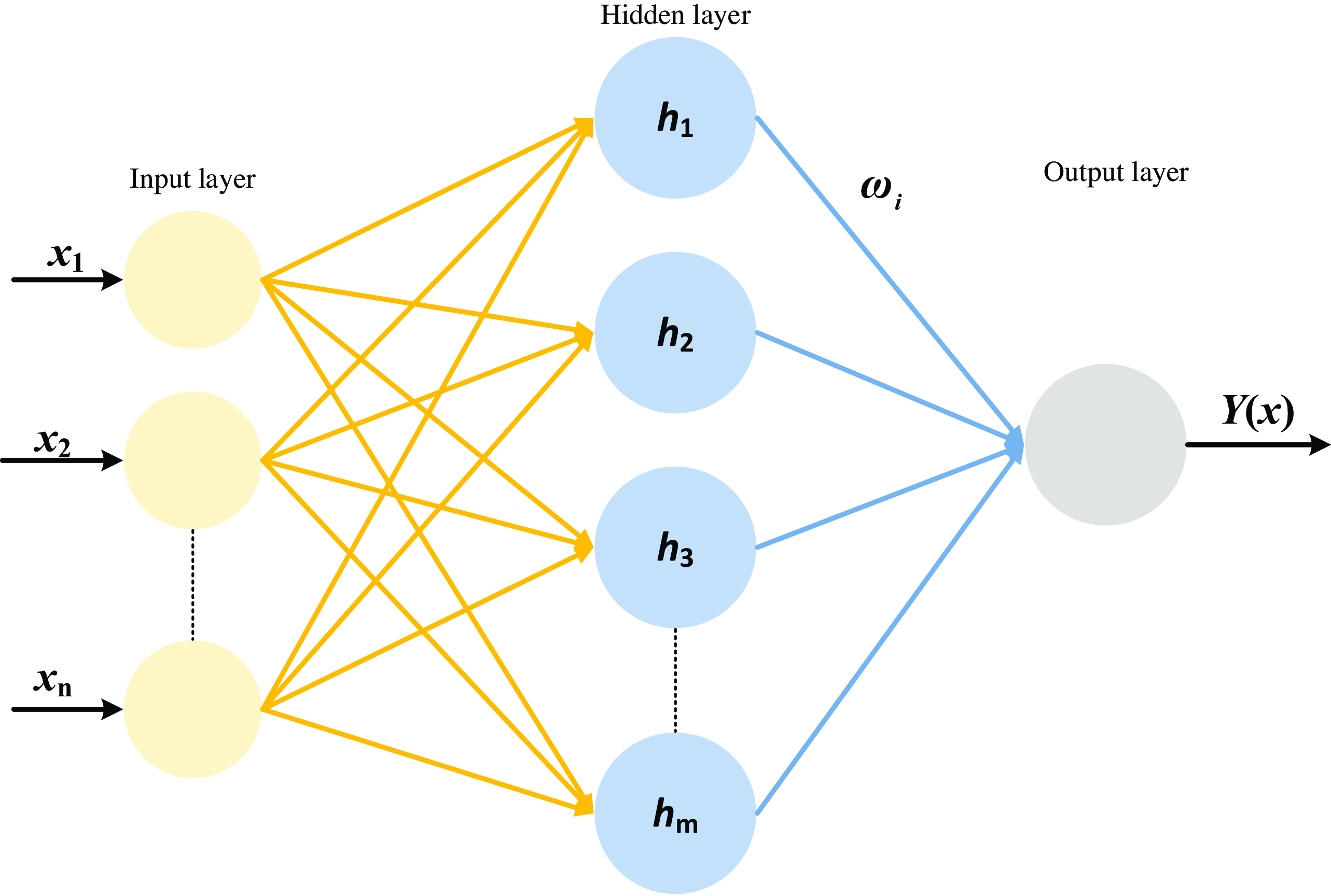
The output of the RBF-based ANN can be represented as:
 \begin{equation} \boldsymbol{Y}(\boldsymbol{x})=\boldsymbol{\omega }^{T}\cdot \boldsymbol{h}(\boldsymbol{x})+\boldsymbol{\varepsilon } \end{equation}
where
 $\boldsymbol{x}\boldsymbol{=}[\boldsymbol{e},\dot{\boldsymbol{e}}]^{T}$
and
 $\boldsymbol{Y}(\boldsymbol{x})$
are the neural network input and output, respectively.
 $\boldsymbol{\omega }^{T}$
is the weight matrix that connects the hidden layer and the output layer,
 $\boldsymbol{h}(\boldsymbol{x})$
is the nonlinear function of the hidden nodes, and
 $\boldsymbol{\varepsilon }$
is an approximation error of the neural network. The structure of the RBFNN-based ANN is shown in Figure 3. The input of the designed RBF includes the joint friction, parameter perturbation, and high-order unmodeled dynamics.
Structure of the RBFNN-based ANN.

A Gaussian fit is selected for the nonlinear function as follows:
 \begin{equation} \boldsymbol{h}(\boldsymbol{x})=\exp \left(-\frac{\left\| \boldsymbol{x}-\boldsymbol{\mu }_{i}\right\| ^{2}}{2\boldsymbol{\delta }_{i}^{2}}\right)i=1,2,\ldots, m \end{equation}
where
 $\boldsymbol{\delta }_{i}$
and
 $\boldsymbol{\mu }_{i}$
are the width and center of the Gaussian function, respectively.
According to Eq. (17), the uncertain term
 $\boldsymbol{f}(\boldsymbol{x})$
can be estimated by the RBF-based ANN as:
 \begin{equation} \overline{\boldsymbol{f}}(\boldsymbol{x})=\boldsymbol{\omega }_{f}^{T}\cdot \boldsymbol{h}_{f}(\boldsymbol{x})+\iota _{f} \end{equation}
where
 $\overline{\boldsymbol{f}}(\boldsymbol{x})$
is the absolute value of
 $\boldsymbol{f}(\boldsymbol{x}), \boldsymbol{\omega }_{f}^{T}$
is the weight matrix, and
 $\iota _{f}$
represents the estimation error.
The system uncertainty term can be estimated as:
 \begin{equation} \widehat{\overline{\boldsymbol{f}}}=\hat{\boldsymbol{\omega }}_{f}^{T}\boldsymbol{h}_{f}(\boldsymbol{x}) \end{equation}
Assumption 1:
 $\boldsymbol{\omega }_{f}^{*}$
is the optimal weight,
 \begin{equation} \forall \iota _{n}\gt 0,\overline{\boldsymbol{f}}-\boldsymbol{\omega }_{f}^{*}\boldsymbol{h}_{f}(\boldsymbol{x})=\iota _{f},\left\| \iota _{f}\right\| \lt \iota _{n} \end{equation}
Assumption 2:
 $\boldsymbol{\omega }_{f}^{*}$
is bounded,
 \begin{equation} \exists \boldsymbol{\omega }_{n}\gt 0,\left\| \boldsymbol{\omega }_{f}^{*}\right\| \leq \boldsymbol{\omega }_{n} \end{equation}
The original neural network needs to design multiple adaptive laws to estimate multiple parameters. To reduce the difficulty of parameter tuning, a novel adaptive law that only needs one parameter to obtain the lumped uncertainty is designed as follows:
 \begin{equation} \dot{\tilde{\boldsymbol{\omega }}}_{f}=-\dot{\hat{\boldsymbol{\omega }}}_{f}=-\eta _{f}\boldsymbol{h}_{f}(\boldsymbol{x})\boldsymbol{s} \end{equation}
where
 $\eta _{f}$
is a positive parameter,
 $\tilde{\boldsymbol{\omega }}_{f}=\boldsymbol{\omega }_{f}-\hat{\boldsymbol{\omega }}_{f}$
is the weight estimation error. To obtain the estimated value of
 $\boldsymbol{f}(\boldsymbol{x}), \eta _{f}$
is adjusted online to compensate for the uncertain factors in sliding mode control. The compensation input
 $\boldsymbol{T}_{nn}$
is defined as:
 \begin{equation} \boldsymbol{T}_{nn}=\hat{\boldsymbol{\omega }}_{f}^{T}\boldsymbol{h}_{f}(\boldsymbol{x}) \end{equation}
The control input of FNITSMC can be obtained as follows:
 \begin{equation} \boldsymbol{T}_{0}=\boldsymbol{T}_{smc}+\boldsymbol{T}_{nn} \end{equation}
The total control law can be obtained as:
 \begin{equation} \boldsymbol{T}_{0}=\hat{\boldsymbol{I}}(\boldsymbol{a})\left(\ddot{\boldsymbol{a}}_{d}+k_{m}\boldsymbol{s}+k_{n}\mathrm{sig}(\boldsymbol{s})+\boldsymbol{\varphi }_{i}\lambda _{i}\left(\boldsymbol{e}_{i},\gamma _{i},\rho _{i},\varepsilon _{i}\right)\right)+\hat{\boldsymbol{K}}(\boldsymbol{a},\dot{\boldsymbol{a}})\dot{\boldsymbol{a}}+\hat{\boldsymbol{G}}(\boldsymbol{a})+\hat{\boldsymbol{\omega }}_{f}^{T}\boldsymbol{h}_{f}(\boldsymbol{x}) \end{equation}
3.3. Stability analysis
For the stability analysis, the following lemmas are required:
Lemma 1: For a continuous positive definite Lyapunov function
 $V(t)$
, if
 $x=0, V(0)=0$
and
 $\forall x\neq 0$
, then
 $V(x)\gt 0$
. If
 $V(t)$
satisfies
 $V(x)\gt 0$
and
 $\dot{V}(x)\lt 0$
, it can be derived that
 $\| x\| \rightarrow \infty$
and
 $V(x)\rightarrow \infty$
. In this case, the nonlinear system is globally asymptotically stable.
Lemma 2: There is a continuous positive definite function
 $V(t)$
which satisfies:
 \begin{equation} \dot{V}(t)\leq -\alpha V^{\kappa }(t), V(0)=0 \end{equation}
where
 $\alpha \gt 0$
and
 $0\lt \kappa \lt 1$
are the designed constants.
A finite-time stable convergence time
 $t$
is calculated as:
 \begin{equation} t\leq \left[1/\alpha \left(1-\kappa \right)\right]\cdot V^{1-\kappa }\left(t_{0}\right) \end{equation}
where
 $t_{0}$
is the initial state time of the system. It can be inferred that the system satisfies the global finite-time stability.
Combining Eqs.(4), (19) and (26), the following equation can be obtained:
 \begin{equation} \boldsymbol{I}(\boldsymbol{a})\dot{\boldsymbol{s}}=-\boldsymbol{K}(\boldsymbol{a},\dot{\boldsymbol{a}})\boldsymbol{s}+\boldsymbol{\omega }_{f}^{T}\boldsymbol{h}_{f}(\boldsymbol{x})+\iota _{f}-\boldsymbol{T}_{0} \end{equation}
where
 $\iota _{f}$
is the estimation error of the existing neural network.
Construct the Lyapunov function:
 \begin{equation} V=\frac{1}{2}\boldsymbol{s}^{T}\boldsymbol{I}(\boldsymbol{a})\boldsymbol{s}+\frac{1}{2}\mathrm{trace}\left(\tilde{\boldsymbol{\omega }}_{f}^{T}\eta _{f}^{-1}\tilde{\boldsymbol{\omega }}_{f}\right) \end{equation}
where
 $\tilde{\boldsymbol{\omega }}_{f}=\boldsymbol{\omega }_{f}-\hat{\boldsymbol{\omega }}_{f}$
indicates the error matrix of the weights, and
 $\hat{\boldsymbol{\omega }}_{f}$
denotes the estimation of the weight matrix
 $\boldsymbol{\omega }_{f}$
. The derivative of the Lyapunov function is obtained as:
 \begin{equation} \dot{V}=\frac{1}{2}\boldsymbol{s}^{T}\dot{\boldsymbol{I}}(\boldsymbol{a})\boldsymbol{s}+\boldsymbol{s}^{T}\boldsymbol{I}(\boldsymbol{a})\dot{\boldsymbol{s}}+\mathrm{trace}\left(\tilde{\boldsymbol{\omega }}_{f}^{T}\eta _{f}^{-1}\dot{\tilde{\boldsymbol{\omega }}}_{f}\right) \end{equation}
Substituting Eqs. (23) and (29) into Eq. (31), it can be gained:
 \begin{equation} \begin{array}{c} \dot{V}=\frac{1}{2}\boldsymbol{s}^{T}\left[\dot{\boldsymbol{I}}(\boldsymbol{a})-2\boldsymbol{K}(\boldsymbol{a},\dot{\boldsymbol{a}})\right]\boldsymbol{s}+\mathrm{trace}\left(\tilde{\boldsymbol{\omega }}_{f}^{T}\eta _{f}^{-1}\dot{\tilde{\boldsymbol{\omega }}}_{f}\right)\\ +\boldsymbol{s}^{T}\left[\left(\hat{\boldsymbol{\omega }}_{f}^{T}\boldsymbol{h}_{f}(\boldsymbol{x})+\tilde{\boldsymbol{\omega }}_{f}^{T}\boldsymbol{h}_{f}(\boldsymbol{x})\right)+\iota _{f}-\boldsymbol{T}_{0}\right]\\ =-\boldsymbol{s}^{T}\hat{\boldsymbol{I}}(\boldsymbol{a})\left(k_{m}\boldsymbol{s}+k_{n}\mathrm{sig}(\boldsymbol{s})+\boldsymbol{\varphi }_{i}\lambda _{i}\left(\boldsymbol{e}_{i},\gamma _{i},\rho _{i},\varepsilon _{i}\right)\right)+\boldsymbol{s}^{T}\iota _{f}\\ -\boldsymbol{s}^{T}\left[\hat{\boldsymbol{I}}(\boldsymbol{a})\ddot{\boldsymbol{a}}_{d}+\hat{\boldsymbol{K}}(\boldsymbol{a},\dot{\boldsymbol{a}})\dot{\boldsymbol{a}}+\hat{\boldsymbol{G}}(\boldsymbol{a})\right]\\ =-\boldsymbol{s}^{T}\hat{\boldsymbol{I}}(\boldsymbol{a})\left(k_{m}\boldsymbol{s}+k_{n}\mathrm{sig}(\boldsymbol{s})\right)+\boldsymbol{s}^{T}\iota _{f}\\ -\boldsymbol{s}^{T}\left[\hat{\boldsymbol{I}}(\boldsymbol{a})\left(\ddot{\boldsymbol{a}}_{d}+\boldsymbol{\varphi }_{i}\lambda _{i}\left(\boldsymbol{e}_{i},\gamma _{i},\rho _{i},\varepsilon _{i}\right)\right)+\hat{\boldsymbol{K}}(\boldsymbol{a},\dot{\boldsymbol{a}})\dot{\boldsymbol{a}}+\hat{\boldsymbol{G}}(\boldsymbol{a})\right] \end{array} \end{equation}
Defining
 $\boldsymbol{R}=\hat{\boldsymbol{I}}(\boldsymbol{a})(\ddot{\boldsymbol{a}}_{d}+\boldsymbol{\varphi }_{i}\lambda _{i}(\boldsymbol{e}_{i},\gamma _{i},\rho _{i},\varepsilon _{i}))+\hat{\boldsymbol{K}}(\boldsymbol{a},\dot{\boldsymbol{a}})\dot{\boldsymbol{a}}+\hat{\boldsymbol{G}}(\boldsymbol{a})$
, Eq. (32) can be obtained as follows:
 \begin{equation} \begin{split} \dot{V} &\leq -\boldsymbol{s}^{T}\left(\hat{\boldsymbol{I}}(\boldsymbol{a})\ddot{\boldsymbol{a}}+\hat{\boldsymbol{K}}(\boldsymbol{a},\dot{\boldsymbol{a}})\dot{\boldsymbol{a}}+\hat{\boldsymbol{G}}(\boldsymbol{a})\right)\\ &\leq -\boldsymbol{s}^{T}\left(\boldsymbol{T}_{0}-\boldsymbol{F}\right)\\ &\leq -\sum _{i=1}^{n}\left| \boldsymbol{s}_{i}\right| \int \left(\left| \dot{\boldsymbol{T}}_{0}\right| -\left| \dot{\boldsymbol{F}}\right| \right)\mathrm{d}t\\ &\leq 0 \end{split} \end{equation}
Furthermore, define
 $V_{t}=\frac{1}{2}\boldsymbol{s}^{T}\boldsymbol{I}(\boldsymbol{a})\boldsymbol{s}$
. Since the Gauss function Eq. (18) is bounded at [0,1],
 $k_{m}\gt k_{f}$
. It can derive the following function:
 \begin{equation} \begin{split} \dot{V}_{t}&=-\boldsymbol{s}^{T}k_{m}\boldsymbol{s}-\boldsymbol{s}^{T}k_{n}\mathrm{sig}(\boldsymbol{s})+\boldsymbol{s}^{T}\tilde{\boldsymbol{\omega }}_{f}^{T}\boldsymbol{h}_{f}(\boldsymbol{x})+\boldsymbol{s}^{T}\iota _{f}\\ &\leq -\boldsymbol{s}^{T}k_{m}\boldsymbol{s}-\left\| \boldsymbol{s}\right\| k_{n}+\boldsymbol{s}^{T}k_{f}\boldsymbol{s}\\ &\leq -\boldsymbol{s}^{T}\left(k_{m}-k_{f}\right)\boldsymbol{s}\\ &\leq 0 \end{split} \end{equation}
Therefore, Eq. (34) can be rewritten as
 $\dot{V}_{1}\leq -cV^{1/2},c=k_{n}$
. According to
Lemma 2, the convergence time of the system satisfies:
 $t_{r}\leq (2V_{1}(0))^{1/2}/c$
.
The stability and convergence of the ANN-FNITSMC in finite time are proofed.
4. Simulations and experiments
In this section, Simulink in MATLAB is employed to evaluate the effectiveness of ANN-FNITSMC in comparison with FNITSMC and TSMC. For simulation studies, the diameter of the bone disk is set to 6 cm, the flexible support length
 $l$
is 30 cm, and the material parameters are specified as E = 210 Gpa, G = 80 Gpa, and ρ = 8000 kg m-3. The initial position vector of the CDCR in the global frame is set as
 $[0,0,l]^{T}$
. The sampling period is 0.05 s, and the sampling continuous time is 5 s. The control parameters are
 $\lambda _{1}=1/9, \lambda _{2}=1/5, \rho _{1}=\rho _{2}=5, \eta _{1}=\eta _{2}=15, \varepsilon _{1}=\varepsilon _{2}=0.1, k_{m}=20, k_{n}=5$
. The control parameters are simplified compared to Eq. (10), which requires multiple constraints of 1<p/q<2, and m/n>p/q. According to Eqs. (17)–(18), the initial weights of the neural networks should be randomly selected as follows:
 \begin{equation*} \mu =\left[\begin{array}{l@{\ \ \ \ }l@{\ \ \ \ }l@{\ \ \ \ }l@{\ \ \ \ }l@{\ \ \ \ }l@{\ \ \ \ }l} -1.5 & -1 & -0.5 & 0 & 0.5 & 1 & 1.5\\ -1.5 & -1 & -0.5 & 0 & 0.5 & 1 & 1.5\\ -1.5 & -1 & -0.5 & 0 & 0.5 & 1 & 1.5\\ -1.5 & -1 & -0.5 & 0 & 0.5 & 1 & 1.5\\ -1.5 & -1 & -0.5 & 0 & 0.5 & 1 & 1.5 \end{array}\right]\delta _{i}=10,i=1,2,\cdot \cdot \cdot, 7 \end{equation*}
4.1. Simulations of the RBF-based ANN
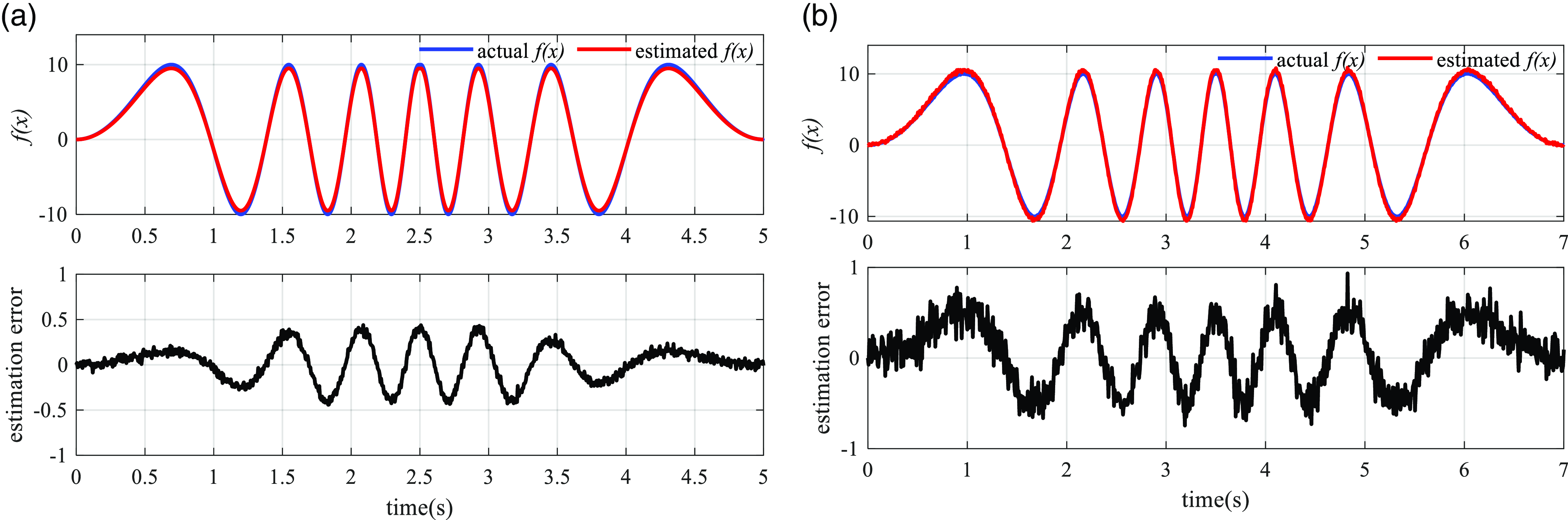
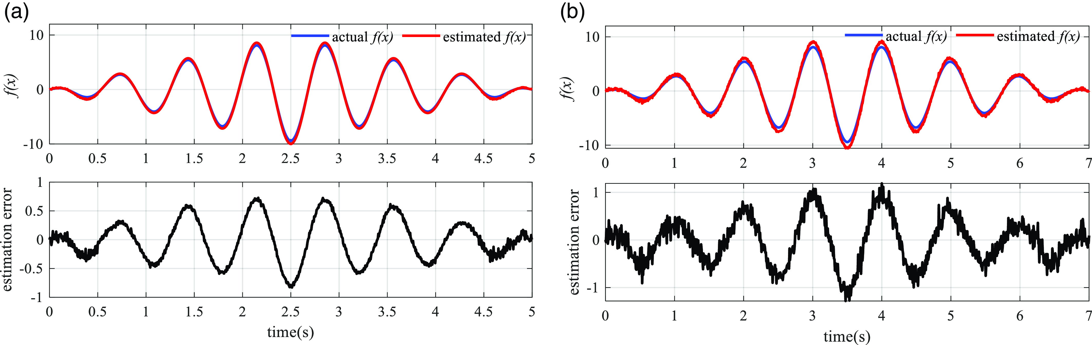
The estimation capability of the proposed ANN method is validated in this subsection. A nonlinear function with time-varying frequency and a nonlinear function with time-varying amplitude are selected as the typical uncertain dynamics of CDCRs to test the estimation accuracy of ANN. As a method similar to the RBF-based ANN, back propagation neural network (BPNN) [Reference Nguyen, Nguyen, Ha, Tuan, Ngoc and Sung32] is used to compare with the designed ANN. The curves of the nonlinear functions and the corresponding estimation results are shown in Figure 4 and Figure 5. It can be seen that the estimation errors of ANN are consistently limited within a narrow range of ±0.5 on average, while the estimation errors of BPNN are within an average range of ±0.8. These curves demonstrate that the designed ANN can achieve higher accuracy and stronger robustness of uncertainties estimation in comparison with BPNN.
The estimated value with time-vary frequency. (a) The estimated value of RBFNN; (b) The estimated value of BPNN.

The estimated value with time-vary amplitude. (a) The estimated value of RBFNN; (b) The estimated value of BPNN.

4.2. Simulations of circular trajectory tracking
The desired circular trajectory is designed as follows:
 \begin{equation} \left\{\begin{array}{l} x_{d}=20\times \cos ({\unicode[Arial]{x03C0}} /50\times t)\\ y_{d}=20\times \sin ({\unicode[Arial]{x03C0}} /50\times t)\\ z_{d}=10 \end{array}\right. \end{equation}
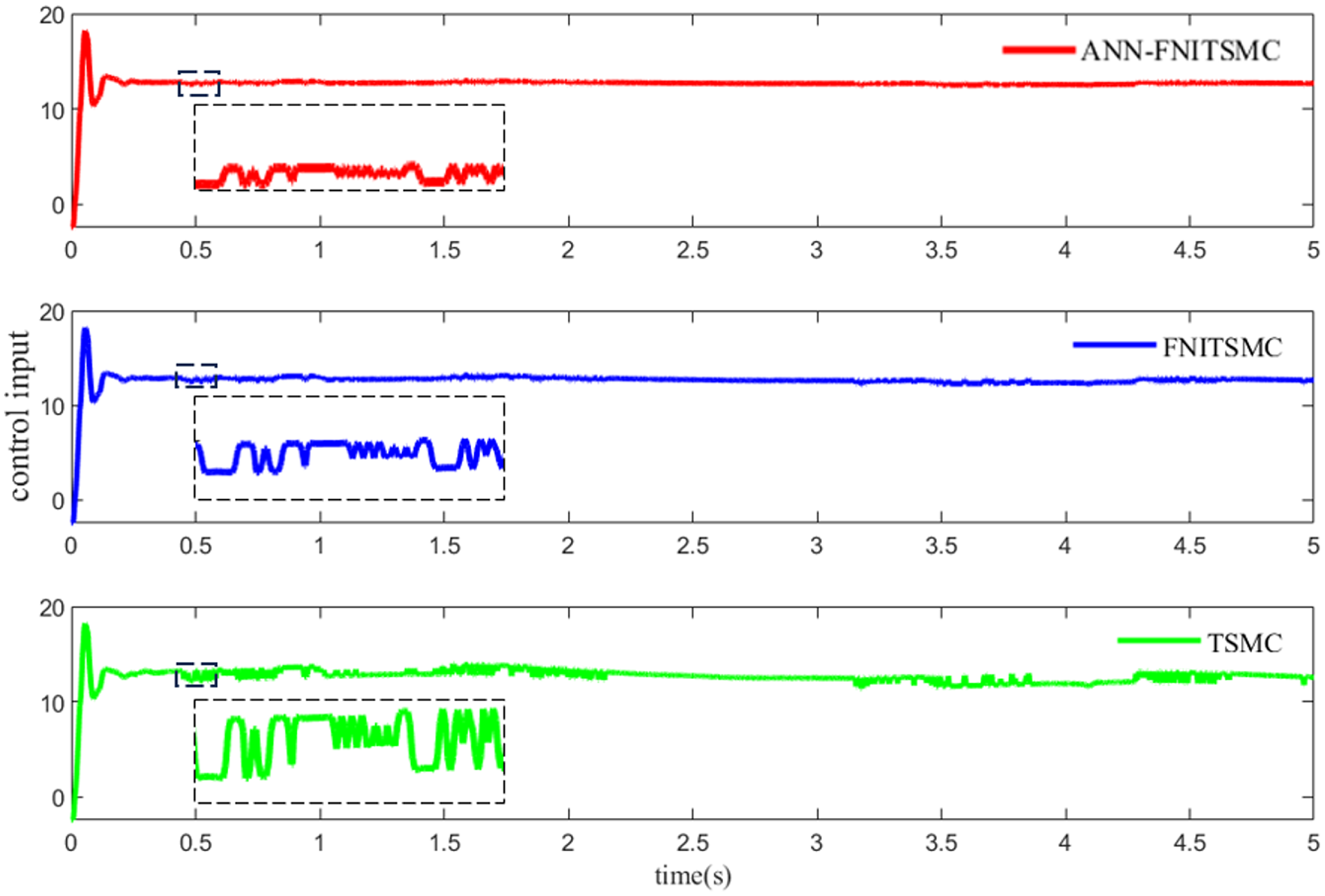
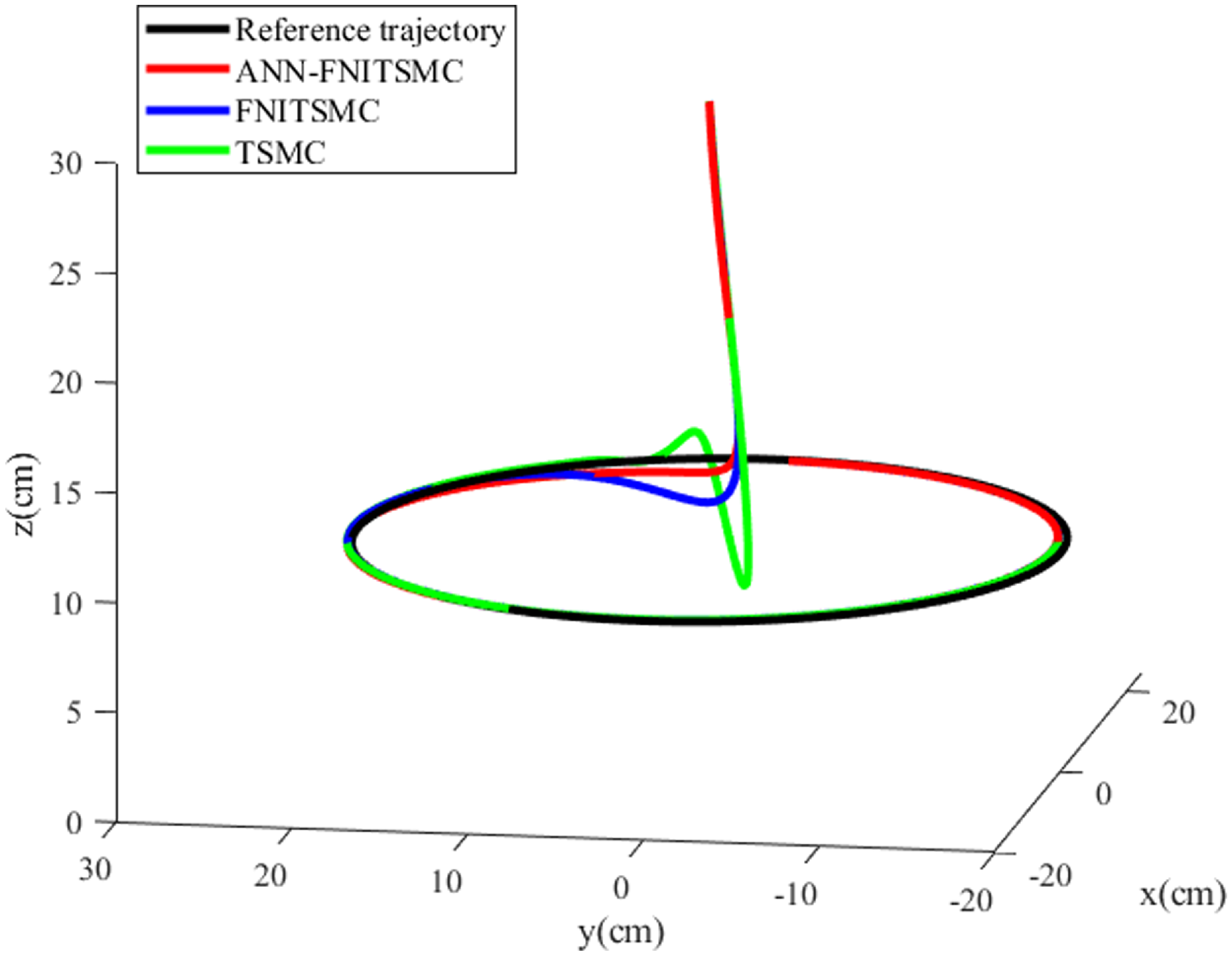
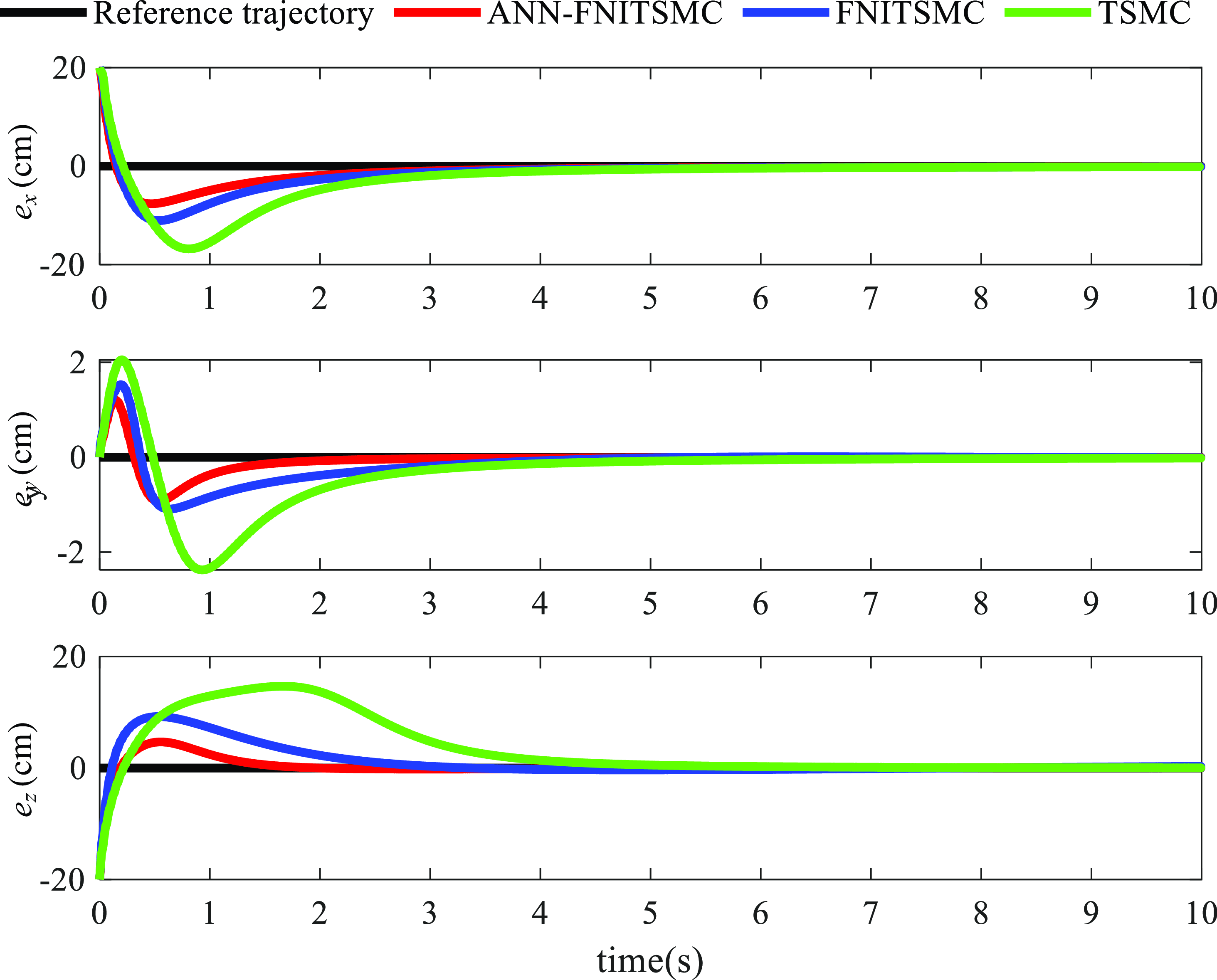
The tracking results and tracking errors of the CDCR by using ANN-FNISMC, FNITSMC, and TSMC are depicted in Figure 6 and Figure 7, respectively. The peak error of ANN-FNITSMC is around 0.8 cm, which is lower than those of FNITSMC and TSMC by 0.3 cm and 1 cm, respectively. Moreover, ANN-FNITSMC demonstrates a faster convergence speed in comparison with the other two methods. Additionally, the control inputs of these three controllers are shown Figure 8. It is evident that the curve representing ANN-FNISMC is smoother than those of other controllers, indicating that ANN-FNISMC has a more stable control input which can suppress the chattering more effectively than other methods. The tracking errors of ANN-FNITSMC, FNITSMC, and TSMC are also listed in Table I. The absolute average tracking errors of ANN-FNITSMC, FNITSMC, and TSMC are 0.1093 cm, 0.1437 cm, and 0.1846 cm, respectively. Compared with FNITSMC and TSMC, the average tracking errors of ANN-FNITSMC are reduced by 31.49% and 68.87%, respectively. The simulation results indicate that the proposed ANN-FNITSMC controller can mitigate the chattering and improve tracking accuracy.
The circular trajectory tracking results of these three controllers in three dimensions.

The circular trajectory tracking errors of these three controllers.

Control inputs of these three controllers for circular trajectory.

Comparison results of these three controllers for circular trajectory.

4.3. Simulations of spiral trajectory tracking
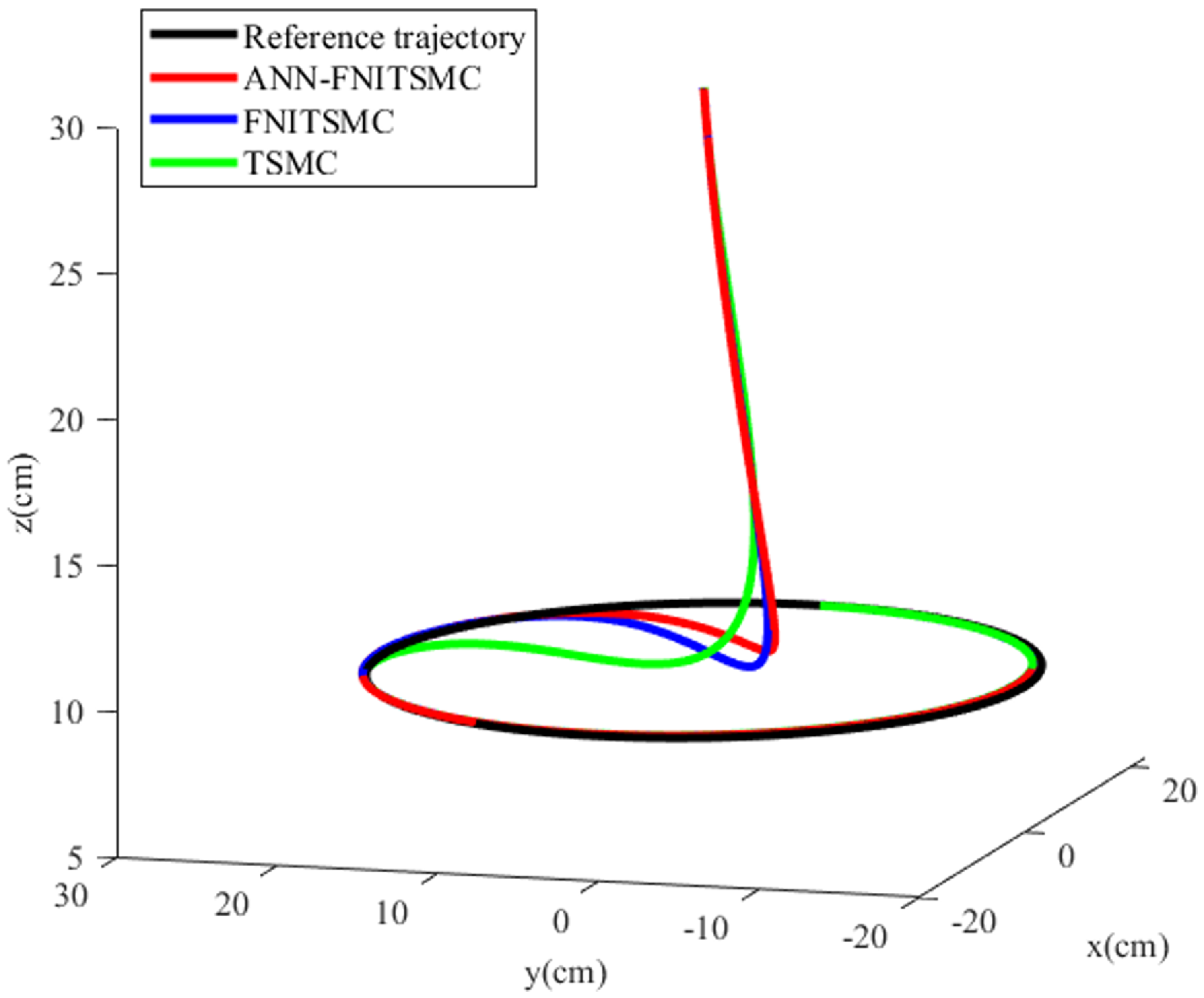
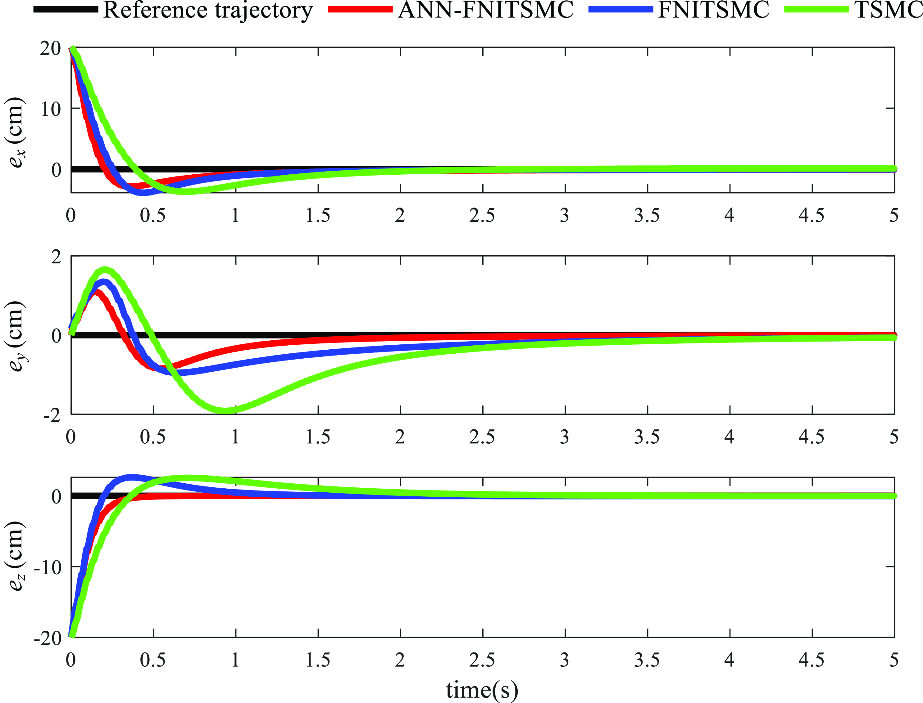
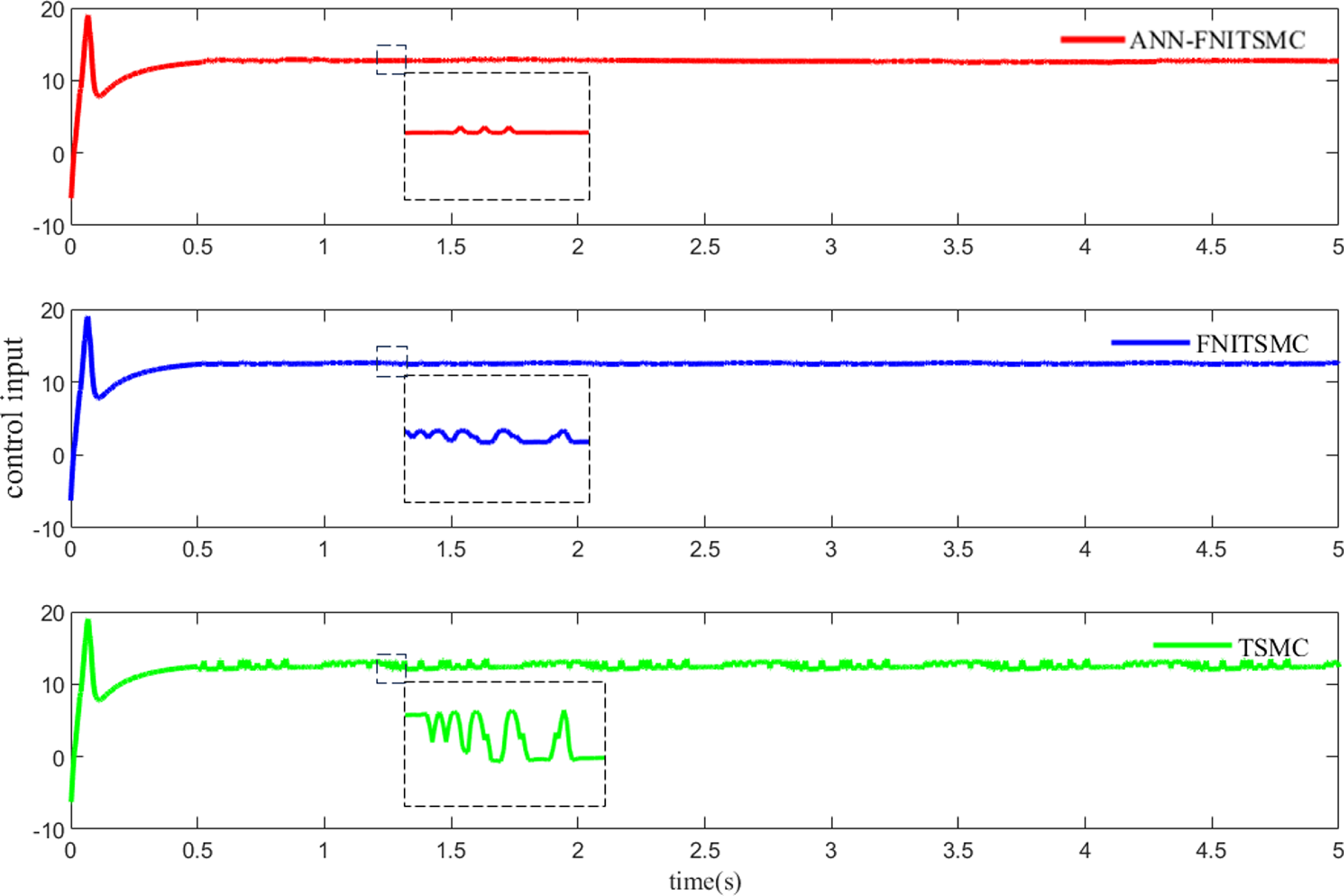
To further verify the tracking performance of ANN-FNISMC for 3D trajectories, a spiral trajectory presented as Eq. (36) is tracked by ANN-FNITSMC, FNITSMC, and TSMC with the same parameter settings in the circular trajectory.
 \begin{equation} \left\{\begin{array}{l} x_{d}=2/11\times \left(t+20\right)\times \cos(0.8\times t)\\ y_{d}=5+2/11\times \left(t+15\right)\times \sin (0.8\times t)\\ z_{d}=25-0.1\times \left(t+20\right) \end{array}\right. \end{equation}
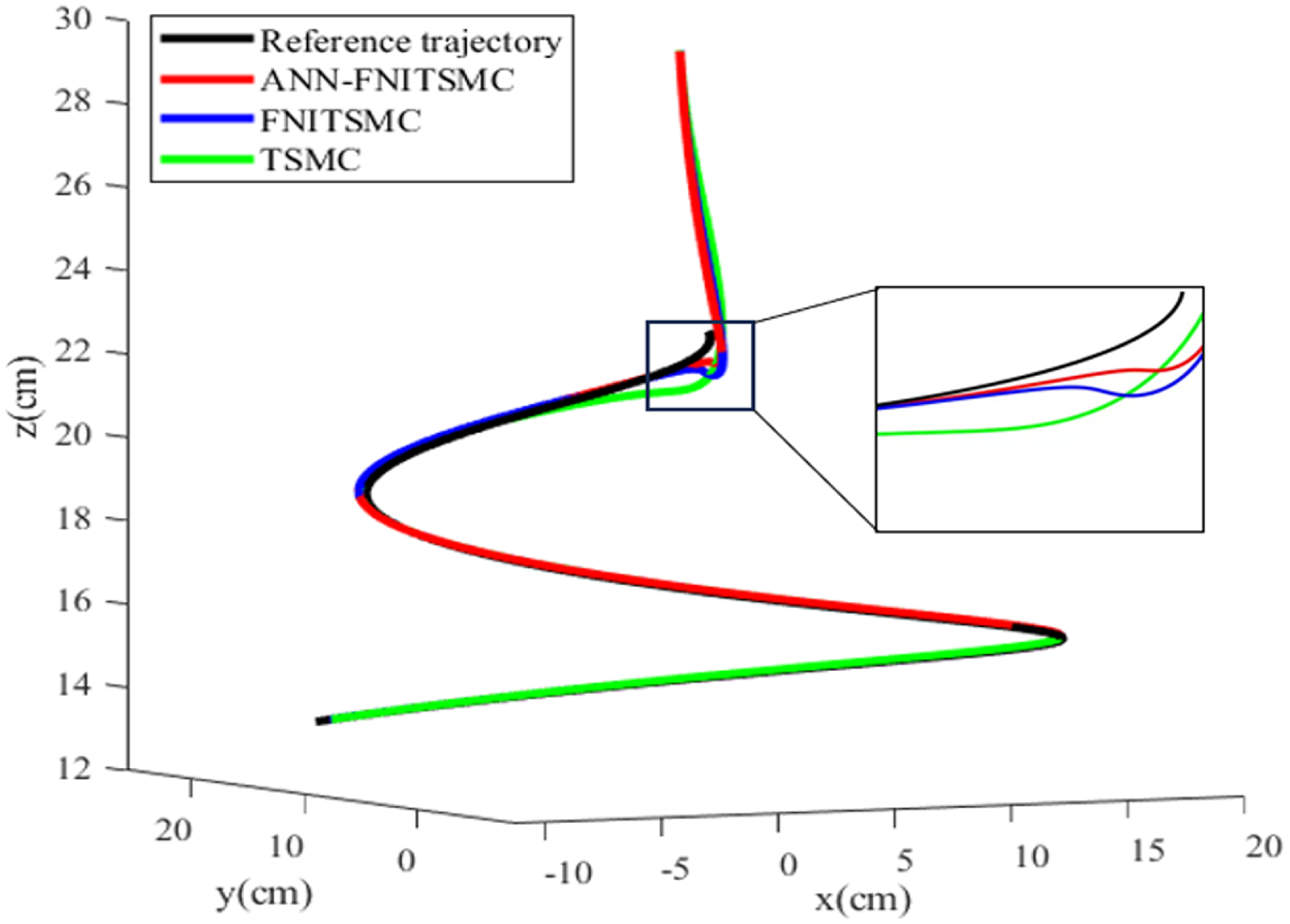
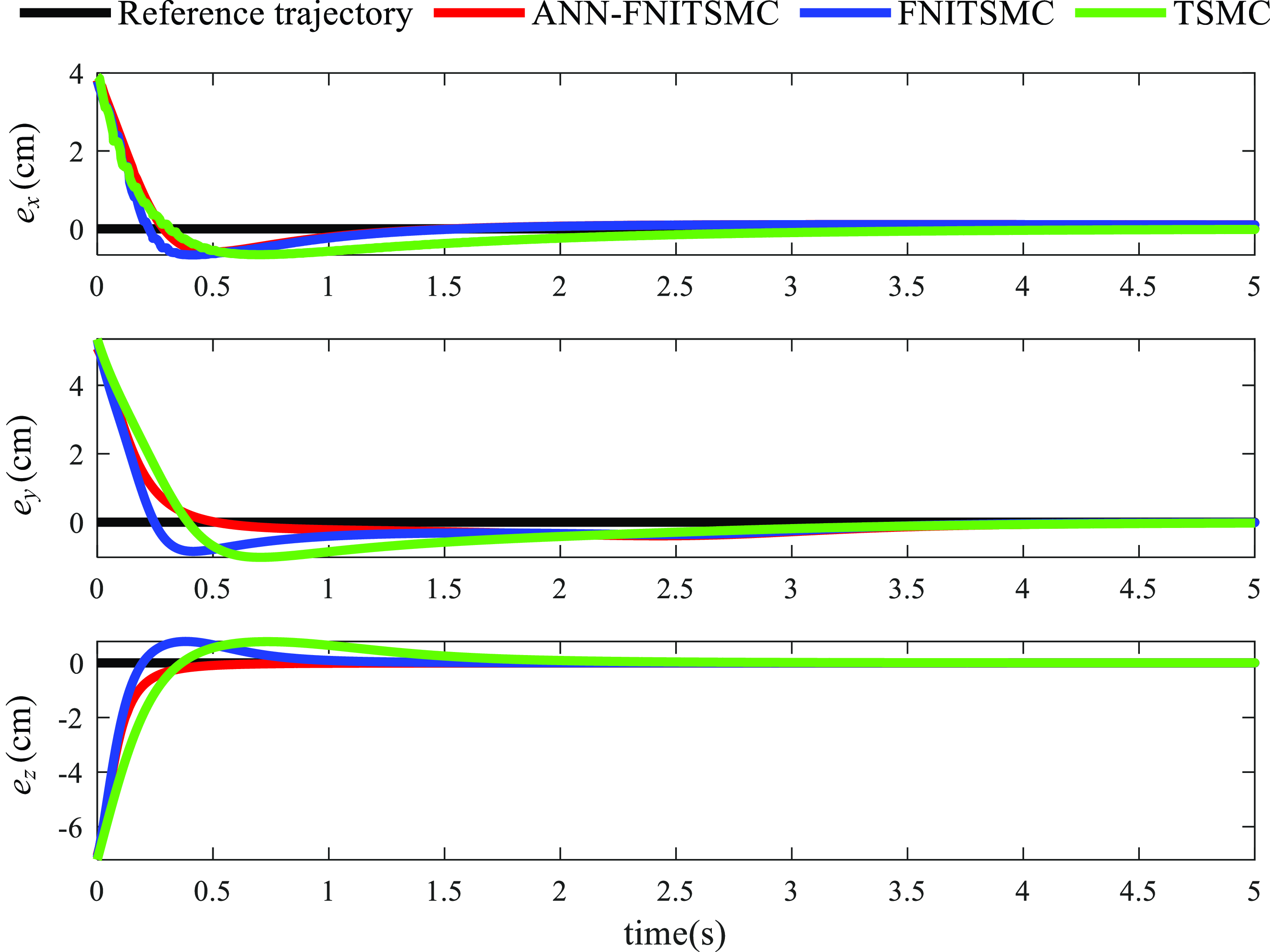
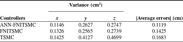
Figure 9 and Figure 10 show the spiral trajectory tracking results and tracking errors of these three controllers, respectively. The maximum tracking error of ANN-FNISMC is 0.2 cm, which is 0.3 cm and 0.5 cm lower than those of the other two methods respectively, indicating that ANN-FNISMC has higher tracking accuracy for a 3D trajectory. Moreover, the ANN-FNITSMC has a faster convergence rate than the other two methods. Figure 11 shows the control input of these three controllers. It can be seen that ANN-FNISMC has a smoother control input in comparison with the other methods, proving that ANN-FNISMC has a great chattering suppressing ability. The tracking errors of these three controllers are also listed in Table II. The absolute average tracking errors of ANN-FNITSMC, FNITSMC, and TSMC are 0.1119 cm, 0.1201 cm, and 0.1795 cm, respectively. Compared with FNITSMC and TSMC, the average tracking errors of ANN-FNITSMC are reduced by 27.33% and 50.41%, respectively. The spiral trajectory tracking results also indicate that the proposed ANN-FNITSMC controller has a better tracking performance for complex trajectories.
The spiral trajectory tracking results of these three controllers in three dimensions.

The spiral trajectory tracking errors of these three controllers.

Control inputs of these three controllers for spiral trajectory.

Comparison results of these three controllers for spiral trajectory.

4.4. Underwater experiments
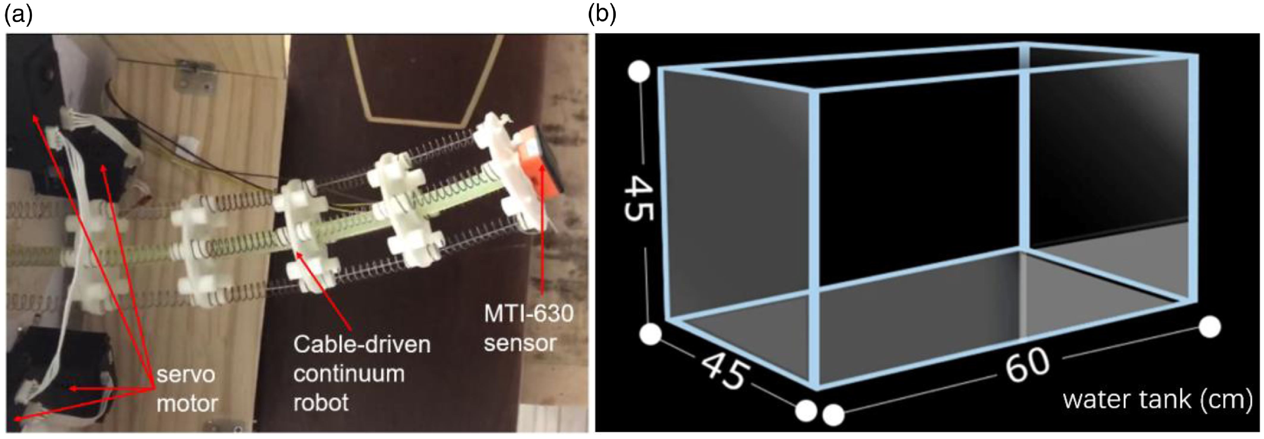
To assess the tracking performance of ANN-FNITSMC in an underwater environment, a real experiment has been carried out using a 60 cm × 45 cm × 45 cm tank. The experimental platform is shown in Figure 12. The CDCR system consists of a flexible rubber backbone, an MTI-630 sensor fixed at the end of the CDCR (The double-integration of the acceleration measured from the MTI-630 sensor is processed by the Extended Kalman Filter, which can reduce the estimated error of position and provide reliable motion data for trajectory tracking), four anti-rotation drive cables (high-strength polyethylene fiber cables), four servo motors (QDD Plus-NU80-6; reduction ratio, 6:1; maximum torque, 6 N · m; rated full-load speed, 200 rpm), six joint disks and 20 stainless steel springs. The rubber backbone is 30 cm long and 1 cm in diameter, providing bending stiffness for the robot. The joint disk is 30 cm in diameter and 1 cm in thickness. Each joint disk has eight evenly distributed circular holes with a diameter of 0.5 cm to serve as the stretching channel for the drive cables. The servo motors are evenly distributed on the bottom. The MTI-630 sensor with a directional error of less than 0.5 degrees can be used to calculate the real-time motion trajectory of the robot.
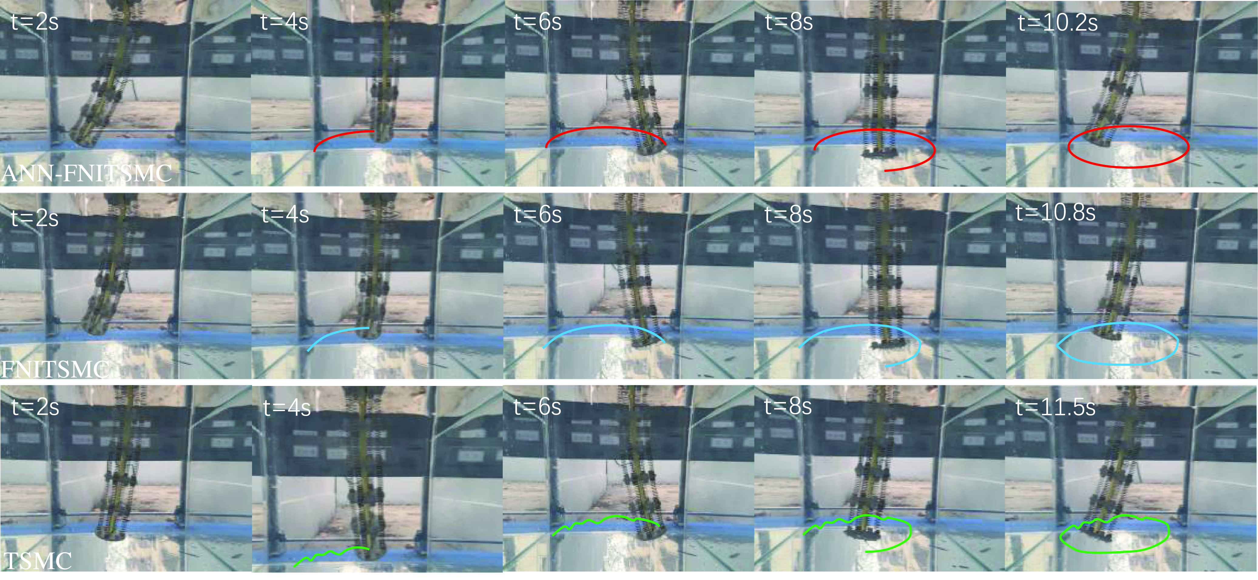
The time traces of ANN-FNITSMC, FNITSMC, and TSMC for the circular trajectory are shown in Figure 13. All these three controllers start tracking at t = 2 s. The complete time of ANN-FNITSMC, FNITSMC, and TSMC are 10.2 s, 10.8 s, and 11.5 s, respectively, which demonstrate that ANN-FNITSMC can also reduce convergence time due to its great chattering suppress ability. The tracking results and tracking errors are shown in Figure 14 and Figure 15, respectively. It can be seen that ANN-FNITSMC has a more stable and accurate tracking performance in comparison with the other two methods. The peak value of ANN-FNITSMC is around 1.2 cm, which is lower than those of FNITSMC and TSMC by 0.5 cm and 1.1 cm, respectively.
The comparison of experiment performance.

Cable-driven continuum robot experiment platform. (a) the prototype of the CDCR; (b) the tank for underwater experiment.

The CDCR underwater motion time trace.

The trajectory tracking results of these three controllers.

The tracking errors of the experiment.

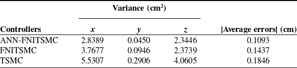
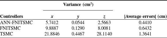
The tracking errors are quantified as the variance and average errors, which are shown in Table III. It can be seen that the variance and average error of ANN-FNITSMC are significantly lower than those of the other two controllers. Compared to FNITSMC and TSMC, the average tracking error of ANN-FNITSMC is reduced by 31.44% and 67.67%, respectively. The experiment results prove that ANN-FNITSMC achieves accurate and fast tracking performance in the underwater environment due to its great ability in solving singularity, chattering, and uncertainties.
5. Conclusion
In this paper, a novel ANN-FNITSMC is designed to achieve fast, accurate, stable, and robust trajectory tracking performance of the CDCR in complex underwater environments. FNITSMC can avoid the singularity, alleviate the chattering, and improve the tracking accuracy. Additionally, the RBF-based ANN is designed to estimate uncertainties, allowing for high accuracy and strong robustness in complex underwater application scenarios. Compared with FNITSMC and TSMC, ANN-FNITSMC exhibits a reduction in average errors by 30.43% and 63.66%, respectively. Both numerical simulation and underwater experiment results indicate that the proposed ANN-FNITSMC controller can achieve effective chattering suppression, strong robustness, and high-stable tracking accuracy. In the future, we will consider the collaborative work problem of multiple CDCRs in complex application scenarios.
Author contributions
Qi Chen and Chengjun Ming conceived and designed the study. Chengjun Ming and Yanan Qin analyzed the data. Chengjun Ming and Qi Chen wrote the article, Qi Chen and Yanan Qin revised and polished the article.
Financial support
This work was supported by the National Nature Science Foundation of China under Grant 52127813 and 52471336.
Competing interests
The authors declare no conflicts of interest exist.
Ethical approval
None.