INTRODUCTION
The laser mega joule (LMJ) facility, under construction near Bordeaux in France and the National Ignition Facility (NIF) at Livermore in California are being built to study fusion by inertial confinement (Besnard, Reference Besnard2007; Sangster, Reference Sangster2007). Both facilities will be equipped with about 200 laser beams that will focus on a 2 mm diameter cryogenic target filled with a Deuterium Tritium (DT) mixture. The target is held by a cold grip situated at the end of 6 m in length carbon boom. When inertial fusion is proved with these facilities, it will be necessary to prove that it is possible to shoot on several targets each second to produce the energy of a power plant. For this reason, target technology and delivery techniques are a key issue for the success of inertial fusion energy. Many groups in the world are working on these topics in many countries (Chatain et al., Reference Chatain, Perin, Bonnay, Bouleau, Chichoux, Communal, Manzagol, Viargues, Brisset, Lamaison and Paquignon2008; Deutsch et al., Reference Deutsch, Bret, Firpo, Gremillet, Lefebvre and Lifschitz2008; Foldes & Szatmari, Reference Foldes and Szatmari2008; Hoffmann, Reference Hoffmann2008; Kline et al., Reference Kline, Montgomery, Rousseaux, Baton, Tassin, Hardin, Flippo, Johnson, Shimada, Yin, Albright, Rose and Amiranoff2009; Rodriguez et al., Reference Rodriguez, Florido, Gll, Rubiano, Martel and Minguez2008; Romagnani et al., Reference Romagnani, Borghesi, Cecchetti, Kar, Antici, Audebert, Bandhoupadjay, Ceccherini, Cowan, Fuchs, Galimberti, Gizzi, Grismayer, Heathcote, Jung, Liseykina, Macchi, Mora, Neely, Notley, Osterholtz, Pipahl, Pretzler, Schiavi, Schurtz, Toncian, Wilson and Will2008; Seifter et al., Reference Seifter, Kyrala, Goldman, Hoffman, Kline and Batha2009; Strangio et al., Reference Strangio, Caruso and Aglione2009; Winterberg, Reference Winterberg2008).
For the LMJ, the targets are hollow spheres filled by permeation at ambient temperature then cooled down under the triple point of the DT mixture (19.79 K). Before the shot, the temperature must be controlled within stability better than ±2 mK, and the positioning must be performed with a precision better than 5 µm.
The cryogenic targets are filled and cooled down in the CEA of Valduc then transported, with their thermal shroud, to Bordeaux (CEA CESTA) in a specific cryostat that contains six targets at a temperature between 22 and 30 K. Then, they are taken off the cryostat to be transferred with a transfer robot (still with their thermal shroud) to the cryogenic target positioner. After conformation of the solid DT layer, which can last several hours, the cryogenic target positioner drives the target to the center of the 10 m in diameter vacuum vessel. Here, the shroud is slowly disengaged of the target base by the shroud remover situated at the opposite port of the cryogenic target positioner. During this phase, the temperature of the target must not vary more than ±2 mK. Then, the accurate alignment of the target is performed and just before the laser shot, the shroud must be removed very quickly (0.5 m in 0.1 s). This concept, proposed by our laboratory 10 years ago, caused some technologic problems. For this reason, a large program for the development of prototypes was initiated to validate some technical solutions chosen.
FILLING AND TRANSFER
Filling
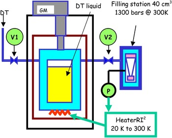
Filling of the LMJ target is carried out by permeation through the wall of the micro balloon (sphere). To have the desired quantity of DT, the pressure of the sphere must reach 1000 and 1500 bars at 300 K. To prevent breakage of the targets due to the effect of the pressure, the pressure difference between the internal and external walls must be less than 1 bar. To generate the pressure, a DT mixture is first liquefied in a small volume in connection with the permeation cell maintained at 300 K (Fig. 1). Then this small volume is heated from 20 K to 300 K by controlling the temperature on the wall. This system is able to limit the rise in pressure (ΔP on the micro balloon) and it is possible today to provide periods of filling that can vary from 4 to 48 h (filling rates from 0.5 to 6 bars/min). The system is intrinsically safe because it does not have any moving parts as compared to piston compressors. Moreover, when the system is left alone (simulation of a loss of the control system) the increase in temperature with the natural losses of the system allows a pressure of only 400 bars (Viargues et al., Reference Viargues, Chatain and Perin2002).
(Color online) Principle of the cryocompressor.

Transfer
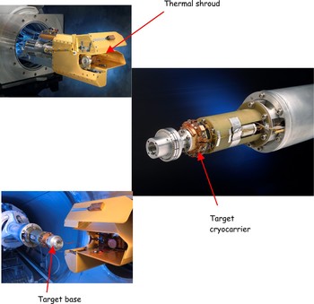
After filling the targets they are cooled close to 25K to reduce the pressure inside of the microballoon and to prevent from bursting. For this reason, the target must be handled by cryogenic tools (grip) under vacuum and at low temperatures (Fig. 2). The design of such a tool is a real challenge. These grips must provide two important functions: the transfer of heat (power dissipated and radiation heat load) and the transfer of information. The coating of surfaces was studied in order to obtain thermal resistances of contact between the target and the grip as low as possible. This point is extremely important, because the temperature achieved is related to this thermal resistance, as well as the required size of the cold source, and its ultimate temperature. Indeed, if this thermal resistance is bad (3 K/W), maintaining the target at 19 K will require the cold grip to be at a lower temperature, thus increasing the power, the price, and the size envelope of the cold source. During transfers the temperature of the target must be known, it is necessary that the grip provides reliable electrical contacts, and thus must be free from any trace of contamination. This requires transfer under stringent vacuum conditions. Current operations are setup to provide these conditions and this criterion of thermal resistance. The “Service des Basses Temperatures” (SBT) undertook a research program on this subject and today SBT is able to carry out thermal contacts of low resistance (1 K/W) at 17 K. The cryogenic grip is a key point of the cryogenic system. Its development required several years and will still require improvements. It is one of the most important technological advances that was necessary to be solved (Paquignon et al., Reference Paquignon, Manzagol, lamaison, Brisset, Chatain, Bonnay, Bouleau, Communal and Périn2006).
(Color online) Cryogrip and transfer.

THERMAL REGULATION
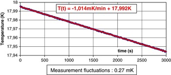
Temperature control objectives were achieved by developing control systems based on synchronous detection and “multivariable” algorithm. These algorithms make it possible to control based on several data inputs as well as possible to adjust the parameters of control (Fig. 3). Moreover, this technique allows simple in-situ tests for the true physical values of the variables to be introduced into the software. This software is not very sensitive to the environmental disturbances that are encountered in quasi industrial installations like the LMJ. This thermal control (0.2 mK at 20 K) and the cooling of the target with a speed of 1 mK/min will ensure the physicists a powerful tool to reach the necessary geometric characteristics of the ice layer (Lamaison et al., Reference Lamaison, Brisset, Cathala, Paquignon, Bonnay, Chatain, Communal and Périn2004).
(Color online) Grip temperature during layering.

THERMAL SHROUD
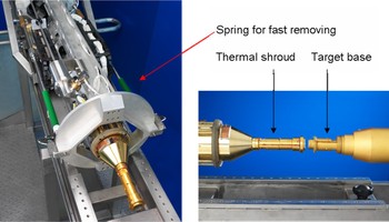
The last important advance to be solved is the removal of the thermal shroud (Fig. 4). During all handling, from its filling to the shooting, the target is protected from the surrounding thermal radiation by a cooled shroud that must be withdrawn very quickly before the shot. When the target is exposed to the chamber radiation, its lifetime is only 180 ms. The problems are complex; the removal of the thermal shroud should not generate vibrations with an amplitude greater than 5 µm on the targets, and the thermal field around the target should not vary more than 10 mK. Studies have focused on the coupling of two cold sources and on the procedures for alignment of the two arms (the target carrier and shroud carrier in the experimental chamber). A model of this unit has been brought into service during 2007 and demonstrated meeting its requirements (Chatain et al., Reference Chatain, Lamaison, Bonnay, Bouleau and Périn2006).
(Color online) A view of the thermal shroud remover prototype.

As shown on the Figure 4, the shroud extraction will be performed with a specific device situated at the opposite port of the cryogenic target positioner. It is composed of a 6 m carbon boom at the end of which a hexapod is fixed. The extraction device is fixed on the mobile part of the hexapod; it is equipped with a cryogenic grip. The extraction is performed in two steps: the first step consists in disengaging slowly the shroud from the target base; the second step consists in the fast extraction just before the shot. During the first phase, the movement must be very slow because the temperature of the target must not vary more than 2 mK. During the second phase, the displacement has to be of 0.5 m within 100 ms. This is achieved with two springs.
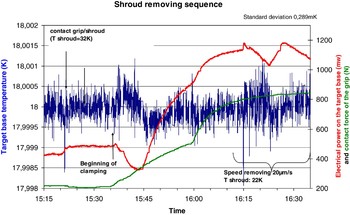
Keeping the temperature stability during the gripping and removing phases of the shroud are difficult points. It was decided to build a prototype to test technical solutions. This prototype operates since the spring of 2007. Many experiments have already been performed. The temperature stability at ±2 mK during the gripping and removing phases of the shroud was obtained (Fig. 5). The following method was used: (1) Control of the target base temperature at 18 K ±1 mK by adjusting the helium flow rate in the heat exchanger of the target grip (a flow rate of 2300 NL/h is necessary) and by acting on the heater of the target base. At this time the shroud temperature is about 32 K (about 1.2 W (radiation) falls on the shroud and the thermal contact resistance between the shroud and the target base is about 12 K/W at 20 K). (2) The temperature of the shroud remover grip is stabilized at the same temperature as that of the shroud then the shroud remover is slowly approached. (3) The shroud grip catches the shroud very slowly. This operation lasts about 10 min. The final clamping force is 800 N and the slope is around 10 N min−1. (4) The shroud grip temperature is slowly decreased, we obtain 18 K. (5) The shroud is removed at a speed of 20 µm/s.
(Color online) Temperature stability of the target base during the shroud removing.

CRYOGENIC INFRASTRUCTURE
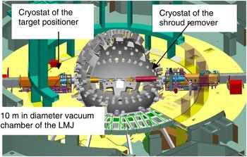
To address the stringent requirements of the operating environment in the field, as well as the robustness of the components and the biological shielding of the operators, we built a mock-up of the LMJ cryogenic infrastructure (Fig. 6). This mock-up provided validation of the design selections chosen to address the requirements. This installation, called DEMOCRYTE, includes several cryostats (the cryogenic target carrier, the system for transfer, and the shroud remover) was studied and built in 2001. It allowed testing at full-scale the first main components of the cryogenic target system. This evolving test installation will eventually contain all the systems required for the transfer of the targets, layering with infrared enhancement, and withdrawal of the thermal shroud. Using this cryostat we tested the transfer of a target arriving from Valduc. This transfer was done at 24 K then it was followed by a fine temperature control at 18 K to simulate the solidification of the DT mixture with a temperature stability of ±2 mK.
(Color online) A top view of the vacuum vessel and both cryostats.

The last step will be to test the mechanical stability during the removal of the thermal shroud. These experiments were planned at the end of 2008. This program, done step by step, shows validation of the physical concepts and tests their technological feasibility. In this manner, by relating back to the requirements for the cryogenic systems, the risks incurred by a premature choice are minimized.
DEVELOPMENT FOR HiPER
Single Shot Phase
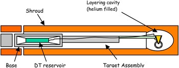
The main improvement specific to the cryosystem for HiPER is the insertion of a layering system in the front of the cryocarrier (Fig. 7). This complex system must provide a thermal uniformity with a gradient less than 75 µK around the target, and must ensure adequate heat transfer between the target and the cold source. During the single shot phase, many kinds of targets will be tested with different morphology and materials. The objective of these experiments will be to define a realistic target for an IFE reactor that can be mass produced with a low cost. In particular, during the single shot phase, physics must be studied to determine if the cone is essential for the fast ignition design. At the same time, shooting, tracking, and laser synchronization will be developed. So before the high repartition rate HiPER phase all needed systems will be tested separately.
(Color online) Upgraded front of the cryocarrier.

High Repartition Rate Phase
Definition
Prior to using tritium, HiPER will demonstrate lasers shots with a frequency close to 1 Hz. The project plan will fully integrate the experience obtained from intermediate facilities (NIF and LMJ). The laser PETAL will facilitate the route to fast turnaround and address various science and technology questions. The first step of the high repartition rate mode will be the fusion burst mode. This could be a 10 s repartition rate with N shots per burst (10 < N < 100). The goal is to define the limiting factor for survivability, target delivery, and thermal shielding.
Shooting and Tracking Target Requirements
For testing the high repartition rate mode hundreds of targets must be delivered, injected, and tracked. The road map will include separating the various issues and solving them in parallel. For this reason, during the initial burst mode very simple targets will be used. These will consist of cryogenic, empty microballoons. For these preliminary experiments, tracking and shooting must have been tested previously on a dedicated test bed. On this point, an international collaboration with experienced researchers in the USA (General Atomics) will be helpful.
Targets Mass Production
Many thousands of targets must be produced for an IFE reactor and hundreds for HiPER. Materials are a key point for the high gain target. These targets must have good mechanical properties to ensure the integrity of the target during the shot (maximum acceleration is 104 ms−2). They must be porous for the permeation filling process at room temperature and leak tight at cryogenic temperatures. The joining and bonding of materials in targets will be a key aspect, still to be fully understood, when we consider sophisticated new energy targets. For reducing the technological risk, it is very important that many kinds of targets be tested, in particular the variety of materials that are allowed owing to their activation rate. Systems associated with the microballoons (i.e., mass production, filling station, and transport systems) must be developed. Currently, the most promising route is the permeation procedure. The time required for a filling cycle is many hours. The delta P between the inner and outer walls must be lower than 100 mbar to prevent the target from bursting. For having a very low production cost, targets should be the simplest possible (no cone), and it will be easier to perform the transfer close to the experimental chamber.
Targets Layering
For smoothing the DT solid layer, we plan to use the β-layering effect. But the time constant of redistribution is around 23 min. For this reason, targets must be produced in advance and some quantity stored for an IFE reactor.
High Yield Experiments
During high gain experiments, the chamber wall must be designed to handle the required heat transfer. In addition, the issue of helium migration into the wall resulting in surface damage must be addressed. Finally, debris mitigation methods must be implemented to avoid degradation of the final optics and resulting increases in maintenance time in a nuclear environment.
CONCLUSIONS
Many technologies and test beds are now available in different laboratories and many experiments can be driven with the proposed HiPER facility (Besenbruch et al., Reference Besenbruch2000; Norimatsu et al., Reference Norimatsu2003, Reference Norimatsu2006). HiPER can be used as a pulsed neutron source, allowing neutronic experiments under prototypical conditions for IFE, and addressing key issues for a future IFE demo reactor. We essentially are pursuing two objectives (1) to obtain sufficient safety-related experimental data as required for approval and licensing of an IFE device, and (2) verification of the prediction capabilities of computational codes and their supporting database for assessment of nuclear performance of reactor components. We then will quantify the design margins and safety factors to be implemented in future IFE blanket and shield design. Target and blanket materials are key issues and HiPER experiments have to be focused on both these points.