1. Introduction
Reducing energy losses is a key goal for any type of controlled thermonuclear fusion magnetic confinement system; however, it is especially important for magnetic mirror traps, in which energy losses along magnetic field lines are an indispensable part of the system. In a number of theoretical and experimental works (Ryutov Reference Ryutov2005; Skovorodin & Beklemishev Reference Skovorodin and Beklemishev2016; Skovorodin Reference Skovorodin2019; Soldatkina et al. Reference Soldatkina, Maximov, Prikhodko, Savkin, Skovorodin, Yakovlev and Bagryansky2020) it was shown that these losses can be significantly limited, which could allow us to achieve the level of fusion power required for the implementation of projects such as a volumetric fast neutron source (Ivanov & Ryutov Reference Ivanov and Ryutov1990) or even a thermonuclear reactor (Simonen Reference Simonen2016). Currently, investigations in this field are carried out at the gas dynamic trap (GDT) facility in the Budker Institute of Nuclear Physics (Ivanov & Prikhodko Reference Ivanov and Prikhodko2013).
A number of unique results obtained at the GDT raise the importance of the energy balance problem in mirror traps. Among these results are successful hot plasma confinement with high relative pressure (which is the ratio of plasma pressure to magnetic field pressure) $\beta = 0.6$ (Simonen et al. Reference Simonen, Anikeev, Bagryansky, Beklemishev, Ivanov, Lizunov, Maximov, Prikhodko and Tsidulko2010), achievement of a fast deuterium ion density of $n_{{\rm fast}}\sim 5\times 10^{19}\,{\rm m}^{-3}$
 with an average energy of 10 keV and reaching the electron temperature of $T_e\sim 1\,{\rm keV}$
 with additional electron cyclotron resonance (ECR) plasma heating of moderate power (Bagryansky et al. Reference Bagryansky, Shalashov, Gospodchikov, Lizunov, Maximov, Prikhodko, Soldatkina, Solomakhin and Yakovlev2015). The parameters of a confined plasma in the GDT steadily approach thermonuclear values, therefore, the task of investigating total energy losses from the trap and ways to reduce them becomes more important than ever. In this study, we attempted to draw up a preliminary energy balance in the GDT by examining various energy loss channels, namely energy losses along magnetic field lines (axial losses), losses onto limiters and losses due to charge exchange and radiation in the central cell of the trap.
2. Experimental set-up
2.1. The gas dynamic trap
The layout of the GDT is shown in figure 1. The central section of the GDT is a 7 m long axisymmetric mirror cell, with a magnetic field strength of 0.36 T in the centre and up to 13 T in the plugs, intended for confinement of a two-component plasma. The first component is the warm ‘target’ plasma, confined in the gas dynamic mode with electron and ion temperatures of up to 250 eV and a density of $5\times 10^{19}$ particles per cubic metre. The second component is the fast ion population with an average energy of ${\sim }10$
 keV and density of up to $10^{19}\,{\rm m}^{-3}$
 (Ivanov et al. Reference Ivanov, Beklemishev, Kruglyakov, Bagryansky, Lizunov, Maximov, Murakhtin and Prikhodko2010). This ion population, confined adiabatically, is formed as a result of the ionisation of 8 neutral beams with an energy of 25 keV, injected obliquely into the trap, in the target plasma (Deichuli et al. Reference Deichuli, Davydenko, Ivanov, Korepanov, Mishagin, Sorokin, Stupishin and Shulzhenko2004). The fast ions slow down due to interaction with warm target plasma particles (mainly electrons), heating them to approximately 250 eV. Even higher plasma temperatures can be achieved with ECR heating, but only neutral beam heating was used in this study. Due to oblique injection and the small angular scattering of fast ions, their density turns out to be strongly peaked near the so-called turning points. This circumstance is most attractive for designing a volumetric fast neutron source as the neutrons will be radiated from a compact region.
Layout of the GDT. The locations of the diagnostics employed in this study are marked in bold.

The magnetohydrodynamic stabilisation of the warm plasma component is provided by the ‘vortex confinement’ method (Beklemishev et al. Reference Beklemishev, Bagryansky, Chaschin and Soldatkina2010), which is based on the initiation of sheared rotation of the plasma in a relatively thin peripheral layer. The plasma in this layer is in contact with special electrodes – the metal rings surrounding the plasma column called the limiters. A positive bias of 150–350 V is applied to the limiters, creating a radial electric field thus initiating sheared rotation of the peripheral plasma and saturating magnetohydrodynamic modes with small azimuthal wavenumbers. Typically, a power of approximately 50–100 kW is sufficient to generate the radial electric field appropriate for the vortex confinement.
Particle balance maintenance during work impulses was carried out by injection of molecular deuterium from the valves near the GDT mirrors. The vacuum chamber wall of the GDT was prepared using the titanium gettering method (Bagryansky et al. Reference Bagryansky, Bender, Ivanov, Karpushov, Murachtin, Noack, Krahl and Collatz1999), which allowed us to sustain the base pressure in the central cell during the shots at a level of $(0.5\unicode{x2013}1.1)\times 10^{-5}\,{\rm Pa}$ .
The main parameters of the GDT and the confined plasma are summarised in table 1.
Summary of the main parameters of the GDT.

2.2. Diagnostics
Drawing up the energy balance required us to consider which energy gain and loss channels need to be taken into account. For the energy supply into the trap, 5 MW of power were provided by neutral beam injection in each impulse, approximately one half of this power was captured by the plasma (figure 2). The captured power $P_{{\rm cap}}$ was measured by comparing readings from secondary emission detectors, located in the beam dumps, in the discharges with and without plasma, estimating the power from the currents measured and taking the difference to be the captured power.
Injected (red curve) and captured (blue curve) neutral beam injection power in a single impulse measured by secondary emission detectors located at the beam dumps.

For the energy losses, in this study we considered the following channels:
(i) Axial losses through the magnetic mirrors.
(ii) Losses due to direct contact of peripheral plasma with the radial limiters.
(iii) Ion losses caused by their charge exchange with the residual neutral gas as well as radiation losses in the central cell.
Additionally, the fast ion energy content $w_{{\rm fast}}$ was estimated from the data of the diamagnetic loop installed in the central plane of the GDT by means of the numerical code DOL (Yurov, Prikhodko & Tsidulko Reference Yurov, Prikhodko and Tsidulko2016), which is based on Coulomb scattering dynamics and allowed us to calculate the fast ion energy content as a function of time (figure 3). The rate of fast ion energy content change ${\rm d}w_{{\rm fast}}/{\rm d}t$
 was taken to be simply the time derivative of $w_{{\rm fast}}$
 .
Energy content in fast ion population reconstructed from diamagnetic loop data by the numerical code DOL (Yurov et al. Reference Yurov, Prikhodko and Tsidulko2016). Red dashed lines indicate the duration of neutral beam injection.

To measure the power flux through the mirror, we used a set of 17 pyroelectric bolometers distributed cross-wise across the absorber plate in the western expander tank of the GDT device. Each bolometer was constructed according to the design described in Soldatkina et al. (Reference Soldatkina, Maximov, Prikhodko, Savkin, Skovorodin, Yakovlev and Bagryansky2020), each detector containing a lithium niobate (LiNbO$_3$ ) crystal placed directly onto an operational amplifier. These bolometers measured the incoming power flux at multiple points on the absorber, allowing us to reconstruct the full incoming power onto the absorber $P_{{\rm absorber}}$
 by multiplying the detector reading by its assigned area section of the plate and summing up the products.
To measure power losses due to charge exchange of plasma ions with the residual gas, as well as radiation losses a set of seven pyroelectric bolometers, identical to those on the western absorber, was installed on the wall of the eastern half of the central vacuum chamber along the axis (figure 1). The bolometers measured the combined power flux from both particles and electromagnetic radiation without separating one from the other, which was acceptable for this study, as no goal was set to differentiate between the two at this time. Similarly to the absorber, the bolometers were assigned area sections of the vacuum chamber wall to multiply their measured power by; the products were then summed to obtain the total power $P_{{\rm array}}$ lost onto the eastern wall of the GDT.
The absorber bolometer set, however, only measured the axial losses into the western mirror and the central cell array only measured the charge exchange and radiation losses in the eastern half of the GDT. Therefore, to estimate the total losses through these channels we assumed that the power fluxes into the eastern mirror and western wall were (respectively) the same and doubled the measured power losses ($P_{{\rm axial}} = 2P_{{\rm absorber}}, P_{{\rm wall}} = 2P_{{\rm array}}$ ). While it might not necessarily be so, due to such factors as asymmetric neutral beam injection relative to the centre of the trap and the arc plasma gun being located in the eastern expander tank, for now, we estimate them as such to be corrected in further investigations with additional installed equipment.
To estimate the energy lost onto the limiters $E_{{\rm lim}}$ we designed thermistor-based calorimeters to be placed directly on the limiters’ front surfaces. Each calorimeter consisted of a Pt-100 thermistor mounted inside a copper box isolated electrically and thermally from the limiter itself by an insulator made of polyacetal (figure 4). The materials were chosen for the heat to spread across the copper piece evenly before any significant amount of heat is transferred to the insulator. However, the thermistor sampling rate was far too slow (${\sim }3$
 Hz) to measure the temperature dynamic during the length of the plasma discharge. Therefore, we had to estimate energy losses onto the limiter with the simple $Q = cm\Delta T({S_l}/{S_c})$
 formula, where $c$
 is the material's thermal capacity, $m$
 is the mass of the piece, $S_l$
 is the front surface area of the limiter ring and $S_c$
 is the front surface area of the copper box plus the area of one of its longer sides. Adding the latter is an attempt to roughly account for the heat from the plasma that is coming onto the side of the calorimeter due to the differential rotation of the plasma column. In our estimations we did not take into account the area of the inner surface of the limiter perpendicular to its front, assuming that the transverse power flow from the plasma is small (no more than 10 % of the axial flow, as per Bagryansky, Beklemishev & Soldatkina Reference Bagryansky, Beklemishev and Soldatkina2007); however, this will be a subject of future investigations.
Calorimeter used to measure energy losses onto the GDT limiters. (a) Cross-sectional view of the calorimeter; 1 – Pt-100 thermistor, 2 – copper box, 3 – polyacetalic insulator, 4 – limiter ring. (b) Photo of a calorimeter installed on one of the limiters.

Once the temperature jump in each discharge $\Delta T$ was measured, the energy loss was estimated accounting for both the copper box and the metal screws it is affixed to the insulator with. As such, the measurements of energy losses onto the limiter in this study were inherently restricted to integral measurements.
3. Energy balance
In this study we considered two approaches to investigating energy balance:
(i) Measuring power losses through the aforementioned channels during the impulse and observing the dynamics.
(ii) Calculating full energy losses defined by different mechanisms over the entire discharge.
3.1. Instant balance
Figure 5(a) demonstrates the estimated power dynamics in a typical GDT discharge. The power losses onto the radial limiters were not taken into account here, as the calorimeters were only able to measure the integral energy losses. The coloured lines denote the aforementioned powers according to the graph legend and the black line denotes the total accounted for power of three components $P_{\varSigma } = P_{{\rm axial}} + P_{{\rm wall}} + {\rm d}w_{{\rm fast}}/{\rm d}t$ . Of special interest is the time interval from approximately 4 to 7.4 ms, when all of the neutral beam injectors were operating and the injected power was stable. The powers of each component as percentages of $P_{{\rm cap}}$
 during this interval are plotted in figure 5(b). The figure shows that the neutral beam power that goes into the fast ion energy content ${\rm d}w_{{\rm fast}}/{\rm d}t$
 reaches its maximum of ${\sim }34\,\%$
 shortly after all the injectors start working and decreases to approximately $16\,\%$
 by the end of injection. The axial losses $P_{{\rm axial}}$
 start at their lowest of approximately $10\,\%$
 and steadily rise to ${\sim }28\,\%$
 . The ion charge exchange and radiation losses stay approximately the same at ${\sim }36\pm 2\,\%$
 throughout the injection and so does the total accounted for power $P_{\varSigma }$
 at ${\sim }80\pm 5\,\%$
 .
Instant power balance in the GDT. (a) Estimated power fluxes in and out of the confined plasma. (b) Powers of each component as percentages of $P_{{\rm cap}}$ during the interval when all neutral beam injectors are operational.

To confirm whether the axial power flux is consistent with the gas dynamic confinement regime, we compared the power measured by bolometers on the absorber with the value of the power flux through the mirror estimated theoretically based on experimental data. The power flux through the mirror in the gas dynamic regime is described by the formula

where $n$ is the plasma density, $T_e$
 is the electron temperature and $m_i$
 is the deuterium ion mass (Mirnov & Ryutov Reference Mirnov and Ryutov1988). The radial electron density and temperature profiles, obtained with Thomson scattering during a plasma discharge, are shown in figures 6(a) and 6(b), respectively, and figure 6(c) demonstrates the gas dynamic power flux, calculated with (3.1) based on these radial profiles. Figure 6(c) also shows the mean power flux values at different radii (projected along magnetic field lines into the trap centre) measured by plasma absorber bolometers at the time of Thomson scattering measurement; the standard deviations of the data are plotted as error bars. Measurements and estimations are in a quite good agreement, therefore, we can conclude that the axial power flux corresponds to gas dynamic confinement.
Radial profiles of plasma density, temperature and corresponding power flux in the central plane of the GDT obtained with the Thomson scattering system in a plasma discharge at 7.56 ms and comparison with power loss measurements from the western plasma absorber. (a) Electron density profile. (b) Electron temperature profile. (c) Gas dynamic power losses calculated using (3.1) from Thomson scattering data with mean bolometer power flux measurements projected on corresponding radii along magnetic field lines.

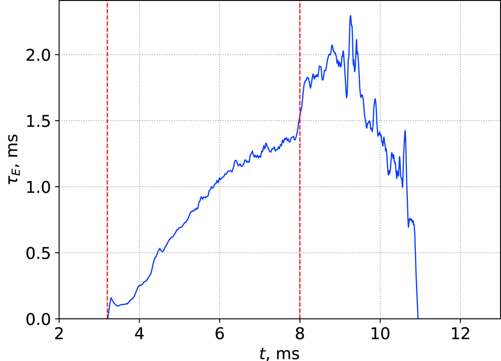
Using the obtained results on the power dynamics we estimated the instant energy lifetime (figure 7) in the GDT by dividing the energy accumulated in fast ions $w_{{\rm fast}}$ (figure 3) by the total power of losses $P_{{\rm wall}} + P_{{\rm axial}}$
 (figure 5a). The energy lifetime increases during the neutral beam injection impulse and reaches a value of approximately 1.5 ms by its end. The following sharp increase is likely associated with post-injection phase reorganisation of plasma confinement due to the increase in transverse losses which were not considered in this study and will be a subject of future investigations.

3.2. Integral balance
It is also rather interesting to consider the integral energy balance, since it is important to know whether all of the energy captured by the plasma ultimately ends up on the absorbers and structural elements of the device. For this investigation, power measurements from the diagnostics were integrated over the entire discharge duration to obtain total energy loss values.
Using the array of bolometers in the central cell, we obtained the mean axial charge exchange and radiation energy loss density profile from the plasma to get a picture of where most of the energy is lost during a plasma discharge. To obtain the typical axial energy density profile we conducted a series of experiments where plasma parameters were kept unchanged. The results, averaged over the series, are shown in figure 8, with error bars denoting the standard deviation of the data. It is worth noting that the peak energy density is registered by the bolometer located at 180 cm from the centre of the trap. This result was expected, since this point roughly corresponds to the coordinate of the fast ions’ turning point of 190 cm (in the standard magnetic configuration of the GDT, which was used in these experiments).
Mean energy density along the GDT axis calculated over a series of discharges with constant plasma parameters. The red dashed line marks the fast ions’ turning point.

Next, a series of experiments was conducted to estimate which fraction of the energy captured by plasma is lost via the indicated channels. In this series, the number of operating neutral beam injectors was changed in order to vary the energy captured by the plasma and obtain the dependency of the lost energy on the captured energy. The results are presented on figure 9.
Energy losses on the elements of the GDT: blue – radial limiters, green – western absorber, red – eastern vacuum chamber wall.

The measured data from each diagnostic were fitted with a straight line using the least squares method, which allowed us to estimate the contribution of each loss channel to the integral energy balance. Approximately 16 % of the captured energy was lost onto the western absorber of the GDT. Assuming again that the same amount of power is lost to the eastern mirror as well, we estimated that the axial losses in the GDT constituted 32 % of the captured energy.
The wall losses in the respective series constituted 20 % of captured energy. Once again, assuming that energy fluxes onto both halves of the central cell are symmetrical relative to the centre of the trap, we conclude that approximately 40 % of the captured power was lost via charge exchange and radiation. It should also be noted that this value is a lower-bound estimate, since some areas were not covered by bolometers and energy fluxes onto the wall in these areas were not measured.
Finally, the energy losses onto the radial limiters of the GDT constituted approximately 9 % of the energy captured by plasma, bringing the total estimated energy losses to 81 %.
4. Conclusion
In this study we conducted a series of experiments to measure the power and energy losses from a plasma confined in a GDT.
The instant energy balance investigation demonstrated that, during the neutral beam injection, approximately 16 %–34 % of the power captured from the neutral beams went into confined plasma's fast ion energy content, and 10 %–28 % was lost axially (the fractions varied during the discharge). The axial power loss values were consistent with gas dynamic confinement. The charge exchange and radiation losses stayed relatively constant during the discharge and constituted approximately $36\pm 2\,\%$ of the captured power. In total, these measurements accounted for ${\sim }80\pm 5\,\%$
 of the captured power during neutral beam injection. Instant power losses onto the radial limiters were not considered in this balance due to the integral character of the calorimeters placed on the limiters.
To draw up an integral energy balance, we varied the energy captured by the plasma from neutral beam injection and measured the total energy losses onto the western plasma absorber, the eastern half of the central cell's wall and the radial limiters. Based on these experiments, we estimate that 32 % of the captured energy was lost through the magnetic mirrors, 9 % was lost on the limiters and 40 % was lost due to ions exchanging charge with residual neutral gas and radiation. This in total accounts for approximately 81 % of captured energy losses. The missing 19 % was most likely lost to charge exchange and radiation in areas unequipped with bolometers.
From both types of energy balance investigations it is obvious that the value of the energy lost to charge exchange and radiation is rather high and should be reduced. Although it is yet to be verified experimentally, we assume that it is the fast ion charge exchange on the residual gas that is dominant in this loss channel. In the near future we plan to conduct a series of experiments where, instead of gas puffing, the plasma material balance is maintained with the injection of an accelerated plasma jet from a special Marshall-type gun (Marshall Reference Marshall1960), which is currently being developed in our laboratory. This method of maintaining the particle balance could possibly reduce the charge exchange losses, increase the efficiency of plasma heating and improve its confinement in the GDT.
Acknowledgements
The authors are grateful to Dr A.A. Lizunov for providing Thomson scattering diagnostic data, to Dr V.V. Prikhodko for DOL code calculations and to technicians A.I. Sizikov, A.V. Tur and I.Y. Zakharenko for the technical support during the experiment.
Editor C. Forest thanks the referees for their advice in evaluating this article.
Funding
The study was supported by the Ministry of Science and Higher Education of the Russian Federation.
Declaration of interests
The authors report no conflict of interest.