NOMENCLATURE
- I x, I y, I z =
roll, pitch and yaw moments of inertial, kg · m 2
- l =
distance between mass point of Nano quad-rotor and rotor, m
- m =
mass of Nano quad-rotor, Kg
- g =
gravitational constant, m/s 2
- g 1, g 2, g 3 =
unknown non-linear terms, rad/s 2
- p, q, r =
roll, pitch, and yaw rate, rad/s
- T r=
thrust of rotors, N
- υ x, υ y, υ z =
velocity of Nano quad-rotor in inertial coordinate, m/s
- w x, w y, w z =
wind velocity in inertial coordinate, m/s
- x, y, z =
position of mass point of Nano quad-rotor in inertial coordinate, m
- x d, y d, z d =
reference path, m
- Δf p, Δf q, Δf r =
unmodeled dynamics, rad/s 2
- Δf x, Δf y, Δf z =
unmodeled dynamics, m/s 2
- ϕ, θ, ψ =
roll, pitch, and yaw angles, rad
- τ 1, τ 2, τ 3 =
roll, pitch, and yaw moments, Nm
- Φp, Φq, Φr =
pseudo gradients for body rate control
- Φυ x, Φυ y, Φυ z =
pseudo gradients for velocity control
- Φx, Φy, Φz =
pseudo gradients for position control
1.0 INTRODUCTION
In the past two decades, the dynamic inversion (DI) method has been widely applied in the field of quad-rotor control(Reference Lin, Cai, Wang, Yang and Chen1,Reference Das, Subbarao and Lewis2) . Compared with conventional methods such as Proportional-Integral-Derivative (PID)(Reference Sá, Araújo, Varela and Barreto3), linear quadratic regulator (LQR)(Reference Bouabdallah, Noth and Siegwart4), robust control(Reference Islam, Faraz, Ashour, Dias and Seneviratne5), sliding mode control(Reference Fan, Cao and Zhao6) and back-stepping control(Reference Madani and Benallegue7), it is simple in control scheme and easy in parameter tuning; however, it demands an accurate model of aircraft, which is its largest flaw and the reason for its poor robustness(Reference Schumacher and Khargonekar8). Nano quad-rotors have a low in-flight speed, and are light in weight and limited in thrust; thus, they are susceptible to external disturbances (such as from wind field) and internal disturbances (such as unmodeled dynamics and perturbation of measurable parameters). Therefore, it is difficult, or even impossible, to obtain their accurate model, resulting in poor body stability and flight performance. Targeting the flight of quad-rotors (including regular-sized and Nano-sized) in a wind field and under parameter perturbations, many studies have been carried out. For example, the active disturbance rejection control (ADRC), which uses extended state observer (a DO) to observe disturbances that can be modelled, was used in the design of attitude system control(Reference Ye, Lan, Jin and Huang9,Reference Libo, Wenya and Wenhui10) but it shows deficiency in estimation of disturbances that cannot be modelled(Reference Beard and Mclain11), such as a turbulent wind field. In addition, parameter tuning of ADRC-based controllers are not convenient. For another example, robust control is used to deal with small disturbances encountered by quad-rotors in flight(Reference Islam, Faraz, Ashour, Dias and Seneviratne5), but research on the Nano quad-rotors in flight under disturbances is quite limited.
It can be seen from the above analysis that a good flight controller should have good performance in dealing with internal and external disturbances; therefore, a disturbance observer (DO) is adopted to enhance the conventional DI method and improve the system robustness of Nano quad-rotors. First, a novel data-based DO, which can only use rough model information to estimate disturbances (including internal and external disturbances and non-linear terms affecting model accuracy) of control system, is proposed to eliminate the accurate model dependency of the conventional DI method and significantly improve system robustness of the DI method. Secondly, the stability of the DO proposed is verified. Finally, the proposed DO is integrated into the conventional DI method to replace the accurately modelled terms with disturbance terms observed by the DO for design of control scheme. Simulation results show that the EDI method, which does not rely on an accurate model of the quad-rotors, realises good performance in tracking a given path under a wind field. It is demonstrated that the proposed DO can accurately estimate both disturbances that cannot be modelled, such as a wind field and disturbances that can be modelled due to error in parameter estimation.
2.0 MODEL OF NANO QUAD-ROTORS SUBJECT TO DISTURBANCES
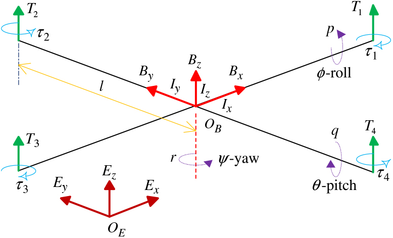
Two main coordinates, some forces, moments and geometrical parameters are introduced first before modelling Nano quad-rotors, as shown in Fig. 1,
Preliminary knowledge of quad-rotors.

In Fig. 1, O EE xE yE z represents the inertial coordinate, in which E x and E y are on the horizontal plane and E x is perpendicular to E y, and E z is perpendicular to the horizontal determined by right-hand rule. O BB xB yB z represents the body coordinate whose origin is fixed at the centre of gravity of the quad-rotor. B x is the normal flight orientation, B y is positive to starboard in the horizontal plane and B z is orthogonal to the plane B xO BB y.
The non-linear equations of motion subject to disturbances for Nano quad-rotors(Reference Derafa, Ouldali and Benallegue12) are expressed as:
 $$\begin{equation}
\left\{\begin{array}{l} {\mathop{x}\limits^{\bullet } =v_{x} +w_{x} } \\[1.5pt] {\mathop{y}\limits^{\bullet } =v_{y} +w_{y} } \\[1.5pt] {\mathop{z}\limits^{\bullet } =v_{z} +w_{z} } \end{array}\right. ,\; \; \; \left\{\begin{array}{l} {\mathop{v_{x} }\limits^{\bullet } =(\cos \phi \sin \theta \cos \psi +\sin \phi \sin \psi )\frac{T_{r} }{m} +\Delta f_{x} } \\[1.5pt] {\mathop{v_{y} }\limits^{\bullet } =(\cos \phi \sin \theta \sin \psi -\sin \phi \cos \psi )\frac{T_{r} }{m} +\Delta f_{y} } \\[3pt] {\mathop{v_{z} }\limits^{\bullet } =-g+\frac{T_{r} }{m} \cos \phi \cos \theta +\Delta f_{z} } \end{array}\right. ,\\
\left\{\begin{array}{l} {\mathop{\phi }\limits^{\bullet } =p+q\sin \phi \tan \theta +r\cos \phi \tan \theta } \\ {\mathop{\theta }\limits^{\bullet } =q\cos \phi -r\sin \phi } \\ {\mathop{\psi }\limits^{\bullet } =q\sin \phi \sec \theta +r\cos \phi \sec \theta } \end{array}\right. , \left\{\begin{array}{l} {\mathop{p}\limits^{\bullet } =\underbrace{\frac{I_{y} -I_{z} }{I_{x} } qr+\Delta f_{p} +\left(\frac{l}{I_{x} } -b_{1} \right)\tau _{1} }_{g_{1} (p,q,r;t)}+b_{1} u_{1} } \\ {\mathop{q}\limits^{\bullet } =\underbrace{\frac{I_{z} -I_{x} }{I_{y} } pr+\Delta f_{q} +\left(\frac{l}{I_{y} } -b_{2} \right)\tau _{2} }_{g_{2} (p,q,r;t)}+b_{2} u_{2} } \\ {\mathop{r}\limits^{\bullet } =\underbrace{\frac{I_{x} -I_{y} }{I_{z} } pq+\Delta f_{r} +\left(\frac{1}{I_{z} } -b_{3} \right)\tau _{3} }_{g_{3} (p,q,r;t)}+b_{3} u_{3} } \end{array}\right.
\end{equation}$$
Equation (1) is formed by four equation sets in which the first set represents translational kinematics (position control), the second set represents translational dynamics (velocity control), the third set represents rotational kinematics (Euler angle control) and the fourth set represents rotational dynamics (body rate control). In the above, [x, y, z]T and [υ x, υ y, υ z]T ∈ R 3 represent position and velocity vectors in inertial frame, respectively. m and g represent mass and gravitational constant, respectively. [ p, q, r]T ∈ R 3 is the angular velocity vector under body coordinate system. [ϕ, θ, ψ]T ∈ R 3 is the Euler angle under inertial coordinate system. T r is lift and [u 2, u 3, u 4]T represents virtual inputs (roll force, pitch force and yaw moment) acting on quad-rotors. I x, I y, I z are moments of inertial. w x, w y and w z represent wind velocity in inertial frame along the x, y and z axes, respectively. Δf x, Δf y, Δf z, Δf p, Δf q and Δf r are unmodeled dynamics. b 1, b 2 and b 3 are estimations of l/I x , l/I y and 1/I z, respectively.
3.0 DISTURBANCE OBSERVER DESIGN FOR AN AFFINE NON-LINEAR SYSTEM
3.1 Design procedure
Consider the commonly used first-order affine non-linear system with disturbance, shown as:
 $$\Sigma _1 :\;\;\mathop y\limits^ \bullet {\kern 1pt} = \;f(y,t) + b(y,t) \cdot u(t) + d(t)
$$
where, f (∗) and b(∗) are unknown, and d(t) includes internal and external disturbances. u(t) and y are measurable variables, representing input and output, respectively.
A discretising system Σ1 with the sampling time period T yields:
 $$\
y(k + 1) = y(k) + T \cdot \left[ {f(y(k),t(k)) + b(y(k),t(k)) \cdot u(k) + d(t(k))} \right]
$$
Select a reference model with a discretised formation as:
 $$\
y_m (k + 1) = y_m (k) + T \cdot b_m \cdot u(k)
$$
where, the gain b m is given. The rest of the work is to estimate g( y(k), u(k); t(k))=f ( y(k), t(k))+ (b( y(k), t(k)) − b m)u(k) + d(t(k)) by designing a DO using input and output data.
Taking the notation e(k) = y(k) − y m (k) and subtracting Equation (4) from (3) yields a new non-linear system:
 $$\Sigma _2 :\;\;\Delta e(k + 1) = T \cdot g(y(k),u(k);t(k))
$$
Then at k th sampling time point:
 $$\Delta e(k) = T \cdot g(y(k - 1),u(k - 1);t(k - 1))
$$
Subtracting Equation (6) from (5) yields:
 $$\Delta e(k + 1) = \Delta e(k) + \Delta g(y(k),u(k);t(k))
$$
Reference(Reference Hou, Chi and Gao13) introduces a non-linear discrete system written as:
 $$\Sigma _0 :\;\;y(k + 1) = f(y(k), \cdots ,y(k - n_y ),u(k), \cdots ,u(k - n_u ))
$$
can be linearized into the following formation by using dynamic linearization (DL) theory:
 $$\Delta y(k + 1) = \Phi ^T (k)\Delta H(k)
$$
where, u(k) ∈ R and y(k) ∈ R represent input and output of the system, respectively. n y and n u are two integers.  $f(*):\; R^{n_{y} +n_{u} +2} \mapsto R$ is a non-linear mapping.
 $\Phi (k)=[\phi _{1} (k),\cdots\phi _{L_{y} } (k),\phi _{L_{y} +1} (k),\cdots ,\phi _{L_{y} +L_{u} } (k)]^{T} \in R^{L_{y} +L_{u} } $ is a time-varying vector called pseudo gradient (PG), and ||Φ(k)|| ≤ b, L y and L u(0 ≤ L y ≤ n y, 1 ≤ L u ≤ n u) are integers called pseudo order (PO). Δy(k) = y(k) − y(k − 1), Δu(k) = u(k) − u(k − 1) and ΔH(k) = H(k) − H(k − 1) = [Δy(k)· · · Δy(k − L y + 1), Δu(k), · · · Δu(k − L u + 1)]T.
Applying DL theory to a linearize system Σ2 yields:
 $$\Sigma _2 :\;\;\Delta e(k + 1) = \Delta e(k) + T \cdot \Phi (k) \cdot \Delta H(k)$$
where, ΔH(k) =[Δ e(k),· · · Δ e(k − L y + 1), Δ u(k), · · · Δu(k − L u + 1)]T.
Thus, finally, by making a comparison with Equation (7) and (10), the disturbance term can be estimated as:
 $$\
g(y(k),u(k);t(k)) = \frac{{\Delta e(k)}}{T} + \Phi (k) \cdot \Delta H(k)
$$
It can be seen that only Φ(k) needs to be updated online. By using the following cost function:
 $$\
J(\underline \Phi (k)) = \left| {y(k) - y(k - 1) - \underline \Phi ^T (k)\Delta H(k - 1)} \right|^2 + \mu \left\| {\underline \Phi (k) - \underline \Phi (k - 1)} \right\|^2
$$
and letting  $\frac{{\partial J(\underline \Phi (k))}}{{\partial \underline \Phi (k)}} = 0$ , the PG
 $\underline \Phi (k)$ can be updated online as:
 $$\underline \Phi (k) = \underline \Phi (k - 1) + \frac{{\gamma \Delta H(k)\left[ {y(k) - y(k - 1) - \underline \Phi ^T (k - 1)\Delta H(k - 1)} \right]}}{{\mu + \left\| {\Delta H(k - 1)} \right\|^2 }}
$$
where, γ ∈ (0, 2], μ > 0 and  $\underline \Phi (k)$ is the estimation of Φ(k) In the next section,
 $\underline \Xi $ represents the estimation of Ξ .
3.2 Convergence analysis
This part aims to prove the boundedness of the error between Φ(k) and  $\underline \Phi (k)$. Subtracting the real value Φ(k) from both sides of Equation (13) and denoting
 $\underline {\underline \Phi } (k) = \underline \Phi (k) - \Phi (k)$ yields:
 $$\underline {\underline \Phi } (k) = \left[ {I - \frac{{\gamma \cdot \Delta H(k - 1) \cdot \Delta H^T (k - 1)}}{{\mu + \left\| {\Delta H(k - 1)} \right\|^2 }}} \right]\underline {\underline \Phi } (k - 1) + \Phi (k - 1) - \Phi (k)
$$
where, I is an identity matrix.
Taking the norm of both sides of Equation (14) yields:
 \begin{align}\label{GrindEQ_15}
\left\| \underline{\underline{\Phi }} (k)\right\| & \le \left\| \left[I-\dfrac{\gamma \cdot \Delta H(k-1)\cdot \Delta H^{T} (k-1)}{\mu +\left\| \Delta H(k-1)\right\| ^{2} } \right]\underline{\underline{\Phi }} (k-1)\right\| +\left\| \Phi (k-1)-\Phi (k)\right\| \nonumber\\[3pt]
& \le \left\| \left[I-\dfrac{\gamma \cdot \Delta H(k-1)\cdot \Delta H^{T} (k-1)}{\mu +\left\| \Delta H(k-1)\right\| ^{2} } \right]\underline{\underline{\Phi }} (k-1)\right\| +2b \end{align}
Since
 \begin{align}\label{GrindEQ_16}
& \left\| \left[I-\frac{\gamma \cdot \Delta H(k-1)\cdot \Delta H^{T} (k-1)}{\mu +\left\| \Delta H(k-1)\right\| ^{2} } \right]\underline{\underline{\Phi }} (k-1)\right\| ^{2} \le \left\| \underline{\underline{\Phi }} (k-1)\right\| ^{2}\nonumber\\[3pt]
& \quad +\left[-2+\frac{\gamma \cdot \left\| \Delta H(k-1)\right\| ^{2} }{\mu +\left\| \Delta H(k-1)\right\| ^{2} } \right]\cdot \frac{\gamma \left[\underline{\underline{\Phi }} ^{T} (k-1)\Delta H(k-1)\right]^{2} }{\mu +\left\| \Delta H(k-1)\right\| ^{2} }
\end{align}
Based on γ ∈ (0, 2] and μ > 0, the following inequality works:
 $$\
- 2 + \frac{{\gamma \cdot \left\| {\Delta H(k - 1)} \right\|^2 }}{{\mu + \left\| {\Delta H(k - 1)} \right\|^2 }} \lt 0
$$
Thus:
 $$\left\| {\left[ {I - \frac{{\gamma \cdot \Delta H(k - 1) \cdot \Delta H^T (k - 1)}}{{\mu + \left\| {\Delta H(k - 1)} \right\|^2 }}} \right]\underline {\underline \Phi } (k - 1)} \right\| \le \xi \left\| {\underline {\underline \Phi } (k - 1)} \right\|
$$
where, 0 < ξ < 1. Finally, the following relationship works:
 \begin{align}\label{GrindEQ_19}
& \left\| \underline{\underline{\Phi }} (k)\right\| \le \xi \left\| \underline{\underline{\Phi }} (k-1)\right\| +2b\le \xi ^{2} \left\| \underline{\underline{\Phi }} (k-2)\right\| \nonumber\\[4pt] & \qquad +{} 2\xi b+2b\le \cdots \le \xi ^{k-1} \left\| \underline{\underline{\Phi }} (1)\right\| +\frac{2b(1-\xi ^{k-1} )}{1-\xi }
\end{align}
Thus, error convergence of the proposed DO is proved.
4.0 CONTROL SCHEME
Since all states in a Nano quad-rotor system are observable and measurable, the reference model can be selected as:
 \begin{equation}
\left\{\begin{array}{l} {\mathop{x_{m} }\limits^{\bullet } =v_{xm} } \\[2pt] {\mathop{v_{xm} }\limits^{\bullet } =\underbrace{(\cos \phi \sin \theta \cos \psi +\sin \phi \sin \psi )\frac{T_{r} }{m} }_{\xi _{x} }} \end{array}\right. \!,\; \; \left\{\begin{array}{l} {\mathop{y_{m} }\limits^{\bullet } =v_{ym} } \\[2pt] {\mathop{v_{ym} }\limits^{\bullet } =\underbrace{(\cos \phi \sin \theta \sin \psi -\sin \phi \cos \psi )\frac{T_{r} }{m} }_{\xi _{y} }} \end{array}\right.\! ,\nonumber\end{equation} \begin{equation}\label{GrindEQ_20}\left\{\begin{array}{l} {\mathop{z_{m} }\limits^{\bullet } =v_{zm} } \\[2pt] {\mathop{v_{zm} }\limits^{\bullet } =\underbrace{-g+\frac{T_{r} }{m} \cos \phi \cos \theta }_{\xi _{z} }} \end{array}\right. ,\; \; \left\{\begin{array}{l} {\mathop{p_{m} }\limits^{\bullet } =b_{1} u_{2} } \\[2pt] {\mathop{q_{m} }\limits^{\bullet } =b_{2} u_{3} } \\[3pt] {\mathop{r_{m} }\limits^{\bullet } =b_{3} u_{4} } \end{array}\right.
\end{equation}
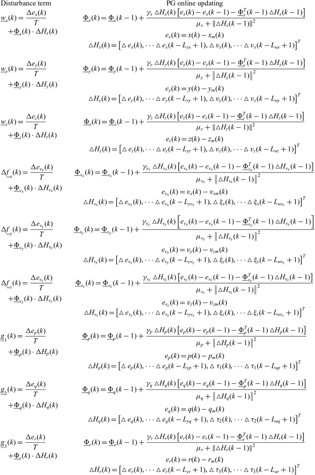
Thus, the wind velocities and unmodeled dynamics can be observed using the DO proposed as shown in Table 1:
Disturbance observers design for Nano quad-rotor control system

Based on the estimations of disturbances, the position control scheme is:
 $$\
x\;control:\left\{ {\begin{array}{*{20}c}
{\mathop x\limits^ \bullet _c = \omega _1 (x_c - x)} \hfill \\
{v_{xc} = \mathop x\limits^ \bullet _c - \underline w _x } \hfill \\
{\mathop {v_{xc} }\limits^ \bullet = \omega _2 (v_{xc} - v_x )} \hfill \\
{\xi _x = \mathop {v_{xc} }\limits^ \bullet - \Delta \underline f _x } \hfill \\
\end{array}} \right.,\;\;\;y\;control:\left\{ {\begin{array}{*{20}c}
{\mathop y\limits^ \bullet _c = \omega _1 (y_c - y)} \hfill \\
{v_{yc} = \mathop y\limits^ \bullet _c - \underline w _y } \hfill \\
{\mathop {v_{yc} }\limits^ \bullet = \omega _2 (v_{yc} - v_y )} \hfill \\
{\xi _y = \mathop {v_{yc} }\limits^ \bullet - \Delta \underline f _y } \hfill \\
\end{array}} \right.,\;\;\;z\;control:\left\{ {\begin{array}{*{20}c}
{\mathop z\limits^ \bullet _c = \omega _1 (z_c - z)} \hfill \\
{v_{zc} = \mathop z\limits^ \bullet _c - \underline w _z } \hfill \\
{\mathop {v_{zc} }\limits^ \bullet = \omega _2 (v_{zc} - v_z )} \hfill \\
{\xi _z = \mathop {v_{zc} }\limits^ \bullet - \Delta \underline f _z } \hfill \\
\end{array}} \right.$$
where, x c, y c and z c represent the reference path. υ xc, υ yc and υ zc are command translational velocity. ω 1 and ω 2 are controller parameters. By commanding the desired yaw angle, the desired Euler angle and thrust can be solved by following equations:
 $$\left\{ {\begin{array}{*{20}c}
{\psi _c = Commanded\;\;\;value} \hfill \\
{\phi _c = \arcsin \left( {\frac{{\xi _x \sin \psi _c - \xi _y \cos \psi _c }}{{\sqrt {\xi _x^2 + \xi _y^2 + (\xi _z + g)^2 } }}} \right)} \hfill \\
{\theta _c = \arctan \left( {\frac{{\xi _x \cos \psi _c + \xi _y \sin \psi _c }}{{\xi _z + g}}} \right)} \hfill \\
{T_r = m[\xi _x \left( {\cos \phi _c \sin \theta _c \cos \psi _c + \sin \phi _c \sin \psi _c } \right)} \hfill \\
{\quad \quad + \xi _y (\cos \phi _c \sin \theta _c \sin \psi _c - \sin \phi _c \cos \psi _c ) + (\xi _z + g)\cos \phi _c \cos \theta _c ]} \hfill \\
\end{array}} \right.$$
and the attitude control scheme is:
 $$\
Roll\;rate:\left\{ {\begin{array}{*{20}c}
{p_c = \omega _3 (\phi _c - \phi )} \hfill \\
{\mathop {p_c }\limits^ \bullet = \omega _4 (p_c - p)} \hfill \\
{u_2 = \frac{1}{{b_1 }}(\mathop {p_c }\limits^ \bullet - \underline g _1 )} \hfill \\
\end{array}} \right.,\;\;\;Pitch\;rate:\;\left\{ {\begin{array}{*{20}c}
{q_c = \omega _3 (\theta _c - \theta )} \hfill \\
{\mathop {q_c }\limits^ \bullet = \omega _4 (q_c - q)} \hfill \\
{u_3 = \frac{1}{{b_2 }}(\mathop {q_c }\limits^ \bullet - \underline g _2 )} \hfill \\
\end{array}} \right.,\;\;\;\;Yaw\;rate:\left\{ {\begin{array}{*{20}c}
{r_c = \omega _3 (\psi _c - \psi )} \hfill \\
{\mathop {r_c }\limits^ \bullet = \omega _4 (r_c - r)} \hfill \\
{u_4 = \frac{1}{{b_3 }}(\mathop {r_c }\limits^ \bullet - \underline g _3 )} \hfill \\
\end{array}} \right.$$
In above equation, ϕ c, θ c and ψ c are command Euler angle. p c, q c and r c are command body rate. ω 3 and ω 4 are controller parameters.
5.0 NUMERICAL VALIDATION
In this part, a numerical simulation was conducted to verify the proposed control scheme. The parameters(Reference Li and Chen14) of the Nano quad-rotor used here are: m = 0.04389kg, l = 0.035m, I x = I y = 1.916 × 10⁻⁵ and I z = 2.781 × 10⁻⁵.
The Dryden model(Reference Beard and Mclain11) is adopted to generate the wind field in which the steady wind velocities along the x, y and z axes in the earth frame are assumed to be 1 m/s. To show that the path following the Nano quad-rotor does not depend on the detailed model information, we assume that the three parameters b 1, b 2 and b 3 perturb within a wide area, in order to show that the Nano quad-rotor does not depend on the detailed model information when it does path following task −30% ~ +0.5m. Meanwhile, an additional mass with the weight 50%m is added on the Nano quad-rotor.
The parameters in above scheme are:
ω 1 = 2, ω 2 = 4, ω 3 = 6 and ω 4 = 30. The relationships ω 4 = n 1ω 3, ω 2 = n 2ω 1, n i = 2 ~ 5, i = 1, 2 work according to the response speed (body rate p, q, r > Euler angle ϕ, θ, ψ > translational velocity υ x, υ y, υ z > position x, y, z) of the quad-rotor system.
γ x= γ y = γ z = 1, γ υx = γ υy = γ υz = 1, γ p = γ q = γ r = 1, μ x = μ y = μ z = 1, μ υx = μ υy = μ υz = 1 and μ p = μ q = μ r = 1. They satisfy the conditions γ ∈ (0, 2] and μ > 0 mentioned in Section 3.2.
L yx = L yy = L yz = 0, L yυx = L yυy = L yυz = 0, L yp = L yq = L yr = 0, L ux = L uy = L uz = 1, L uυx = L uυy = L uυz = 1 and L up = L uq = L ur = 1. These parameters control the linearized length of the quad-rotor system. Other values are also applicable.
The reference signal is:
 $$\
x_c (t) = \frac{1}{2}\cos t\;\;(m),\;\;y_c (t) = \frac{1}{2}\sin t\;\;(m),\;\;z_c (t) = - 1 - \frac{t}{{10}}\;\;(m),\;\;\psi _c (t) = \frac{\pi }{3}\;\;(rad)
$$
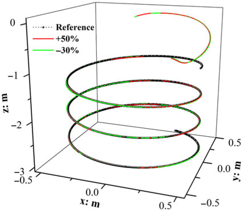
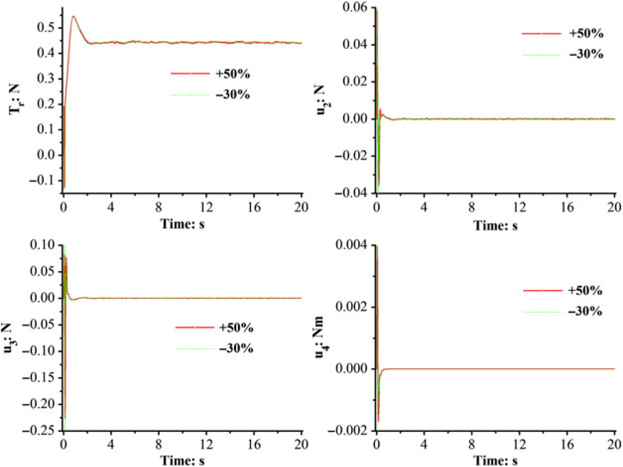
Simulation results are shown as in Fig. 2–Fig. 9:
Effect of 3D path following.

Virtual inputs.

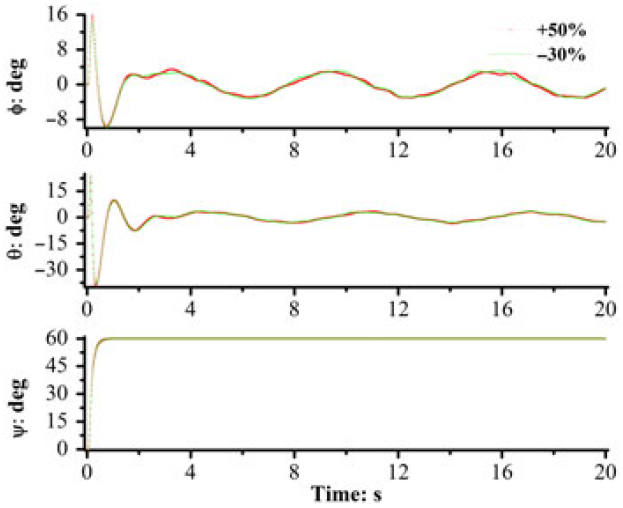
Euler angle.

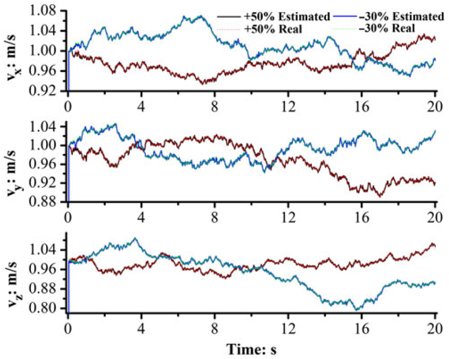
Estimation of w x, w y and w z.

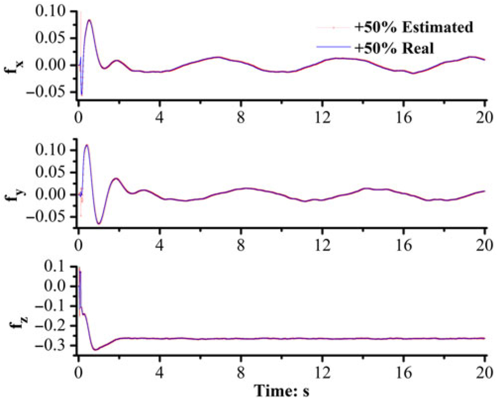
Estimation of f x, f y and f z: +50% perturbation.

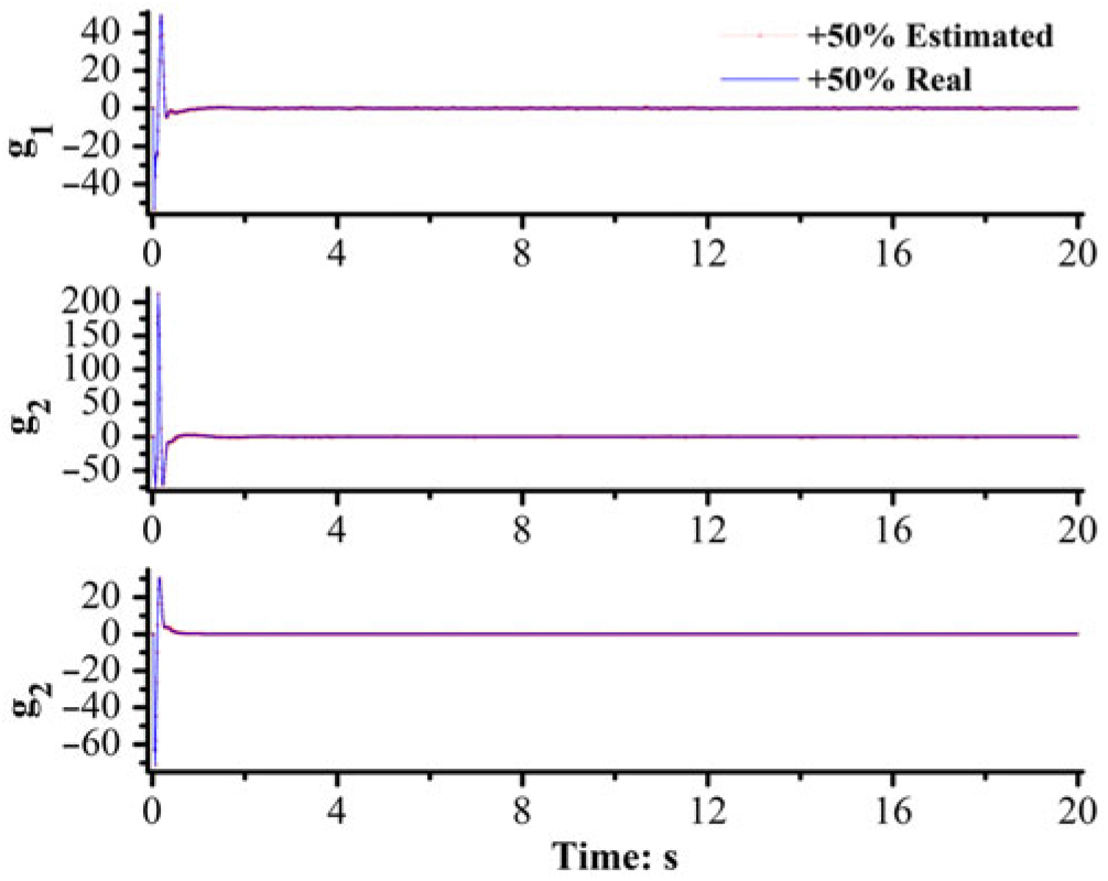
Estimation of g 1, g 2 and g 3: +50% perturbation.

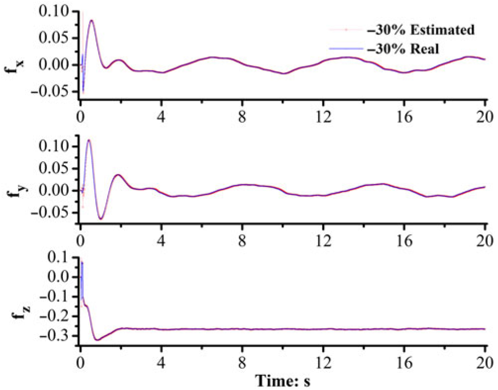
Estimation of f x, f y and f z: −30% perturbation.

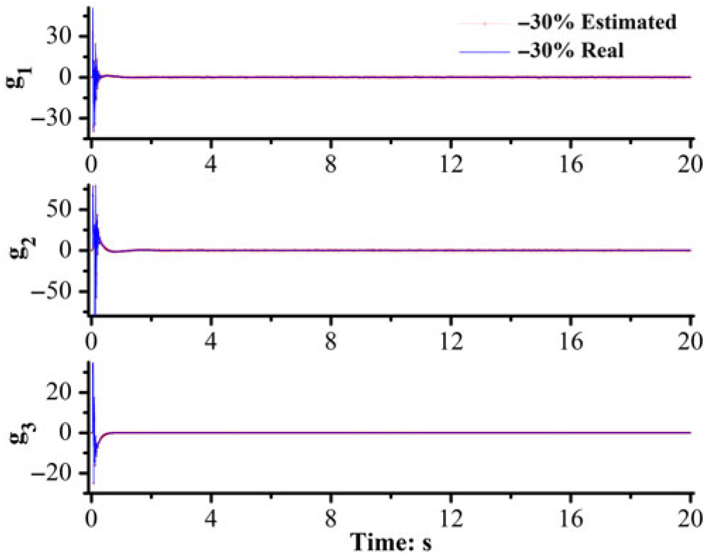
Estimation of g 1, g 2 and g 3: −30% perturbation.

It is clearly shown in Fig. 2–Fig. 4 that the EDI-based method achieves good performance under the wind field without using an accurate model, bringing a satisfactory response time. In Figs. 5–9, the proposed DO accurately estimates not only the disturbances that can be modelled, but also the coloured noise. In the Dryden wind field model, the wind is actually the steady wind adding turbulence (simulated using coloured noise converted from a standard Gaussian white noise signal passing through forming filter); thus, in fact, the disturbance is not time continuous. Since the disturbance estimation in the DO proposed in this paper is based on the differences between plant model and reference model, the characteristics of the disturbance are not strictly assumed.
6.0 CONCLUSIONS
An EDI method that eliminates detailed model dependency, which is the largest flaw of conventional DI method, is proposed for trajectory tracking and control of Nano quad-rotors. Firstly, for a measurable and observable system, a novel data-based DO is proposed to estimate both disturbances that cannot be modelled, such as a wind field and disturbances that can be modelled due to error in parameter estimation. Secondly, the stability of the proposed DO is verified. Finally, the proposed DO is adopted to enhance the DI method for better robustness. Simulation results show that, even with the relatively large error in the estimation of model parameters and under disturbances from a wind field, the enhanced DI method can realise trajectory tracking and control of Nano quad-rotors.
ACKNOWLEDGEMENTS
This publication was supported by the Priority Academic Program Development of Jiangsu Higher Education Institutions.