


Introduction
Significant effort has been directed at the development of functional nanomaterials for state-of-the-art device components, such as transistors,Reference Sekitani, Zschieschang, Klauk and Someya1–Reference Kim, Lai, Diroll, Murray and Kagan4 memory,Reference Liu, Liu, Zhu, Yu, He, Leow, Wang, Chandran, Qi, Wang, Chen, Xu and Chen5–Reference Lee, Yoo, Lee, Cha, Lee, Cho, Kim, Seo, Lee, Son, Kang, Kim, Park, Hyeon and Kim7 light-emitting devices,Reference Choi, Yang, Kang, Kim, Choi, Park, Kim, Chae, Kim, Kim, Hyeon and Kim8–Reference Kim, Shim, Yang, Choi, Kim, Kim, Hyeon and Kim12 sensors and actuators,Reference Park, Kim, Lee, Lee and Ko13–Reference Pan, Liu, Shi, Shang, Leow, Liu, Jiang, Li, Chen and Li16 and electrochemical energy devices,Reference Jung, Hong, Kim, Lee, Hyeon, Lee and Kim17–Reference Ha, Park, Lee and Ko21 to overcome the performance limitations imposed by the use of conventional materials. Additionally, the fabrication of multifunctional flexibleReference Kaltenbrunner, Sekitani, Reeder, Yokota, Kuribara, Tokuhara, Drack, Schwodiauer, Graz, Bauer-Gogonea, Bauer and Someya22–Reference Liu, Yu, Yan, Li and Zheng26 and stretchableReference Kim, Lu, Huang and Rogers27–Reference Yu, Yeo, Soon, Yeo, Lee and Lim32 electronic systems via the integration of such nanomaterial-based deformable device componentsReference Yeo, Kim, Lee, Ameen, Shi, Li, Wang, Ma, Jin, Kang, Huang and Rogers33–Reference Lee, Kim, Koo, Kim and Kim35 has also attracted substantial attention. The functionalization of nanomaterials to improve biocompatibility has allowed for safe biomedical applications of these soft integrated electronic systems. These research efforts have significantly facilitated overall technological development of wearable and implantable bioelectronics.Reference Choi, Park, Choi, Qiao, Ghaffari, Kim, Lee, Kim, Hyun, Kim, Hwang, Kwon, Hyeon, Lu and Kim36–Reference Hong, Jeong, Cho, Lu and Kim39 Yet, many challenges remain for the widespread utilization of nanomaterials-based flexible and stretchable devices and their integration into systems for wearableReference Gao, Emaminejad, Nyein, Challa, Chen, Peck, Fahad, Ota, Shiraki, Kiriya, Lien, Brooks, Davis and Javey40–Reference Yokota, Zalar, Kaltenbrunner, Jinno, Matsuhisa, Kitanosako, Tachibana, Yukita, Koizumi and Someya44 and implantableReference Park, Brenner, Shin, Morgan, Copits, Chung, Pullen, Noh, Davidson, Oh, Yoon, Jang, Samineni, Norman, Grajales-Reyes, Vogt, Sundaram, Wilson, Ha, Xu, Pan, Kim, Huang, Montana, Golden, Bruchas, Gereau and Rogers45–Reference Choi, Lee, Cho, Koo and Kim49 bioelectronics applications.
Recently, various research groups capable of synthesizing nanomaterials with diverse sizes/dimensions or functionalizing their surfaces to suit specific biomedical application conditions have relentlessly pursued high standards to improve the potential of nanomaterials-based bioelectronics up to the level of practical clinical applications.Reference Choi, Lee, Ghaffari, Hyeon and Kim50–Reference Wang, Yang, Tang, Zhao, Tong and Liu53 For example, carbon-nanomaterials-based electrodesReference Lee, Choi, Lee, Cho, Ghaffari, Wang, Choi, Chung, Lu, Hyeon, Choi and Kim54–Reference Akinwande, Brennan, Bunch, Egberts, Felts, Gao, Huang, Kim, Li, Li, Liechti, Lu, Park, Reed, Wang, Yakobson, Zhang, Zhang, Zhou and Zhu57 comprising graphene and carbon nanotubes (CNTs) were developed and optimized by controlling the growth conditions. The surfaces of these electrodes were functionalized with poly(ethylene glycol) (PEG) to increase their biocompatibility under in vivo conditions. Surface modification with PEG allowed the electrical and mechanical characteristics of carbon nanomaterials to be stably maintained during their long-term implantation in rat models.Reference Liu, Davis, Cai, He, Chen and Dai58 In addition to the use of carbon nanomaterials, control of silver nanowires (Ag NWs) in terms of their length and alignment of assemblies and ligand modification of Ag NWs increased the electrical conductivity and mechanical stretchability of their percolated NW network.Reference Lim, Shin, Jung, Kim, Lee and Kim59–Reference Choi, Han, Kim, Hyeon and Kim63 These NW networks could be used in deformable displays that show biomedical recordings from biosensors in real time.Reference Son, Kang, Vardoulis, Kim, Matsuhisa, Oh, To, Mun, Katsumata, Liu, McGuire, Krason, Molina-Lopez, Ham, Kraft, Lee, Yun, Tok and Bao64
Although device performance enhancement through the use of diverse functional carbon, organic, and inorganic nanomaterials and chemical modifications of these materials for in vivo applications have been extensively explored, reaching the performance levels of commercially available rigid electronics remains a daunting goal. Also, their potential applications considering the unique properties and performance of nanomaterials-based soft electronics have not been fully explored yet. Thus, the development of new materials, devices, and integration technologies to realize high-performance deformable bioelectronics as well as the exploration of novel applications for nanomaterials-based soft electronics are being actively pursued.
Here, we review recent advances in materials synthesis, device design, and system integration technologies for flexible and stretchable bioelectronics based on functional nanomaterials. These technological advances have enabled the development of various soft, biocompatible, and biointegrated device components such as sensors/actuators,Reference Jung, Park, Kim and Kim65–Reference Byun, Lee, Yoon, Lee, Oh, Chung, Lee, Cho, Kim and Hong69 nonvolatile memories,Reference Kim, Son, Lee, Song, Song, Koo, Lee, Shim, Kim, Lee, Hyeon and Kim70–Reference Son, Lee, Qiao, Ghaffari, Kim, Lee, Song, Kim, Lee, Jun, Yang, Park, Shin, Do, Lee, Kang, Hwang, Lu, Hyeon and Kim73 and optoelectronic devicesReference Lee, Lee, Yun, Kim, Park, Choi, Kim, Seo, Lee, Yu, Lee and Kim74–Reference Park, Chung, Kim, Lim, Kim, Kim, Liu, Yeo, Kim, Kim, Kim, Jung, Kim, Yee, Rogers and Lee77 as well as their integrated systems. We have divided the nanomaterials into two categories depending on their electrical properties (e.g., conducting and semiconducting), and also device applications into two categories, either wearable or implantable bioelectronics. After introducing conducting and semiconducting nanomaterials and their bioelectronics applications, we briefly review the recent development of unconventional nanomaterials and their integrated hybrid forms, such as transparentReference Song, Son, Kim, Yoo, Lee, Wang, Choi, Yang, Lee, Do, Koo, Lu, Kim, Hyeon, Song and Kim78–Reference Lee, Lee, Song, Cho, Ghaffari, Choi, Kim, Lee, Ling, Lee, Yu, Choi, Hyeon and Kim82 and autonomously self-recoverableReference Son, Kang, Vardoulis, Kim, Matsuhisa, Oh, To, Mun, Katsumata, Liu, McGuire, Krason, Molina-Lopez, Ham, Kraft, Lee, Yun, Tok and Bao64,Reference Li, Wang, Keplinger, Zuo, Jin, Sun, Zheng, Cao, Lissel, Linder, You and Bao83–Reference Cai, Wang, Qian, Chen, Li and Lee86 nanomaterials, for novel flexible and stretchable bioelectronics applications.
Conducting nanomaterials-based wearable bioelectronics
Wearable electronics, particularly those intended for next-generation noninvasive healthcare applications, have drawn much attention, since they allow continuous long-term recording of physiological and electrophysiological signals, on-site amplification of recorded data, analysis of such data to determine disease patterns, delivery of information to patients and doctors through real-time display and wireless communication, and application of point-of-care type feedback therapies.Reference Son, Lee, Qiao, Ghaffari, Kim, Lee, Song, Kim, Lee, Jun, Yang, Park, Shin, Do, Lee, Kang, Hwang, Lu, Hyeon and Kim73,Reference Hong, Lee, Kim, Lee, Choi, Hyeon and Kim87–Reference Stier, Halekote, Mark, Qiao, Yang, Diller and Lu90 However, commercialization of such a multifunctional closed-loop wearable system (i.e., epidermal electronic medicine) has been delayed due to several issues. One is related to the use of conventional rigid electronic materials and device components. The rigidity of materials and devices decreases the level of user comfort and limits the quality of sensing/therapy on the skin surface because of mechanical mismatch causing nonconformal contact and incomplete interfacing between the rigid device and soft human skin. In this regard, the processing, assembly, and application of soft functional nanomaterials for flexible and stretchable bioelectronic devices have been intensively researched to overcome the aforementioned issues and to achieve superior mechanical, biomedical, and electrical performance in wearable bioelectronics.
For example, metallic CNTs are a deformable conducting nanomaterial that can form percolated networks, and can be used in stretchable and transparent electrodes.Reference Son, Kang, Vardoulis, Kim, Matsuhisa, Oh, To, Mun, Katsumata, Liu, McGuire, Krason, Molina-Lopez, Ham, Kraft, Lee, Yun, Tok and Bao64,Reference Lipomi, Vosgueritchian, Tee, Hellstrom, Lee, Fox and Bao91–Reference Yamada, Hayamizu, Yamamoto, Yomogida, Izadi-Najafabadi, Futaba and Hata94 Despite the intrinsic deformability of CNT networks, their practical applications are limited by their relatively low conductivity, which is significantly lower than that of conventional metal thin films. Hong et al. developed a mechanically stretchable and highly conductive CNT-poly(dimethylsiloxane) (PDMS) heterostructure by inkjet printing a viscous PDMS solution onto a vertically grown CNT film followed by Joule heating for PDMS solidification (Figure 1a[i]) to enhance the conductivity of the CNT networks.Reference Hong, Lee, Do, Lee, Kim, Lee and Kim95 After their release from the growth substrate, a shear force was applied to the exposed CNTs resulting in a combed CNT structure to form a stretchable electrode, which exhibited stretchability and conductivity superior to those of pristine vertical CNTs. This approach also allowed metal electroplating, which further reduced the resistance (i.e., increased conductivity) from 31 Ω per square (vertical CNTs) to 6 Ω per square (Ni-coated combed CNTs). Consequently, the high conductivity and stretchability of the combed CNT structure allowed it to be utilized in wearable wireless antenna and energy harvesting devices.
Conducting nanomaterials-based wearable bioelectronics. (a) Inkjet printing of poly(dimethylsiloxane) on a carbon nanotube (CNT) forest. (i) Combed CNTs (left) before and (right) after Ni electroplating. Insets show corresponding schematics. (ii) Scanning electron microscope (SEM) image of the electrode microstructure upon stretching. Reprinted with permission from Reference Reference Hong, Lee, Do, Lee, Kim, Lee and Kim95. © 2017 Wiley. (b[i]) Ag nanoparticles (NPs) synthesized in situ by mixing components forming conducting paths with micrometer-sized Ag flakes. (ii) Structure of sensors for pressure or temperature. Reprinted with permission from Reference Reference Matsuhisa, Kaltenbrunner, Yokota, Jinno, Kuribara, Sekitani and Someya97. © 2017 Springer Nature. (c[i]) Fabrication of (far right) nanocrystal (NC) heterostructures highly sensitive strain gauge device. (ii) Transmission electron microscope (TEM) images of 1,2-ethanedithiol (EDT)-treated 77% CdSe NC hybrid thin films. Reprinted with permission from Reference Reference Lee, Lee, Joh, Seong, Kim, Kang, Cho, Sung and Oh99. © 2017 Wiley. (d[i]) Wearable memory array transfer-printed on the bottom side of an elastomeric hydrocolloid skin patch. (ii, left) Schematic diagram for Langmuir–Blodgett (LB) assembly and self-assembled monolayer functionalization. Three layers of Au NPs were coated onto the switching TiO2 nanomembrane (NM) using the LB assembly process and (right) corresponding TEM image. Reprinted with permission from Reference Reference Son, Lee, Qiao, Ghaffari, Kim, Lee, Song, Kim, Lee, Jun, Yang, Park, Shin, Do, Lee, Kang, Hwang, Lu, Hyeon and Kim73. © 2014 Springer Nature. Note: PET, poly(ethylene terephthalate); PR, photoresist; TBAB, tetra-n-butylammonium bromide; RRAM, resistive random-access memory.

Metallic conducting nanomaterials can be directly assembled into elastic polymer matrices for use as intrinsically stretchable electrodes. Matsuhisa et al. observed the in situ formation of silver nanoparticles (Ag NPs) around Ag flakes during the preparation of a printed electrode (Figure 1b).Reference Matsuhisa, Inoue, Zalar, Jin, Matsuba, Itoh, Yokota, Hashizume and Someya96,Reference Matsuhisa, Kaltenbrunner, Yokota, Jinno, Kuribara, Sekitani and Someya97 The presence of uniformly dispersed Ag NPs improved the percolation between micrometer-sized Ag flakes, and crack formation was suppressed by the reinforcement effect of Ag NPs, which resulted in exceptional conductivity and stretchability. Specifically, the conductivity improvement based on the spontaneous formation of Ag NPs is well matched to an electrical self-boosting phenomenon in a recent report, which used a tough self-healing polymer.Reference Kim, Seo, Kang, Hong, Seong, Kim, Kim, Mun, Youn, Kim, Kim, Seok, Lee, Tok, Bao and Son98 In addition, the excellent processability of the printable elastic conductor over a large area allowed for the fabrication of large area stretchable electronic devices for sensing pressure or temperature of curved body parts with dynamic motions such as joints. Intrinsically stretchable Ag interconnects can be used to reliably measure the pressure and temperature of various regions of human skin without causing strain-induced malfunctions. Indeed, in one case, intrinsically stretchable electrodes improved the accuracy of physiological signal monitoring by enhancing conformal contact between the sensor and the target skin tissue.Reference Jung, Park, Kim and Kim65–Reference Byun, Lee, Yoon, Lee, Oh, Chung, Lee, Cho, Kim and Hong69
Alternatively, for high-quality sensing and bioanalysis, the sensitivity of wearable physiological sensors can be enhanced through the use of hybrid metal–inorganic nanocrystal assemblies. Lee et al. recently fabricated a hybrid nanomaterial and used it as the active layer of a flexible strain sensor with a high gauge factor (Figure 1c).Reference Lee, Lee, Joh, Seong, Kim, Kang, Cho, Sung and Oh99 The active layer, composed of a metal–insulator heterostructure of gold (Au) and cadmium selenide (CdSe) nanocrystals (NCs), was interconnected between Ag NC-based electrodes. The Au NC:CdSe NC blend ratio was optimized to maximize strain sensitivity (gauge factor: ∼5045). The blend ratio determined the number of percolation pathways and thus influenced the charge transport mechanism in the heterogeneous film. The resistance of the hybrid film and the strain gauge factor increased by decreasing Au NC:CdSe NC blend ratio, which indicated that the CdSe NCs were located within the Au NCs and acted as insulating impurities that blocked charge transport. The high strain sensitivity achieved allowed for high sensitivity monitoring of motions of finger joints, pulse waves on the wrist, and movement of the vocal cords in real time.
Onsite data-storage capabilitiesReference Kim, Son, Lee, Song, Song, Koo, Lee, Shim, Kim, Lee, Hyeon and Kim70,Reference Son, Chae, Kim, Choi, Yang, Park, Kale, Koo, Choi, Lee, Kim, Hyeon and Kim71 are also important for the analysis of long-term disease patterns. Son et al. developed a wearable nonvolatile memory device exhibiting the benefits of low cost, low power, high density, and even strain insensitivity. They developed a stretchable Au NP-embedded resistive random-access memory device (ReRAM) (Figure 1d)Reference Son, Lee, Qiao, Ghaffari, Kim, Lee, Song, Kim, Lee, Jun, Yang, Park, Shin, Do, Lee, Kang, Hwang, Lu, Hyeon and Kim73 with a switching layer containing an Al-TiO2 nanomembrane. In this structure, a new phenomenon—an extremely low-power operation of the memory device—was observed. A Langmuir–Blodgett assembledReference Tao, Huang and Yang100 ultrathin nanostructured Au NP film, produced charge trap sites that controlled electron or oxygen vacancies in the TiO2 nanomembrane layer, which resulted in a dramatic reduction in the operation current of the memory device. The ReRAM was a two-terminal device with a simple metal–insulator–metal structure that allowed the implementation of numerous memory cells in a limited space through multilayer stacking. In addition, the presence of serpentine interconnections between each memory cell and the neutral mechanical plane design of the switching layer allowed for minimal signal degradation even under ∼30% applied strain. The multifunctional wearable patch was integrated with strain and temperature sensors, thermal actuators, and therapeutic mesoporous nanoparticles, and was employed to monitor the tremors often associated with motion-related neurological disorders. The recorded data could be stored in the stretchable memory array, which could then be downloaded to an external computer for further data analysis and diagnosis.
Conducting nanomaterials-based implantable bioelectronics
For implantable bioelectronic devices, the biocompatibility of soft nanomaterials and nanomaterials-based devices should be considered more carefully than that of wearable devices, since long-term application of the device to the targeted organ surfaces or tissues inside the human body requires that no biological toxicity issues arise. Further, high deformability of the device without mechanical mismatch with the target organ and good electrical performance are still required.Reference Park, Choi, Janardhan, Lee, Raut, Soares, Shin, Yang, Lee, Kang, Cho, Kim, Seo, Hyun, Jung, Lee, Lee, Choi, Sacks, Lu, Josephson, Hyeon, Kim and Hwang61,Reference Wang and Lu101 Various research and development efforts have been made to safely apply diverse functional nanomaterials and flexible and stretchable devices incorporating these materials into implantable bioelectronics.Reference Park, Chung, Kim, Lim, Kim, Kim, Liu, Yeo, Kim, Kim, Kim, Jung, Kim, Yee, Rogers and Lee77,Reference Moreno, Baniasadi, Mohammed, Mejia, Chen, Quevedo-Lopez, Kumar, Dimitrijevich and Minary-Jolandan102,Reference Choi, Han, Jung, Hwang, Lim, Bae, Park, Tschabrunn, Lee, Bae, Yu, Ryu, Lee, Park, Kang, Lee, Nezafat, Hyeon and Kim103
For instance, Ag nanomaterials, widely used in wearable electronics, exhibit cytotoxicity and are not well suited for use in implantable devices. Lu et al.Reference Lu, Park, Richner, Derry, Brown, Hou, Rao, Kang, Moritz, Fink and Anikeeva104 developed a multifunctional wire-type neural interface based on a polycarbonate core/cyclic olefin copolymer (COC) shell structure to overcome this limitation. It is consecutively dip-coated in an Ag NW (diameter: 70 nm, length: 40 μm) solution to form an Ag NW mesh around the structure and then in elastomer PDMS for encapsulation. The COC cladding prevents the scattering and evanescence of light into plasmon modes by the nanomaterials, which allows for simultaneous optical stimulation. Additionally, coating the outermost layer with biocompatible PDMS minimizes inflammation, which allows electrophysiological recording in vivo. The authors observed a significant suppression of inflammation during the stimulation and recording of electrophysiological activity in the spinal cord; the device maintained its high electrical conductivity during deformation owing to the mesh structure that effectively dissipates the applied strain (Figure 2a).Reference Lu, Park, Richner, Derry, Brown, Hou, Rao, Kang, Moritz, Fink and Anikeeva104 The developed implantable device was employed for recording and controlling neural activity in vivo to monitor and promote recovery of spinal cord injuries.
Conducting nanomaterial-based implantable bioelectronics. (a) Nanowire-coated fibers probe for optoelectronic probing. (i) Spool of a fiber with polycarbonate (PC) core and cyclic olefin copolymer (COC) cladding. (ii) Schematics of the structure of the probe. (iii) Transmission electron microscope (TEM) image of Ag nanowires (NWs). Reprinted with permission from Reference Reference Lu, Park, Richner, Derry, Brown, Hou, Rao, Kang, Moritz, Fink and Anikeeva104. © 2017 AAAS. (b[i]) Mixture of Ag-Au NWs combined with hexylamine ligands, styrene-butadiene-styrene (SBS) elastomer, and an additional hexylamine in toluene. (ii) Microstructure of Ag-Au nanocomposite (left) before and (right) after stretching. The yellow arrow indicates the electron motion through the Ag-Au NW region, maintaining stable electrical conduction when the microstructured Ag-Au nanocomposite is stretched. (iii) Optical images of a cardiac mesh. Reprinted with permission from Reference Reference Choi, Han, Jung, Hwang, Lim, Bae, Park, Tschabrunn, Lee, Bae, Yu, Ryu, Lee, Park, Kang, Lee, Nezafat, Hyeon and Kim103. © 2018 Springer Nature. (c[i]) Schematic illustrations showing stretchable and transparent cell-sheet–graphene hybrid structure with (inset bottom) buckled topology and (inset top) graphene mesh doped with Au particles. (ii) Images of the device during uniaxial stretching. (iii) Implantation of the cell-sheet–graphene hybrid onto target site of mouse in vivo. Reprinted with permission from Reference Reference Kim, Cho, Cho, Wang, Park, Lee, Hyeon, Lu, Choi and Kim109. © 2016 Wiley. Note: PDMS, poly(dimethylsiloxane); IPA, isopropyl alcohol; RV, right ventricle; LV, left ventricle; LAD, left anterior descending coronary artery; GP, graphene.
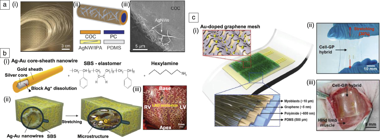
Despite this successful in vivo demonstration, even the slightest exposure of tissues and the spinal cord to Ag metal can cause toxicity issues, particularly for long-term implantation. Therefore, further modification of the Ag NWs is required to preserve the high conductivity and stretchability of the Ag NW network, while increasing the biocompatibility of the corresponding implantable devices. Choi et al. developed a stretchable Ag-Au nanocomposite composed of Au-shell-coated Ag NWs mixed with a thermoplastic polymer, styrene-butadiene-styrene rubber (Figure 2b), to address this issue.Reference Choi, Han, Jung, Hwang, Lim, Bae, Park, Tschabrunn, Lee, Bae, Yu, Ryu, Lee, Park, Kang, Lee, Nezafat, Hyeon and Kim103 The resulting composite material exhibited high conductivity due to the percolation network of the high-aspect-ratio Ag-Au NWs and the high intrinsic conductivity of the Ag NWs. The inert Au shell effectively protected the core Ag NWs from oxidation and dissolution, which maintains their high conductivity over the long term and suppresses the cytotoxicity of the Ag NWs. As a result, a stable electrical conductivity could be achieved even when the Ag-Au nanocomposite was fully stretched to a tensile strain of 840%. Finally, the Ag-Au nanocomposite was applied to cardiac signal measurement and electrical stimulation of a swine heart after appropriate patterning and device fabrication through a molding process. This novel highly conductive, biocompatible, and stretchable material provides new opportunities for advanced implantable bioelectronic systems.
Implantable devices based on hybrid nanomaterials can be integrated with cells and tissues before implantation in vivo to realize the multifunctionality of diagnosis and therapy as well as enhanced biocompatibility.Reference Lee, Lim, Shi, Tang, Wang, Lim and Loh105–Reference Kim, Cho, Cho, Qiao, Rhim, Soh, Kim, Choi, Choi, Park, Hwang, Hyeon, Choi, Lu and Kim107 The ultimate goal of such multifunctional devices is to develop a soft system for long-term implantation for simultaneous measurement of various electrophysiological signalsReference Sunwoo, Lee, Bae, Shin, Kim, Joo, Choi, Suh, Kim, Choi and Kim108 and feedback electrical stimulation therapies while providing a high level of long-term biocompatibility. Kim et al. reported a multifunctional cell culture platform integrated with a graphene nanohybrid, cell sheets, impedance sensors, and an electrical stimulator for recording electrophysiological signals and regenerating injured muscle tissues via electrical stimulation (Figure 2c).Reference Kim, Cho, Cho, Wang, Park, Lee, Hyeon, Lu, Choi and Kim109 Au NP-doped graphene electrodes in a buckled mesh-patterned design with sheets of immortalized mouse myoblast (primordial muscle cell) cell lines (C2C12 myoblasts) on top were used as a biointerface to the injured muscle tissues of an animal model. This ultrathin and stretchable device structure not only showed conformal device–tissue integration, but also improved the regeneration of injured muscle tissues with no immune response, thus overcoming the intrinsic limitations of bulky and rigid conventional implantable device–tissue interfacing devices.
Semiconducting nanomaterials-based wearable bioelectronics
Conventional electronic systems are typically based on single-crystal silicon (Si), which has been the most widely used semiconducting material in electronics and offers diverse benefits such as low cost, facile channel doping control, excellent processability compatible with mass production, and long-term reliability, including stability in air. However, the thick and rigid Si currently used in conventional electronic devices is not suitable for use in wearable bioelectronics. These limitations can be overcome through the use of Si nanomembranes (Si NMs) with thickness range in the hundreds of nanometers.Reference Kim, Ahn, Choi, Kim, Kim, Song, Huang, Liu, Lu and Rogers110,Reference Kim, Lee, Shim, Ghaffari, Cho, Son, Jung, Soh, Choi, Jung, Chu, Jeon, Lee, Kim, Choi, Hyeon and Kim111 Their ultrathin structure dramatically decreases flexural rigidity and thus allows flexibility, foldability, and high performance even under mechanical deformation, particularly when combined with elastomeric substrate/encapsulation layers, neutral mechanical plane (a layer within a structure that is not under stress), and serpentine shape interconnections.
Kim et al. have reported that Si NM-based epidermal devices can achieve conformal contact and complete adhesion on human skin based on van der Waals interactions alone, thereby extending high performance to a wearable format (Figure 3a).Reference Kim, Lu, Ma, Kim, Kim, Wang, Wu, Won, Tao, Islam, Yu, Kim, Chowdhury, Ying, Xu, Li, Chung, Keum, McCormick, Liu, Zhang, Omenetto, Huang, Coleman and Rogers112 The ultrathin epidermal devices were integrated into a multifunctional system that consists of sensors (temperature, strain, and electrophysiological parameters), microscale light-emitting diodes (LEDs), active/passive circuit elements (transistors, diodes, and resistors), wireless power coils, and radio frequency (RF) communication units (high-frequency inductors, capacitors, oscillators, and antenna). The system was integrated onto a thin (∼30 μm) elastomeric sheet based on modified silicone with a low Young’s modulus (∼60 kPa) for conformal lamination on human skin. The stretchability of the system was enhanced using neutral mechanical plane configurations and unique geometrical designs based on a filamentary serpentine (FS) structure. The combination of FS geometries and device islands connected by FS interconnects allowed minimization of the system modulus and thus conformal adhesion to skin.
Semiconducting nanomaterial-based wearable bioelectronics. (a[i]) Demonstration platform for multifunctional electronics with physical properties matched to the epidermis. Epidermal electronic system (EES) (ii) partially and (iii) fully peeled away from the skin; inset shows a representative cross-sectional illustration of the structure with the neutral mechanical plane (NMP). Reprinted with permission from Reference Reference Kim, Lu, Ma, Kim, Kim, Wang, Wu, Won, Tao, Islam, Yu, Kim, Chowdhury, Ying, Xu, Li, Chung, Keum, McCormick, Liu, Zhang, Omenetto, Huang, Coleman and Rogers112. © 2011 AAAS. (b[i]) Schematics of real-time wearable cardiac-monitoring system consisting of (ii) electrocardiogram (ECG) sensor, (iii) single-walled carbon nanotube-(CNT) based amplifier, and (iv) color-tunable organic light-emitting diode (OLED) display. Reprinted with permission from Reference Reference Koo, Jeong, Shim, Son, Kim, Kim, Choi, Hong and Kim119. © 2017 American Chemical Society. (c[i]) Three-dimensional schematic of the desired morphology composed of embedded nanoscale networks of polymer semiconductor. (ii) Photograph of a CONPHINE-1 film (blue area) at 100% strain on a rubber substrate. Reprinted with permission from Reference Reference Xu, Wang, Wang, Zhu, Luo, Lin, Gu, Chen, Feig, To, Rondeau-Gagne, Park, Schroeder, Lu, Oh, Wang, Kim, Yan, Sinclair, Zhou, Xue, Murmann, Linder, Cai, Tok, Chung and Bao124. (iii) Atomic force microscope phase images of the top and bottom interfaces of the conjugated-polymer/elastomer phase separation-induced elasticity (CONPHINE)-1 film with 70 wt% polystyrene-block-poly(ethylene-ran-butylene)-block-polystyrene (SEBS). © 2017 AAAS. (d[i]) Data flow between the integrated electronic components and display. (ii) Ultrathin quantum dot light-emitting diode (QLED) 16 × 16 display on deformed skin; insets show three color displays: red, green, and blue. (iii) Demonstration of its waterproof property stable operation in (inset) crumpled and (iv) rolled form. Reprinted with permission from Reference Reference Kim, Shim, Yang, Choi, Kim, Kim, Hyeon and Kim12. © 2017 Wiley. Note: RF, radio frequency; EMG, electromyography; MOS, metal oxide semiconductor; PE, polyethylene; PI, polyimide.

In addition to the ultrathin structure of Si NMs, which provides soft electronics with the desired deformation capability, the percolated network structure of semiconducting CNTs can serve as a channel for transistors in wearable/deformable devices.Reference Son, Koo, Song, Kim, Lee, Shim, Park, Lee, Kim and Kim113–Reference Cao, Kim, Pimparkar, Kulkarni, Wang, Shim, Roy, Alam and Rogers115 Semiconducting CNTs show excellent electrical properties, good uniformity over large areas, and robust performance under mechanical deformation due to the self-reconfiguration of the highly percolated network under an applied strain.Reference Artukovic, Kaempgen, Hecht, Roth and Gruner116–Reference Koo, Song and Kim118
Koo et al. described a wearable electrocardiogram (ECG) monitor containing an ultrathin electrode and a p-type metal oxide semiconductor (MOS) CNT signal amplifier, which allowed continuous ECG monitoring on human skin and real-time colorimetric display of the retrieved ECG signals through an ultrathin voltage-dependent color-tunable organic LED (Figure 3b).Reference Koo, Jeong, Shim, Son, Kim, Kim, Choi, Hong and Kim119 The signal amplifier consists of p-MOS inverters based on four p-type CNT transistors. The well-percolated networks of the semiconducting CNT channel and the ultrathin electrode endowed these CNT-based electronics with stable operation under various deformation conditions. The integration of CNT-based sensors and amplifiers increased the signal-to-noise ratio and ECG signal measurement accuracy, which demonstrated the suitability of CNT electronics for use in next-generation wearable bioelectronics.
Despite extensive research efforts on stretchable electronics, areal density issues have arisen in stretchable devices with the incorporation of structural designs such as wavy and serpentine-shaped interconnections. Although such designs allow the use of high-quality ultrathin inorganic materials in stretchable devices, which generally exhibit electrical performance superior to those of organic materials, the practical utilization of these designs is hindered by the loss of areal density.
In this respect, recently developed intrinsically stretchable organic materials hold great promise.Reference Liang, Li, Chen, Hajagos, Ren, Chou, Hu and Pei120–Reference Trung and Lee123 Xu et al. showed that an organic semiconducting polymer film can simultaneously maintain high stretchability and high field-effect mobility by virtue of a nanoconfinement effect. As shown in Figure 3c,Reference Xu, Wang, Wang, Zhu, Luo, Lin, Gu, Chen, Feig, To, Rondeau-Gagne, Park, Schroeder, Lu, Oh, Wang, Kim, Yan, Sinclair, Zhou, Xue, Murmann, Linder, Cai, Tok, Chung and Bao124 nanoconfinement of polymer chains was achieved via the formation of nanofibrils inside a soft, deformable elastomer. The connectivity between the aggregates of the nanofibrils allowed for good charge transport in the deformable elastomer. A high-mobility semiconducting polymer with a soft elastomeric medium was used. The increased number of polymer chains under nanoconfinement reduced the modulus of the conjugated polymer and improved stretchability up to 100% strain without affecting mobility. Subsequently, nanoconfinement was applied to fully stretchable transparent transistors to achieve high biaxial stretchability with minimal change of ON-current. Finally, the developed approach was used to fabricate a skin-like finger-mounted wearable sensing device to drive an LED, showing promise for diverse applications in wearable bioelectronics.
Stretchable semiconducting nanomaterials have also been applied to develop deformable displays, realizing user-interactive biomedical electronic systems. Such wearable displays can show stored health information and biosignals measured by the wearable bioelectronics in real time. Deformable display applications utilize ultrathin light-emitting layers such as with quantum dotReference Choi, Yang, Kang, Kim, Choi, Park, Kim, Chae, Kim, Kim, Hyeon and Kim8,Reference Choi, Yang, Kim, Dai, Kim, Seung, Kale, Sung, Park, Lu, Hyeon and Kim9 (QD) layers. Ultrathin QD layers have superb optoelectronic properties, chemical stability, and mechanical reliability (e.g., high brightness at a low operating voltage, good stability in air, high thermal reliability, printability on various substrates, and excellent mechanical deformability). Kim et al. developed a user-interactive wearable display integrated with biosensing and electronics components (Figure 3d).Reference Kim, Shim, Yang, Choi, Kim, Kim, Hyeon and Kim12 This passive-matrix (16 × 16) QD display was fabricated using CdSe-based (QLEDs) and co-integrated into a wearable electronic system that consisted of various physiological sensors and driving circuits. The previously mentioned properties of QDs and the ultrathin thickness (≈5.5 μm) of the QLED display allowed for a high electroluminescence brightness of the wearable display, up to 44,719 cd m2 at 9 V. As a result, the ultrathin QLED display could be safely operated at low temperatures, which is important for a wearable system mounted on human skin. Further integration of this display with flexible circuits allowed for the realization of an advanced wearable system with user controllability/interactivity.Reference Koo, Kim, Shim, Kim and Kim125
Semiconducting nanomaterials-based implantable bioelectronics
Semiconducting nanomaterials have been applied to implantable bioelectronics. Nanoscale semiconductors whose electron mobility is high enough to fabricate electronic devices have been used for electronic implants.Reference Liu, Fu, Cheng, Hong, Zhou, Jin, Duvvuri, Jiang, Kruskal, Xie, Suo, Fang and Lieber126–Reference Kim, McCall, Jung, Huang, Siuda, Li, Song, Song, Pao, Kim, Lu, Lee, Song, Shin, Al-Hasani, Kim, Tan, Huang, Omenetto, Rogers and Bruchas128 There are many aspects to consider regarding the use of semiconducting nanomaterials for implantable bioelectronics. We focus on two interesting recent breakthroughs achieved using semiconducting nanomaterials, one in efficient power management of electronic implantsReference Niu, Wang, Yi, Zhou and Wang129–Reference Zheng, Zou, Zhang, Liu, Wang, Jin, Ouyang, Li and Wang132 and the other in bioresorbable implantable devices.Reference Kang, Murphy, Hwang, Lee, Harburg, Krueger, Shin, Gamble, Cheng, Yu, Liu, McCall, Stephen, Ying, Kim, Park, Webb, Lee, Chung, Wie, Gujar, Vemulapalli, Kim, Lee, Cheng, Huang, Lee, Braun, Ray and Rogers133–Reference Yu, Kuzum, Hwang, Kim, Juul, Kim, Won, Chiang, Trumpis, Richardson, Cheng, Fang, Thomson, Bink, Talos, Seo, Lee, Kang, Kim, Lee, Huang, Jensen, Dichter, Lucas, Viventi, Litt and Rogers135
One major issue in implantable bioelectronics is the long-term power supply, as electric power must be continuously supplied to various sensors (ECG/electrocorticography [ECoG]) and actuators (pacemaker/deep brain stimulator) as well as to electronic circuits in the implantable system. This requires frequent replacement of the entire implantable device, including the battery, which requires painful, expensive, and undesired surgeries (e.g., surgical replacement of conventional cardiac pacemakers every seven years). In this regard, the piezoelectric property of semiconducting zinc oxide (ZnO) nanowires,Reference Wang and Song136–Reference Ha, Lim, Park, Um, Lee and Ko140 which originates from the mechanical–electric coupling of piezoelectric nanomaterials, can be used to generate power inside the body and drive an implantable nanosensing system. The ZnO-based nanogenerator exploits movements of the heart, respiration, and other organs to generate power inside animal bodies. Li et al. used ZnO NWs to fabricate an implantable energy harvester based on an (AC) nanogenerator and demonstrated energy harvesting in vivo from the motions induced by the breathing and heartbeat of a rat (Figure 4a).Reference Li, Zhu, Yang, Wang and Wang141
Semiconducting nanomaterials-based implantable bioelectronics. (a[i]) Single-wire generator (SWG) implanted into a live rat’s heart diaphragm, which (ii) drives the SWG to periodically bend and produce AC (alternating current) power output. The dashed line box indicates the location of a SWG. (iii) Current–voltage (I–V) characteristics of the SWG, showing the presence of Schottky contact. (iv) Current output measured from a SGW in vivo. Inset plot shows zoomed-in view of the data from the red rectangular box. Reprinted with permission from Reference Reference Li, Zhu, Yang, Wang and Wang141. © 2010 Wiley. (b[i]) Ultrasensitive endocardial pressure sensor (SEPS) in (top) bending and (bottom) original state; (ii, bottom left) minimally invasive surgery with a (bottom right) digital radiography image of the heart implanted with a device by (top) surgical delivery system integration. Reprinted with permission from Reference Reference Liu, Ma, Ouyang, Shi, Li, Jiang, Xie, Qu, Zou, Huang, Li, Zhao, Tan, Yu, Fan, Zhang, Wang and Li142. © 2018 Wiley. (c[i]) Schematic exploded view of a passive, bioresorbable neural electrode array for electrocorticography (ECoG) and subdermal encephalogram measurements. (Inset) The optical image of the electrodes show the sensing (Si nanomembranes) and insulating (SiO2) regions. (ii) Photographs of a four-channel bioresorbable electrode array placed on the cortical surface on the left hemisphere of a rat, and (iii) an array wrapped around a cylindrical tube with a radius of 2 mm. Reprinted with permission from Reference Reference Yu, Kuzum, Hwang, Kim, Juul, Kim, Won, Chiang, Trumpis, Richardson, Cheng, Fang, Thomson, Bink, Talos, Seo, Lee, Kang, Kim, Lee, Huang, Jensen, Dichter, Lucas, Viventi, Litt and Rogers135. © 2016 Springer Nature. (d[i]) A bioresorbable magnesium alloy stent strut integrated with (ii) ceria nanoparticles (NPs) for (iii) catalytic reactive oxygen species (ROS) scavenging, where superoxide and hydrogen peroxide molecules were used to mimic increased ROS levels in cardiovascular systems during angioplasty. Reprinted with permission from Reference Reference Son, Lee, Lee, Ghaffari, Yun, Kim, Lee, Cho, Yoon, Yang, Lee, Qiao, Ling, Shin, Song, Kim, Kim, Lee, Kim, Soh, Lee, Hwang, Nam, Lu, Hyeon, Choi and Kim147. © 2015 American Chemical Society. Note: MSN, mesoporous silica nanoparticle; NIR, near infrared; PLA, poly(lactic) acid; RRAM, resistive random-access memory; Au NR@MSN, Au nanorod core with a mesoporous silica nanoparticle shell; PLGA, poly(lactic-co-glycolic acid).

Another example of a self-powered nanosensing system is presented in Figure 4b, which shows a nano-poly(tetrafluoroethylene) (PTFE) film-basedReference Liu, Ma, Ouyang, Shi, Li, Jiang, Xie, Qu, Zou, Huang, Li, Zhao, Tan, Yu, Fan, Zhang, Wang and Li142 flexible and ultrasensitive endocardial pressure sensor (SEPS). The SEPS was based on a triboelectric nanogenerator that converts the mechanical energy of blood flow within the heart chambers into electricity. Highly sensitive (1.195 mV mmHg–1) real-time monitoring of endocardial pressure to detect cardiac arrhythmias was successfully achieved by implanting the device into the left ventricle and left atrium of a porcine model. The SEPS could be integrated with a surgical catheter for minimally invasive deployment. High-sensitivity pressure sensing was achieved by modifying one of the triboelectric layers, the nano-PTFE film, to have a higher surface charge density with corona discharge and by adding an ethylene-vinyl acetate copolymer film as a spacer layer for more effective contact and separation between the two films. The SEPS showed potential for self-powered detection of cardiovascular diseases.
In addition to the long-term power supply issue, the chronic inflammation caused by the implanted device and corresponding secondary surgery for removal of implanted devices are other major issues. Bioresorbability of the implanted device can solve this issue. Medical implants made of bioresorbable materials can decompose into biocompatible materials that are absorbed by the human body, thus avoiding chronic inflammation due to long-term implantation and minimizing any secondary surgery to remove the implanted device after use. One good example is the biodegradable stent applied for cardiovascular diseases.Reference Ormiston and Serruys143 However, current bioresorbable commercial medical implants do not contain electronics, and their role is limited to structural support. To develop such bioresorbable electronic devices, the development of bioresorbable semiconducting materials is required.Reference Hwang, Tao, Kim, Cheng, Song, Rill, Brenckle, Panilaitis, Won, Kim, Song, Yu, Ameen, Li, Su, Yang, Kaplan, Zakin, Slepian, Huang, Omenetto and Rogers144–Reference Kwon, Lee, Ko, Sunwoo, Lee, Jo, Choi, Hwang and Kim146
Yu et al. applied Si NM as a bioresorbable semiconducting material to a multiplexed neural array in a bioresorbable format for monitoring ECoG and subdermal encephalograms (Figure 4c).Reference Yu, Kuzum, Hwang, Kim, Juul, Kim, Won, Chiang, Trumpis, Richardson, Cheng, Fang, Thomson, Bink, Talos, Seo, Lee, Kang, Kim, Lee, Huang, Jensen, Dichter, Lucas, Viventi, Litt and Rogers135 Specifically, bioresorbability of the Si NMs was achieved due to the hydrolysis of the Si NM when immersed in biofluids, thereby eliminating the need for additional surgery to remove the implanted recording devices. Such robust capabilities in bioresorbable implantable bioelectronics can be employed for advanced clinical problems of post-operation monitoring of neural activities.
The previously discussed Si NM bioelectronics were developed for sensing and thus allowed real-time biosignal monitoring. However, other system functions such as storage of data and feedback treatment via localized drug delivery were not included. Son et al. have developed a multifunctional bioresorbable electronic stent (Figure 4d).Reference Son, Lee, Lee, Ghaffari, Yun, Kim, Lee, Cho, Yoon, Yang, Lee, Qiao, Ling, Shin, Song, Kim, Kim, Lee, Kim, Soh, Lee, Hwang, Nam, Lu, Hyeon, Choi and Kim147 It consists of a bioresorbable magnesium alloy stent strut integrated with ceria nanoparticles (ceria NPs) for catalytic reactive oxygen species (ROS) scavenging, where superoxide and hydrogen peroxide molecules were used to mimic increased ROS levels in cardiovascular systems during angioplasty (Figure 4d[iii]). The system consists of an Au nanorod core with a mesoporous silica nanoparticle shell for thermal stimuli responsive drug delivery, flow and temperature sensors for blood flow and temperature sensing, and a wide-bandgap semiconducting MgO-based ReRAM for data storage. The magnesium alloy stent strut was also used as an antenna for wireless power transmission and data communication. This multifunctional smart stent system measured blood flow, transferred data wirelessly to an external analysis system, released anti-stenosis drugs by Au NR-based local hyperthermia, and effectively scavenged ROS by catalytic effects of ceria NPs. These combined functions are important for the monitoring and prevention of in-stent thrombosis.
Unconventional nanomaterials for next-generation bioelectronics
Although methods for the synthesis and modification of nanomaterials have become elaborate and reached the level of mass production, it is still difficult to simultaneously meet all the requirements of diverse biomedical applications, such as biocompatibility, stretchability, transparency, electrical performance, long-term reliability, and even therapeutic capability with a single conventional nanomaterial. Consequently, recent investigations on bioelectronics have focused on the careful selection of unconventional nanomaterials corresponding to specific biomedical applications and the use of efficient integration techniques to integrate these unconventional nanomaterials in a single multifunctional system to achieve the diverse performance requirements of biomedical applications.
Lee et al. developed a multifunctional smart endoscope in which graphene-hybrid-based transparent flexible sensors were integrated on a surgical endoscope and combined with theranostic nanoparticles for tumor imaging and therapy (Figure 5a).Reference Lee, Lee, Song, Cho, Ghaffari, Choi, Kim, Lee, Ling, Lee, Yu, Choi, Hyeon and Kim82 The transparent flexible sensors and actuators on the smart endoscope are based on a transparent hybrid conductor that consists of patterned graphene, Au NPs, iridium oxide (IrOx) thin film, and Ag NWs. The multifunctional device was capable of sensing of tumor tissues and applying RF ablation to the detected tumor tissue. Integration with therapeutic nanoparticles also allowed local imaging of the remaining tumor tissue and the application of photodynamic and photothermal therapy to the imaged tumor. Due to the transparency of the graphene-based hybrid conductor, all sensing, imaging, and therapy procedures inside the body could be observed using the endoscope camera through the transparent multifunctional device on the endoscope.
Unconventional nanomaterials for next-generation bioelectronics. (a[i]) Multifunctional endoscope system based on transparent bioelectronics devices and theranostic nanoparticles. (Right) The optical image shows the position of detailed sensors and their transparency. (ii) Images of the tumor captured from the endoscope. The cases of (left) transparent graphene (GP)-based device and (right) metal-based device. Reprinted with permission from Reference Reference Lee, Lee, Song, Cho, Ghaffari, Choi, Kim, Lee, Ling, Lee, Yu, Choi, Hyeon and Kim82. © 2015 Springer Nature. (b[i]) Diabetes patch composed of sweat-control, sensing, and therapy components. (ii) Optical image of the GP hybrid electrochemical device array on human skin with perspiration, and (iii[left]) optical microscope images of GP hybrid after poly(3,4-ethylenedioxythiophene) electrodeposition and (right) corresponding scanning electron microscope image of the region in the red box. Reprinted with permission from Reference Reference Lee, Choi, Lee, Cho, Ghaffari, Wang, Choi, Chung, Lu, Hyeon, Choi and Kim54. © 2016 Springer Nature. (c[i]) Schematic of multifunctional self-healable electronic skin composed of strain monitor, electrocardiogram (ECG) sensor, and electroluminescent cells. (ii) Multifunctional self-healable electronic skin device on skin while operating a light-emitting electrochemical cell (LEC). Reprinted with permission from Reference Reference Son, Kang, Vardoulis, Kim, Matsuhisa, Oh, To, Mun, Katsumata, Liu, McGuire, Krason, Molina-Lopez, Ham, Kraft, Lee, Yun, Tok and Bao64. © 2018 Springer Nature. Note: TP, transparent; PDT, photodynamic; PTT, photothermal; NP, nanoparticle; SHP, self-healing polymer; NW, nanowire; μPs, microparticles.

Such material and integration technology for hybrids of unconventional nanomaterials can be also extended to wearable bioelectronics. Graphene-based hybrid nanomaterials were applied to fabricate wearable patch-type sensors (Figure 5b).Reference Lee, Choi, Lee, Cho, Ghaffari, Wang, Choi, Chung, Lu, Hyeon, Choi and Kim54 The transparent conducting hybrid material was used as a strain gauge or temperature sensor. After further functionalization with glucose oxidase and a redox mediator, it was used as a glucose sensor to detect glucose level in sweat. Functionalization with polyaniline and poly(3,4-ethylenedioxythiophene) poly(styrene sulfonate) enabled fabrication of a pH and humidity sensor. The Au particles formed scattered clusters on the patterned graphene, providing a large electrochemically active surface area, which resulted in improved electrochemical sensitivity of the various sensors. The graphene hybrid endowed transparency to the system, and a skin-like appearance could be achieved even while wearing the patch.
In addition to conventional flexible and stretchable nanomaterials, autonomously self-healable materialsReference Son, Kang, Vardoulis, Kim, Matsuhisa, Oh, To, Mun, Katsumata, Liu, McGuire, Krason, Molina-Lopez, Ham, Kraft, Lee, Yun, Tok and Bao64,Reference Li, Wang, Keplinger, Zuo, Jin, Sun, Zheng, Cao, Lissel, Linder, You and Bao83,Reference Kang, Son, Wang, Liu, Lopez, Kim, Oh, Katsumata, Mun, Lee, Jin, Tok and Bao84,Reference Li, Liang, Li, Ren, Hu, Li, Qi and Pei148,Reference Sun, You, Jiang, Guan, Fang, Deng, Chen, Luo and Peng149 have also been intensively researched. Son et al. recently observed that broken conductive CNT and Ag NW networks could be autonomously reconstructed at room temperature, owing to the dynamic nature of a self-healing polymer matrix. The self-recovery properties originate from the low glass-transition temperature and hydrogen bonding interactions of the self-healing polymer chains (Figure 5c).Reference Son, Kang, Vardoulis, Kim, Matsuhisa, Oh, To, Mun, Katsumata, Liu, McGuire, Krason, Molina-Lopez, Ham, Kraft, Lee, Yun, Tok and Bao64 Efficient dissipation of strain energy in the polymer made the previously discussed nanocomposites more mechanically reliable than conventional elastomers. More importantly, self-healing nanomaterials capable of self-bonding allow facile assembly of two-dimensional and three-dimensional electronic modules without the use of heat, light, or complex processes.Reference Kang, Son, Vardoulis, Mun, Matsuhisa, Kim, Kim, Tok and Bao150 Utilizing the self-bonding assembly, the authors developed a multifunctional self-healable bioelectronic system that comprised transparent stretchable electrodes, sensors, and light-emitting capacitor devices, which could measure physiological signals and visualize the measured signals.Reference Son, Kang, Vardoulis, Kim, Matsuhisa, Oh, To, Mun, Katsumata, Liu, McGuire, Krason, Molina-Lopez, Ham, Kraft, Lee, Yun, Tok and Bao64
Conclusions
Next-generation wearable and implantable devices will consist of closed-loop biointegrated systems, featuring functionality including continuous recording of physiological and electrophysiological signals, on-site amplification of recorded data, precise analysis of disease patterns, real-time display of the analyzed data, and feedback point-of-care therapy based on the diagnosis. However, this goal has not yet been achieved due in large part to the absence of appropriate materials and efficient integration methods capable of satisfying the various performance requirements of diverse biomedical applications (e.g., biocompatibility, stretchability, high electrical performance, transparency, therapeutic functionality, and self-healing). In this respect, new strategies for functional nanomaterial synthesis and the integration of the synthesized nanomaterials should be developed while utilizing well-established existing technologies to process these materials and fabricate devices using them. In this article, we have introduced and summarized such research efforts for next-generation wearable and implantable bioelectronic devices according to the properties of the materials, (i.e., conducting, semiconducting, and unconventional nanomaterials). The development and integration of such materials into novel flexible and stretchable bioelectronics is expected to revolutionize clinical medicine in the near future.
Acknowledgments
J.-K.S. and K.D. contributed equally to this work. D. Son and D.-H. Kim are the corresponding authors. This work was supported by IBS-R006-A1. This work was also supported by KIST intramural grant (2E29680) and the Ministry of Trade Industry & Energy (MOTIE, Korea), Ministry of Science & ICT (MSIT, Korea), and Ministry of Health & Welfare (MOHW, Korea) under Technology Development Program for AI-Bio-Robot-Medicine Convergence (20001655).

Jun-Kyul Song is a doctoral candidate in the School of Chemical and Biological Engineering at Seoul National University, Republic of Korea. He received his BS degree in chemistry in 2012 from the University of Illinois. His current research focuses on carbon-nanotube-based electronic and optoelectronic devices for next-generation soft electronics. Song can be reached by email at jksong0513@snu.ac.kr.

Kyungsik Do is a doctoral candidate in the School of Chemical and Biological Engineering at Seoul National University, Republic of Korea. He received his BS degree in chemical engineering in 2014 from Hanyang University, Republic of Korea. His current research focuses on oxide-based electronics and energy devices for soft electronics. Do can be reached by email at ksdo573@snu.ac.kr.

Ja Hoon Koo is a doctoral candidate in the Interdisciplinary Program for Bioengineering at Seoul National University, Republic of Korea. He received his BS degree in 2010 and his MS degree in 2013 in electrical and electronics engineering from Yonsei University, Republic of Korea. He was a research intern at Stanford University from 2013 to 2014. His current research focuses on carbon-nanotube-based electronic and optoelectronic devices for next-generation soft electronics. Koo can be reached by email at kooco84@snu.ac.kr.

Donghee Son is a senior research scientist at the Biomedical Research Institute, Korea Institute of Science and Technology (KIST), Republic of Korea. He received his BS degree in physics in 2007 at Korea University, Republic of Korea, and his MS degree in the Interdisciplinary Program in Nanoscience and Technology, in 2009, at Seoul National University (SNU), Republic of Korea. He obtained his PhD degree in 2015 from the School of Chemical and Biological Engineering at SNU. From 2016 to 2017, he completed postdoctoral research at Stanford University. His current research focuses on self-healable and stretchable electronics for biomedical applications. Son can be reached by email at daniel3600@kist.re.kr.

Dae-Hyeong Kim is an associate professor at Seoul National University (SNU), Republic of Korea. He received his BS degree in 2000 and his MS degree in 2002 from the School of Chemical Engineering at SNU. He obtained his PhD degree in 2009 from the Department of Materials Science and Engineering at the University of Illinois at Urbana-Champaign. His research focuses on stretchable electronics for biomedical and energy applications. Kim can be reached by email at dkim98@snu.ac.kr.



