I. INTRODUCTION
Porous carbon materials, especially those containing nanopores, are widely used in many fields of science and technology, including catalysis,Reference Guha, Lu, Zawodzinski and Schiraldi1,Reference Yu, Kang, Yoon and Chai2 air separation,Reference Merritt, Rajagopalan and Foley3 energy storage,Reference Kim, Lee and Park4 double-layer capacitors,Reference Li, Jiang, Dou, Wu, Huang, Feng, Yang, Yu and Zhao5 and preparation of structural carbide ceramics.Reference Wang, Tan and Jiang6,Reference Xu, Qiao, Li, Yang, Liu and Lu7 Much effort has been made to develop carbon materials with improved properties, such as physical activation or chemical activation.Reference Teng and Wang8 Currently, the resulting porous carbon was mostly in the form of powder. Powder carbon materials with controlled pore shapes, sizes, and distributions were prepared by hard-templateReference Fuertes and Centeno9 and soft templateReference Zhai, Dou, Liu, Park, Ha and Zhao10,Reference Zhang, Deng, Wei, Sun, Gu, Bongard, Liu, Wu, Tu, Schüth and Zhao11 synthesis methods, which have been proven to be successful methods. Although carbonaceous powder materials have been widely investigated and used in the applications, monolithic types attract more and more interest because of their wide operation flexibility.Reference Lu, Hao, Sun, Zhang and Li12,Reference Fan, Hu, Maier, Adelhelm, Smarsly and Antonietti13 In many of these applications, integrated carbon monoliths are needed. For example, to prepare structural carbide ceramics,Reference Hozer, Lee and Chiang14 carbon monoliths are indispensable and the mechanical strength should be excellent.
Much effort has been made on the preparation of nanoporous monolithic carbon with high mechanical strength.Reference Yang, Shi, Liu, Xie, Jiang, Zhang, Yu, Tu and Zhao15,Reference Wang, Lin, Lin, Yin, Liang, Di, Fan, Jiang and Xiao16 Liu and his coworkersReference Liu, Liu, Yang, Huang and Liu17 prepared activated carbon honeycomb monoliths. The cold crushing strength was around 15 MPa. Soon later, homogeneous and crack-free porous carbon monoliths were prepared through a self-assembly of poly(benzoxazine-co-resol) and a carbonization process, whose compressive strength could reach 15.6 MPa.Reference Hao, Li, Qian, Wang, Zhang, Zhang, Wang, Schuth, Bongard and Lu18 However, these methods are time-consuming and the mechanical strength of these nanoporous monolithic carbons is still relatively poor.
A polymer blend method was a cost effective strategy to prepare carbons with a controlled pore structure and size. Yamazaki and coworkers found that,Reference Yamazaki, Kayama, Ikeda, Alii and Ichihara19 starting from miscible blends of phenol–formaldehyde resin (PF) and other polymers, nanostructured carbon with continuous pores was obtained. They investigated phase separation morphology which is formed from the PF/poly(methyl methacrylate) (PMMA) miscible blends. However, the effect of the PMMA content and type on the morphologies of porous carbon materials and the relationship between the nanostructure and mechanical strength have not been studied.
In our work, PF/PMMA blends were used as the precursor to fabricate porous carbon monoliths by curing and carbonization. The effect of the molecular weight of PMMA, reaction activity of PF, and content ratio of the compositions on the carbon structure was studied. And the relationship between the morphology of nanopores and compressive strength of carbonaceous monoliths was systematically investigated.
II. MATERIALS AND METHODS
A. Preparation of PF/PMMA blends
Three types of PF with different reaction activities used in our experiment were PF1, PF2, and PF3. All of them were prepared by a condensation polymerization reaction of phenol and formaldehyde catalyzed by Barium hydroxide Ba(OH)2 according to Mondragon's work.Reference Astarloa-Aierbe, Echeverría, Martin and Mondragon20 PMMA (M n = 24,000; 40,000; 61,000; 134,000; M n measured by GPC using a polystyrene standard) was purchased from Aldrich Chemical Co.
Typically, a designed amount of PMMA and 100 g of PF were dissolved in 100 g of a solvent mixture of methanol (50 g) and acetone (50 g) with magnetic stirring for 8 h at 40 °C, until the solution turned dark yellow. The solution was poured into glass molds to evaporate methanol/acetone at room temperature for 12 h, and then the samples were transferred into an oven at 120 °C for 2 h. The rigid body with various weight ratios was thus obtained.
B. Preparation of porous carbonaceous materials
The blends were put in the molds and cured at 180 °C for 4 h under a pressure of 10 MPa. Then, the samples were drawn out from molds. At last, the cured body was pyrolyzed by slowly ramping to 700 °C in a flowing nitrogen atmosphere, followed by cooling naturally to room temperature. In general, the heating rate was 1 °C/min and the samples were held at 700 °C for 1 h. The carbonized monolithic samples were labeled as PF1–700 for the sample PF1 carbonized at 700 °C, and so on.
C. Characterization of porous carbonaceous monoliths
To discuss the process of the structural changes during heat treatment, weight loss behaviors of cured PF/PMMA blend samples were examined by thermogravimetry (NETZSCH STA 409 PC; NETZSCH-Gerätebau GmbH, Selb, Germany). These samples were heated to 900 °C with a heating rate of 10 °C/min under a N2 atmosphere. The samples were quenched and cracked in liquid nitrogen. Fracture surfaces of the carbonaceous samples were sputtered with gold, and observed on a Hitachi S-4800 scanning electron microscope (Hitachi, Tokyo, Japan) at an accelerating voltage of 10 kV. After pre-evacuation for 5 h at 200 °C, the Brunauer–Emmett–Teller (BET) surface area (S BET) of porous carbon materials and pore sizes were characterized by using nitrogen adsorption–desorption isotherms with an automatic adsorption instrument (ASAP 2020; Micromeritics, Atlanta, Georgia) at 77 K. The collected data were subjected to the BET and Barrett–Joyner–Halenda treatments. The pore size distributions (PSDs) were obtained by intrusion/extrusion mercury measurements using a Micromeritics Autopore IV 9500 porosimeter with the following parameters: contact angle = 130° and mercury surface tension = 485 mN/m. According to the standard of ISO 604:2002, compressive strength testing was carried out on a Universal Testing Machine (Instron-1122; Instron, Pittsburgh, Pennsylvania) at a loading rate of 5 mm/min.
III. RESULTS AND DISCUSSION
A. Process of nanopore formation
Before curing, PF and PMMA blends were miscible with each other. With the curing reaction of PF proceeding, the molecular weight of PF increased, resulting in the miscibility of PF/PMMA blends decreasing and phase separation appearing between PF and PMMA components. The PF rich phase and PMMA rich phase formed. Cured PF/PMMA blends were carbonized to obtain carbon materials with nanopores, which reflected characteristics of phase separation behavior between PF and PMMA (Fig. 1).
Schematic outlines for preparation of nanoporous carbonaceous materials.

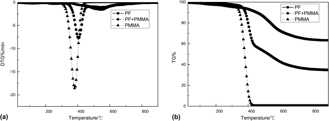
Thermal decomposition behavior of the cured blends was very important for the pore structure and properties of the carbon materials. Thermogravimetric analysis/derivative thermogravimetry (TG/DTG) measurements were carried out for the cured PF/PMMA resins under a N2 atmosphere and the results are given in Fig. 2. The DTG curve of PMMA showed an abrupt mass loss peak from 350 to 400 °C. Compared with PMMA, cured PF showed better thermal stability, and the main decomposition peak appeared between 400 and 800 °C. For cured PF/PMMA resin, its DTG curve gave two thermal decomposition peaks, revealing that the resin possessed an obvious two-stage decomposition style. The first decomposition peak is located at 400 °C due to the decomposition of the PMMA component, which played the role of forming pores (Fig. 2). The second peak corresponded to the thermal decomposition of the PF component, which played the role of forming char.
(a) DTG and (b) TG curves of PF, PMMA, and PF/PMMA blends.
Meanwhile, shrinkage occurred in the pyrolysis process. Below 700 °C, the shrinkage linearly increased with increasing temperature, which was due to the condensation and crosslinking reactions of polymeric structures to form glassy carbon.Reference Ko, Kuo and Chang21 Weight loss and shrinkage were relatively dominant. Therefore, the density decreased with increasing temperature. However, all the carbonized samples kept the shape of the molds very well. Although the total volume contracted after carbonization, the monoliths were macroscopically homogeneous and typically crack-free.
B. Effect of the molecular weight of PMMA
The morphology of nanopores was determined by the phase separation process between PF and PMMA. To obtain porous carbon materials with a designed nanoporous structure, it is very important to control phase separation behavior in the curing process. The molecular weight of PMMA was thought to be important for the structures of phase separation. PMMA with the number-average molecular weight varying from 24,000 to 134,000 was used to prepare the corresponding nanoporous carbon monoliths to investigate the effect of the molecular weight of PMMA on the density and pore structure of the carbonized products, and the characteristic parameters of the carbonized products are summarized in Table I.
Synthesis conditions and textural parameters of the porous carbon monoliths by changing the molecular weight of PMMA.
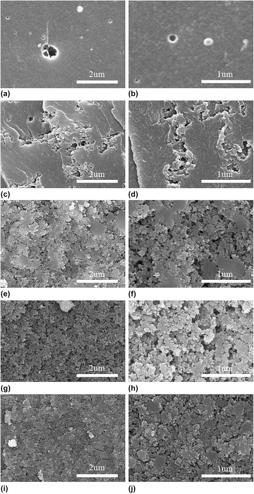
Morphologies of the carbonized products are illustrated in Fig. 3. When the molecular weight of PMMA was 24,000, the phase separation tended to be an isolated structure [Figs. 3(c) and 3(d)]. When the molecular weight of PMMA was 40,000, a locally connected and isolated pore structure was observed [Figs. 3(e) and 3(f)]. With the molecular weight of PMMA further increasing, the phase separation became a co-continuous structure gradually [Figs. 3(g) and 3(h)].
SEM images of porous carbon bulk; (a and b) PF1–700; (c and d) PF1-PMMA-2-700; (e and f) PF1-PMMA-4-700; (g and h) PF1-PMMA-6-700; (i and j) PF1-PMMA-13-700.
The details of the isolated and co-continuous phase separation structure forming process were discussed in this work, but the morphology of the pore structure could be controlled by changing the molecular weight of PMMA. The increase of the molecular weight of PMMA improved the viscosity of PF/PMMA blends, which suppressed phase separation of the blends. However, the increase of viscosity reduced miscibility between PF and PMMA, which accelerated phase separation of the blends. When the viscosity of PF/PMMA blends was low at onset point of phase separation, PMMA mobility was good and the components segregated to form an isolated phase structure. When the viscosity of blends was relatively high, the components were segregated to form a co-continuous structure.
As shown in Table I, the density of carbon monoliths varied with volume shrinkage. The carbon monoliths prepared from a low molecular weight of PMMA had larger volume shrinkage, inducing high density and low porosity. The density of carbon monoliths decreased from 1.18 to 0.81 g/cm3 with the molecular weight of PMMA increasing from 24,000 to 134,000. The volume shrinkage decreased from 60.6 to 52.9%, while the porosity increased from 29.7 to 55.7%.
The results of N2 absorption–desorption of the carbonaceous samples are shown in Fig. 4(a). N2 adsorption isotherms of these samples showed a steep uptake at a low relative pressure of P/P 0 < 0.1. These results suggested that micropores were generated in each sample. Expect for PF1–PMMA-2-700, adsorption–desorption behavior showed the intermediate between types II and IV, and hysteresis was clearly observed at a high relative pressure of P/P 0 > 0.8. These behaviors suggested the presence of mesopores. For PF1-PMMA-2-700, adsorption–desorption behavior showed type I. The PSDs of carbon monoliths changed depending on the PMMA content and were mostly distributed in the range of 0–100 nm. The PSDs increased with increasing molecular weight of PMMA, except for the PF1-PMMA-13-700. Many cracks appeared in the sample of PF1–PMMA-13-700. After calcination at 700 °C, the carbon structure of all the samples showed a relatively high BET surface area. The S BET values of PF1-PMMA-2-700, PF1-PMMA-4-700, PF1-PMMA-6-700 and PF1-PMMA-13-700 were 266, 453, 464, and 526 m2/g, respectively, which made the porous carbon monoliths to be a good candidate for the catalyst carrier.
Pore characterization of porous carbon materials; (a) N2 adsorption isotherms of carbonaceous materials and (b) PSDs of porous carbon samples obtained by mercury intrusion porosimetry.
During carbonization, pure PF resin decomposed and released a lot of volatile matter, including water vapor, CO2, CO, phenol, cresol, CH4, and so on. If these were no channels for the gases to escape in the carbon samples, inner stress caused by the gases could destroy the integrity of the carbon skeleton. Meanwhile, volume shrinkage usually occurred at the same time, especially in the temperature range of 500–600 °C, which was another origin of inner stress. Inner stress would decrease the mechanical properties of the carbon material.
However, in the carbon monoliths derived from PF/PMMA blends, PMMA decomposed first at 400 °C, and a lot of nanopores formed in the PF matrix, which provided channels for those volatile gases to escape and reduced the inner stress of the carbonaceous materials obviously. The nanopores also helped to scatter and absorb the stress and energy, keeping the integrity of the carbon skeleton, and ensuring the material high strength and modulus.
For PF1–700, only few isolated pores formed in the PF1–700. These were no escape channels, and the compressive strength of PF1–700 was only 5 MPa. Although the pore structure appeared in the PF1-PMMA-2-700, the morphology was an isolated structure which could not provide enough continuous escape channels. So inner stress could destroy the skeleton of carbon and the compressive strength was 11 MPa, lower than that of other types of PMMA. The carbonized matrix showed a combination of isolated and co-continuous structures in the PF1-PMMA-4-700. The compressive strength of PF1-PMMA-4-700 was around 13 MPa. With the molecular weight of PMMA increasing, the morphology became a co-continuous structure and the compressive strength of porous carbon monoliths increased further. For the PF1-PMMA-6-700, the compressive strength could reach 18 MPa. Many cracks appeared in the PF1-PMMA-13-700, and the compressive strength decreased, being 7 MPa. Compared with pure PF carbon samples, the escape channel in the porous carbon samples helped to protect the skeleton of the carbon matrix, enhancing whole compressive strength (Fig. 5).Reference Lei, Guo, Shi and Liu22
Mechanical characterization of carbon materials; (a) typical stress–strain curves of carbon materials, in which maximum stress is the compressive strength; (b) compressive strength of porous carbon monoliths.
C. Effect of reaction activity of PF
The PF/PMMA blends are homogeneous at the beginning of the curing process. The increasing molecular weight of the PF component in the curing process initiates reaction-induced phase separation to generate various heterogeneous morphologies. Then, these morphologies would be fixed at a certain stage of curing by gelation of PF. The reaction activity of PF may affect the gelation process, which could control the phase separation behavior. PF with different curing reaction activities was used to control the phase separation (Table II).
Synthesis conditions and textural parameters of the porous carbon monoliths by changing the reaction activity of PF.
Gel time reflected the reaction activity of PF. PF with shorter gel time possessed higher reaction activity. When the resin blends were heated in an oven at 120 °C for 2 h, the high reaction activity of PF1 may quickly gel, and the morphology would be fixed at the early stage. The size of the PF1 rich phase and PMMA rich phase was small. To the PF2, it did not gel so quickly, and it had enough time to form a bigger PF2 rich phase and PMMA rich phase. However, to the PF3, the reaction activity of PF3 was very low and miscibility of the PF3/PMMA blend decreased slowly. The PF3 rich phase and PMMA rich phase were not large. After the samples were put in the molds and cured at 180 °C under a pressure of 10 MPa, all the PF gelled quickly and these morphologies would be fixed. The size of the PF rich phase and PMMA rich phase remained unchanged.
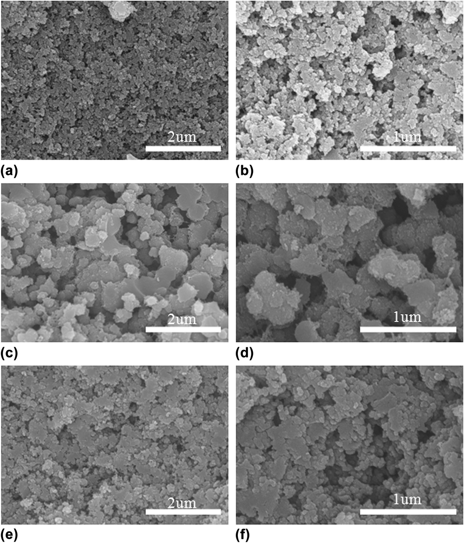
As shown in Fig. 6, a classical co-continuous structure formed in the three carbon samples after the reaction-induced phase separation. The size of co-continuous pores derived from PF2/PMMA was larger than that of PF1/PMMA and PF3/PMMA. In any case, the details of the phase separation process were still unclear. However, it was found that the morphology of the pore structure could be controlled by changing the reaction activity of PF and we could obtain porous materials with very fine continuous pores.
SEM images of porous carbon bulk; (a and b) PF1-PMMA-700; (c and d) PF2-PMMA-700; (e and f) PF3-PMMA-700.
The results of N2 absorption–desorption of the carbonaceous samples are shown in Fig. 7(a). The adsorption–desorption behavior of the samples showed the intermediate between types II and IV, and hysteresis was clearly observed at a high relative pressure of P/P 0 > 0.8. The PSD of PF2-PMMA-700 was larger than that of PF1-PMMA-700 and PF3-PMMA-700. The S BET values of PF1-PMMA-700, PF2-PMMA-700, and PF3-PMMA-700 were 464, 322, and 357 m2/g, respectively. The reaction activity of PF exhibited little effect on the characteristic parameters of samples (Table II). The volume shrinkage changed a little, being 62.3, 60.4 and 61.2%, respectively. The density and porosity of the carbon monoliths also changed a little.
Pore characterization of porous carbon materials; (a) N2 adsorption isotherms of carbonaceous materials and (b) PSDs of porous carbon samples obtained by mercury intrusion porosimetry.
Co-continuous pores appeared in the carbon materials derived from different PF. The compressive strength of porous carbon monoliths was much higher than that of the PF1–700. The compressive strength of PF1-PMMA-700, PF2-PMMA-700, and PF3-PMMA-700 was 18, 19, and 20 MPa, respectively (Fig. 8). The co-continuous structure kept the integrity of the carbon skeleton, resulting in significant improvement of compressive strength.
Mechanical characterization of carbon materials; (a) typical stress–strain curves of carbon materials, in which maximum stress is the compressive strength; (b) compressive strength of porous carbon monoliths.
D. Effect of the PMMA content
Various elements that influenced phase separation during curing of PF needed to be understood and the PMMA content was thought to be another factor. The influence of the PMMA content on the pore structure of carbonized products was studied with the weight fraction of PMMA varying from 0 to 50% (Table III).
Synthesis conditions and textural parameters of the porous carbon monoliths by changing the PMMA content.
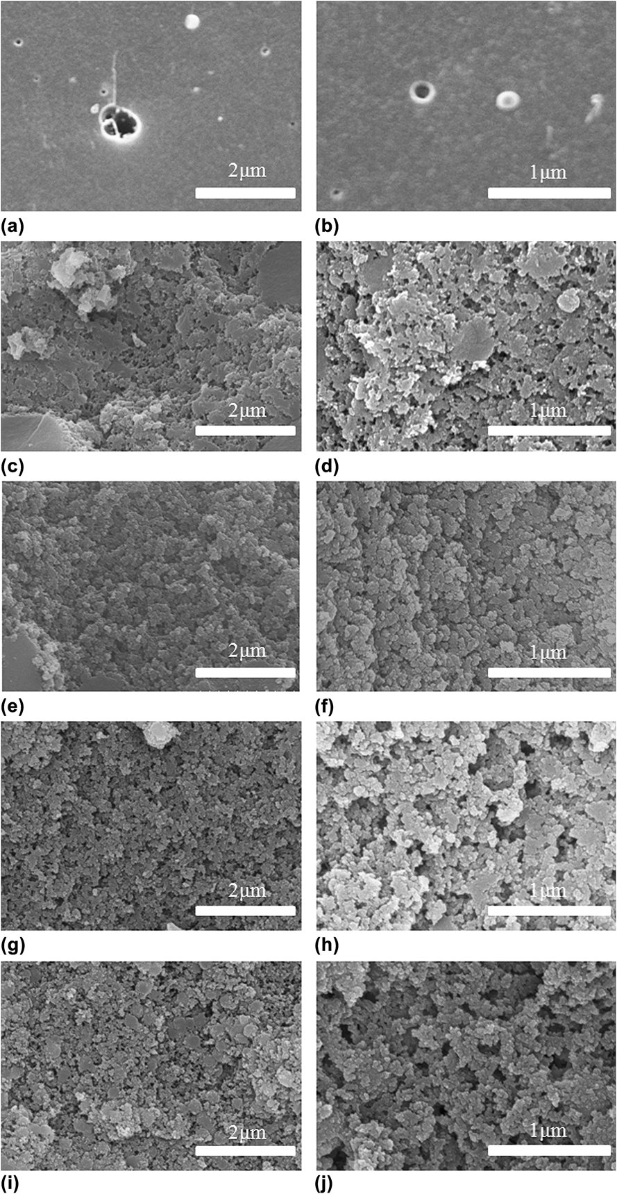
Figure 9 illustrates the micrographs of carbonized products. The amount of pores increased with the addition of the PMMA content. A classical co-continuous structure was shown in the PF1-PMMA-25%-700 [Figs. 9(e) and 9(f)]. With the increase of the PMMA content, PSDs increased and the carbonized matrix showed an interconnected-particle structure in the PF1-PMMA-50%-700 [Figs. 9(i) and 9(j)]. At lower PMMA concentrations [Figs. 9(c) and 9(d)], the pores were locally connected and isolated pores were also observed. It was found that we could obtain porous materials with very fine continuous pores in a wide composition range from PF/PMMA blends.
SEM images of porous carbon bulk; (a and b) PF1–700; (c and d) PF1-PMMA-17%-700; (e and f) PF1-PMMA-25%-700; (g and h) PF1–PMMA-33%-700; (i and j) PF1-PMMA-50%-700.
The results of N2 absorption–desorption of the carbonaceous samples are shown in Fig. 10(a). The adsorption–desorption behavior of the samples showed the intermediate between types II and IV, and hysteresis was clearly observed at a high relative pressure of P/P 0 > 0.9. The sizes of continuous “coral-like” pores changed depending on the PMMA content and were mostly distributed in the range of 0–100 nm. The porous carbon monoliths possessed a relatively high BET surface area. The S BET values of PF1-PMMA-17%-700, PF1-PMMA-25%-700, PF1-PMMA-33%-700, and PF1-PMMA-50%-700 were 436, 443, 464, and 512 m2/g, respectively. The density of carbon monoliths decreased from 1.36 to 0.73 g/cm3 with the content of PMMA increasing from 0 to 50%. The volume shrinkage and porosity increased from 39.9 to 55.5% and from 19.0 to 59.0%, respectively (Fig. 11).
Pore characterization of porous carbon materials; (a) N2 adsorption isotherms of carbonaceous materials and (b) PSDs of porous carbon samples obtained by mercury intrusion porosimetry.
Mechanical characterization of carbon materials; (a) typical stress–strain curves of carbon materials, in which maximum stress is the compressive strength; (b) compressive strength of porous carbon monoliths.
The compressive strength of PF1–700 was 5 MPa, much lower than that of porous carbon samples. For the PF1-PMMA-25%-700, PF1-PMMA-33%-700, and PF1-PMMA-50%-700 samples, they were a co-continuous structure, but the detailed morphology of the matrix differed from the continuous bulk structure in PF1–PMMA-25%-700 to the interconnected particle structure in the PF1-PMMA-50%-700 sample. The two structures will behave differently when the external force was added. The compressive strength of PF1-PMMA-25%-700 was 34 MPa. The force may be transferred along with the continuous bulk and absorbed by the nanopores. While the compressive strength of PF1-PMMA-33%-700 and PF1-PMMA-50%-700 successively decreased. The slip may easily occur between the interconnected particles, leading to the destruction of the materials.
IV. CONCLUSION
Nanoporous carbon monoliths with a tunable morphology and pore size were prepared using a simple method of carbonizing cured PF/PMMA blends. By changing the molecular weight of PMMA, reaction activity of PF and content ratio of compositions, different morphologies were obtained and the relationship between the pore structure and compressive strength was investigated. When the molecular weight of PMMA was varied from 24,000 to 134,000, the morphology of the corresponding porous carbon monoliths changed from an isolated pore structure to a co-continuous pore structure. When the reaction activity of PF increased, the morphology of porous carbon monoliths changed a little, but the PSDs increased first, and then decreased. When the content of PMMA was from 0 to 50%, we could obtain two kinds of continuous pore structures, i.e., the continuous bulk structure and the interconnected particle structure. The pore structure determined the compressive strength of porous carbon monoliths. A co-continuous structure could provide enough escape channels for volatile gases to escape, protecting the integrity of the carbon skeleton and enhancing the compressive strength of porous carbon monoliths. The highest compressive strength was 34 MPa and the S BET could reach 512 m2/g. Grounded on these characteristics, the nanoporous carbon monoliths possess low density, high mechanical strength, and high S BET, showing a promising prospect in some high technology applications, such as ablative materials.
ACKNOWLEDGMENTS
The authors acknowledge the support from the National Basic Research Program of China (2012CB933201) and National Natural Science Foundation of China (51403218 and 51473171).