I. INTRODUCTION
For many years, plastics have been prevalent in daily life and constitute one of the most important materials in the industry. Currently, in technology, it is recognized that both the bulk and surface properties of materials are important for industrial processes such as bonding, catalysis, or printing.Reference Liston, Martinu and Wertheimer1 Innovations in the preparation of the materials determine the development of new methods for modifying the outer surface.Reference Yasuda and Yasuda2–Reference Van Deynse, De Geyter, Leys and Morent4 The properties of the external surface are often different from the bulk properties. Modification of the external surface is used to prevent corrosion and improve the adhesion or bonding to other layers. This can be conducted by many methods such as plasma, chemical, mechanical, electrochemical, and radiative.
There are problems in printing on polymers, gluing and laminating them or depositing metallic layers onto them for several reasons. First of all, their surfaces are smooth. Second, contaminants from ambient air deposit themselves on the polymer’s surface. Moreover, components such as lubricants, plasticizers, and antioxidants can migrate to the surface of the tubes.Reference Żenkiewicz5 To increase the purity or surface free energy (SFE), the surface can be modified by a variety of chemical and physical methods.Reference Queffélec, Petit, Janvier, Knight and Bujoli6,Reference Kurella and Dahotre7 The main parameters changed during the modification are chemical composition, wettability, SFE, types of bonds in surface groups, and topography of the surface.Reference Grace and Gerenser8
Modification of the external surface of plastics using plasma methods have been investigated in recent years.Reference Opalinska, Ulejczyk, Karpinski and Schmidt-Szalowski9–Reference Bitar, Cools, De Geyter and Morent11 One of the methods is the use of plasma generated in a dielectric barrier discharge (DBD).Reference Kogelschatz12 Different kinds of materials can be modified, such as powder, foil, nonwoven fabric, or tubes.Reference Ren, Wang, Nie, Wang and Guo13–Reference Morent, De Geyter, Gengembre, Leys, Payen, Van Vlierberghe and Schacht15 Due to the relatively uncomplicated structure of the surface, the most common modified materials are foils. Since nonthermal plasma contains a mixture of reactive species, several different interactions between the plasma and a surface are possible, including oxidation,Reference Borcia, Anderson and Brown16 treatment,Reference Kostov, Nishime, Hein and Toth17 and etching. These different plasma–surface interactions have led to various ways of plasma-based surface modification.Reference Massines, Sarra-Bournet, Fanelli, Naudé and Gherardi18 FTIR-ATR investigations show the formation of C–O, C=O, and O–C–O OH groups.Reference Cernakova, Kovacik, Zahoranova, Cernak and Mazur19–Reference Moraczewski, Stepczyńska, Malinowski, Rytlewski, Jagodziński and Żenkiewicz22
Modification of a polymer’s surface depends on many parameters.Reference Rezaei, Dickey, Bourham and Hauser23 Van DeynseReference Van Deynse, De Geyter, Leys and Morent4 observed a reduction of the water contact angle with an increase in water vapor content in the gas used for the modification. In the DBD plasma with a constant energy density of 20 J/cm2, the water contact angle for pure argon, and a mixture of argon and 31% of water vapor were 51.4° and 35.6° respectively. The analysis of the foil surface by atomic force microscopy (AFM) indicated that due to the modification of the foil in argon with water vapor, the surface became rough, whereby the water contact angle decreased. Based on the results obtained with X-ray photoelectron spectroscopy (XPS), it was concluded that the decrease of the water contact angle was caused by the formation of C–O, C=O, O–C–O, or O–C=O groups on the surface of the foil.Reference Borcia, Anderson and Brown16,Reference Akishev, Grushin, Dyatko, Kochetov, Napartovich, Trushkin, Duc and Descours24,Reference Chen, Liu, Liu, Huang, Xia, Song, Xu, Sun and Liu25
Modification of low-density polyethylene (LDPE) foil in DBDReference Novak, Steviar, Popelka, Chodák, Mosnacek, Špírková, Janigová, Kleinoav, Sediacik and Slouf26 in oxygen caused a reduction of the water contact angle from 105° to approx. 40°, and the diiodomethane contact angle changed from 52° to 40°. The SFE increased from 36 to 54 mJ/m2. The values of its components were changed: dispersive from 0 mJ/m2 (for unmodified surface) to 32 mJ/m2, and polar from 36 to 20 mJ/m2. It was also observed that the elongation of the modification time had insignificant influence on the values of both SFE components. Based on the ATR–FTIR analysis, it was found that carbonyl groups were formed on the foil surface.
It was observed by ChiperReference Chiper, Nastuta, Rusu and Popa27 that a higher discharge power caused a steep decrease in the water contact angle. Contact angles changed insignificantly for energy density higher than 890 mJ/cm2 in the case of polyethylene (PE) and 640 mJ/cm2 in the case of PET. Moreover, the topography of the surface of the PE foil did not change significantly. By contrast, the surface of the PET foil had a substantially different topography after the modification with a large number of small hollows. Therefore, its roughness increased due to the treatment.
ŠvorčíkReference Švorčík, Kolarova, Slepicka, Mackova, Novotna and Hnatowicz28 found that the physical properties of polymers had major influence on how their surface was modified by a specific treatment. For instance, after the same treatment of high-density polyethylene (HDPE) foil and LDPE foil, he observed that the decrease of the contact angle was much more pronounced in the case of the former. Another important parameter which was found to affect the properties of the modified surface was the duration of the treatment. Foils modified longer than 100 s had more hydrophobic properties than unmodified ones. SEM analysis of the morphology of the modified foil surface showed a similar surface structure of the LDPE and HDPE. However, AFM measurements indicate large differences in the roughness of the surface of the tested samples. FTIR-ATR analysis showed the formation of carbonyl, ester, and carboxyl groups and double bonds between carbon atoms on the outer surface.
In recent years, plasma processes have played a more important role in the modification of polymer surfaces. The advantages of plasma processes are relatively low operating costs and simple construction of reactors used for modification. DBD is commonly used to modify surfaces because it can be used in a wide range of pressure, gas composition, and discharge power and has a small energy density, which reduces the possibility of damaging materials during modification. Functional groups such as carboxyl, carbonyl, and hydroxyl groups are formed during the DBD modification and they are responsible for the increase of the surface hydrophilicity.Reference Morent, De Geyter, Leys, Gengembre and Payen20 Most commonly modified surfaces are foils, but studies concerning the modification of objects of more complex shapes, such as tubes, have been performed.Reference Lauer, Shohet, Albrecht, Esnault, Malter, von Andrian and Shohet14,Reference Chen, Liu, Liu, Huang, Xia, Song, Xu, Sun and Liu25,Reference Massines and Gouda29–Reference Cao, Sukavaneshvar, Ratner and Horbett31 However, the study of modification of the surface of PE tubes has not been widely conducted yet. The change of the shape leads to difficulties related to the design of the reactor, in which it would be possible to place the tubes. These difficulties mostly concern the limitations related to DBD.
The purpose of the study was to investigate the influence of process parameters on the surface properties of PE tubes used for medical purposes. These tubes are used for medical devices in the cardiovascular system. Suitable modification facilitates the movement of the tubes through the system. The stability of the increased hydrophilicity of tubes, SFE, and the uniformity of the modified surface were analyzed. The outer diameter of the tested PE tubes was approx. 2 mm. The developed technology has been applied to the industrial production of tubes with increased bloodworm wettability. The tubes were passed through the discharge zone continuously. This technological solution results in the uniformity of the treatment and allows for modifying tubes longer than 2 m.
II. EXPERIMENTAL
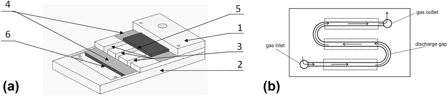
A new reactor was constructed to modify the polymer tubes’ external surfaces in the atmosphere of numerous gases (Fig. 1).
Reactor for the modification of the tubes. (a) 1—top cover, 2—bottom cover, 3—discharge gap, 4—dielectric barrier, 5—high-voltage electrode, and 6—grounded electrode. (b) Polycarbonate plate with a cut out discharge gap and labeled direction of gas flow; locations of measuring contact angles are marked by a dashed line.

The gas flow was constant through the discharge gap. The reactor operated in the horizontal position and had two dielectric barriers. The dimensions of the discharge gap were 3 × 3 mm. High-voltage and grounded electrodes were made of stainless steel.
The gas flow rate supplied to the reactor was regulated by mass flow controllers. The overall gas flow rate of air or argon and carbon dioxide or hydrogen was 20 NL/h. The gas was introduced to the front part of the reactor and passed through the gap to the gas outlet. The direction of the gas flow in the reactor is indicated by arrows in Fig. 1(b). Limitation of discharge space reduced the energy consumption and increased energy density in the discharge gap.
The 2 mm diameter tubes, used in the study, were made by Balton, Poland. The temperatures of softening and melting of the tubes were 80 and 170–200 °C, respectively. This kind of tubes is used for manufacturing of disposable surgical instruments, i.e., catheters. In the experiments, a fresh PE tube was placed in the discharge gap, in which the DBD was generated. The plasma reactor did not produce an additional discharge on the surface except in the dielectric gap. The length of the modified tube used in the measurements was 8 cm. Three tube sections were modified in every experiment. On two of them contact angle measurements were conducted, one for water and one for diiodomethane. More than four drops were placed on every sample. Contact angles were measured on both sides of the drops. For surface energy calculation, an average of the results was taken. The third one was used for the FTIR analysis. The location of the tube in the straight parts of the reactor did not affect the modification.
The reactor was supplied with alternating current of frequency 6.5 kHz and voltage of approx. 9 kV. The current–voltage characteristics were measured with a Tektronix DPO3034 oscilloscope with a P6015A voltage probe and a TCP0030 current probe (Tektronix Inc., Beaverton, Oregon). The discharge power was calculated using voltage and current waveforms in accordance with Eq. (1). The discharge power was 10 ± 1 W and it was constant during experiments.Reference Borcia, Anderson and Brown16
 $$P = {1 \over T}\int_t^{t + T} {U\left( t \right) \times I\left( t \right){\rm{d}}t} \quad .$$
At the inlet of the reactor, the temperature of the gas and samples was 25 °C and it did not change significantly during the experiments. At discharge power close to 10–11 W, it was in the range of 25–30 °C. Our previous experiments conducted at discharge power 60 W indicated that the temperature during modification increased above the softening temperature, and in this condition, the sample of the tube was damaged.
III. RESULTS AND DISCUSSION
Measurements were performed in synthetic air, argon, hydrogen, carbon dioxide, and in four gaseous mixtures: air + H2, air + CO2, Ar + H2, and Ar + CO2. Air, argon, hydrogen, and carbon dioxide have already been used for polymer surface modification. However, mixtures of those gases have not been often studied. Concentrations of the added gas (H2 or CO2) were 5, 10, 15, 25, and 50%. The contact angle of water and diiodomethane was measured for a fresh sample and after the modification. The contact angle was measured at the straight sections of the modified tube (Fig. 2) with the goniometric method.
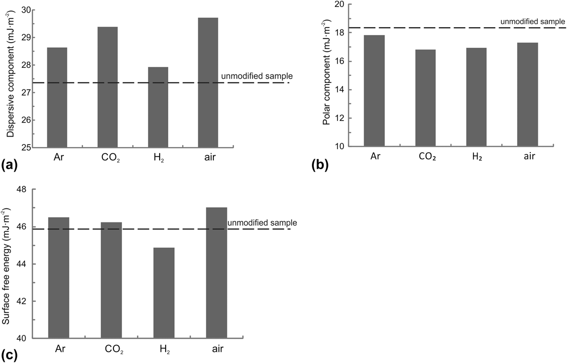
Influence of the gas on composition: (a) dispersive component, (b) polar component, and (c) SFE.

The SFE was calculated using the Owens–Wendt method,Reference Moraczewski, Stepczyńska, Malinowski, Rytlewski, Jagodziński and Żenkiewicz22 based on the assumption that the SFE is the sum of the dispersive  $\left( {\gamma _{\rm{s}}^{\rm{d}}} \right)$ and polar components
 $\left( {\gamma _{\rm{s}}^{\rm{p}}} \right)$.
A. Effect of the carrier gas on SFE and its components
The effect of the pure carrier gas on the values of dispersive and polar components and SFE was investigated (Fig. 2). The dashed line indicates the value for the unmodified sample.
First, the tests were made in pure gases. The values of the dispersive component of the modified sample increased by approx. 0.5–2.5 mJ/m2 compared to the unmodified one. The highest values were obtained for the gas mixture of air and CO2; 29.5 mJ/m2 and 29.3 mJ/m2, respectively [Fig. 2(a)]. The value of polar component obtained during modification in pure gases decreased by approx. 0.5–1 mJ/m2 compared to that of the unmodified tube’s surface. The values of the polar component were in the range of 17–18 mJ/m2 [Fig. 2(b)]. The SFE of samples modified in Ar, CO2, and air increased, whereas that for the one modified in H2 decreased [Fig. 2(c)].
It was observed that the carrier gas had a significant influence on the values of dispersive and polar components and SFE. Ar, CO2, and air had a favorable influence on the efficiency of the modification of the PE tube surface. The highest value of SFE was obtained using Ar and air. Therefore in the subsequent experiments, these gases were used in mixtures with hydrogen or carbon dioxide.
B. Effect of gas composition
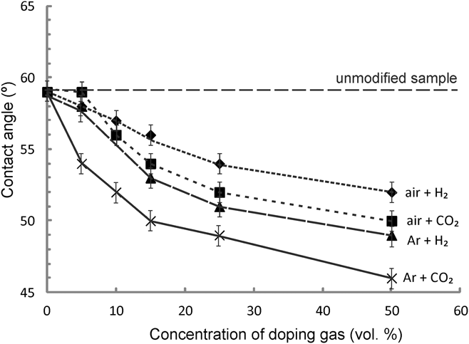
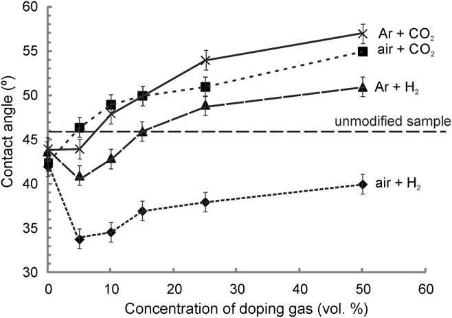
The effect of the composition of the mixture of gases on the values of the water contact angle (Fig. 3) and the diiodomethane contact angle was investigated (Fig. 4). The dashed line indicates the value for the unmodified sample.
Influence of the concentration of the doping gas on the water contact angle.

Dependence of the concentration of doping gas on the diiodomethane contact angle.

As can be seen in Fig. 3, the water contact angle decreased with increasing concentration of H2 or CO2. The smallest decrease was observed for the mixture of air and H2 (from 59° to 52°), whereas the largest reduction of the water contact angle was obtained for the mixture of argon and CO2 (from 59° to 46°). Smaller contact angles for the entire range of concentrations of the added gas (CO2 and H2) were obtained when the carrier gas was Ar. It was concluded that a greater amount of active species was generated in a discharge in argon than in air. It was also noticed that the water contact angle measured after modification with the mixture of CO2 reached lower values than after modification with H2 (Fig. 3). The doping of argon or air with hydrogen or carbon dioxide had a positive effect on the values of the contact angles of the modified PE surface.
Figure 4 depicts the effect of the doping gas concentration on the values of the diiodomethane contact angle. An increase in the contact angle was noted in most gas compositions. However, the use of 5 vol% hydrogen as the doping gas caused a significant decrease in the diiodomethane contact angle. The values of the contact angle for the mixture of air and H2 were lower than those for the unmodified sample for all studied concentrations. By contrast, the addition of CO2 resulted in higher contact angles, for concentrations of CO2 higher than 10 vol%, than in the case of the unmodified tube. The highest increase of the diiodomethane contact angles was reached when the mixture of argon and CO2 was used. The best hydrophilic properties of the PE tubes’ surface were obtained in the atmosphere of argon and CO2 and the lowest for the mixture of air and H2 (Fig. 4).
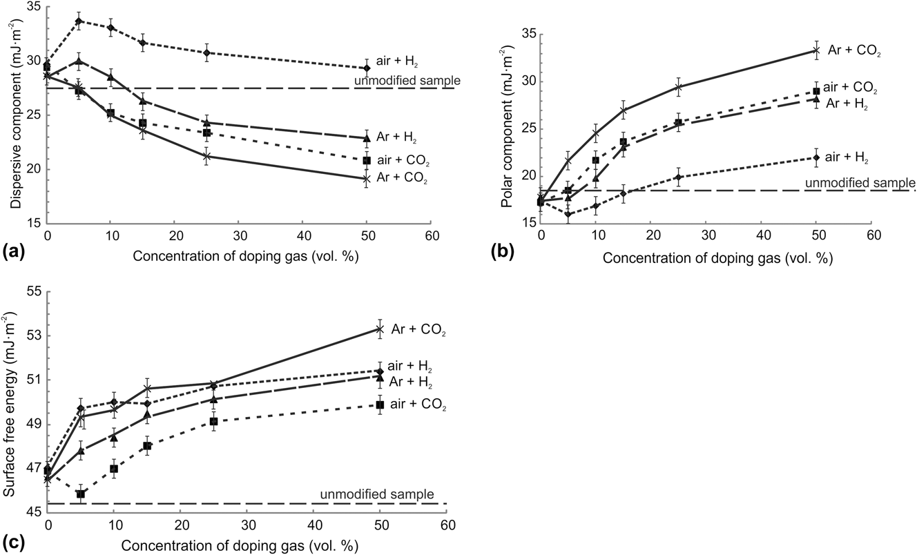
The values of the dispersive and polar components and SFE (Fig. 5) were calculated based on contact angle measurements.
Effect of doping gas concentration on (a) dispersive component, (b) polar component, and (c) SFE.

The value of the dispersive component was decreased and the value of the polar component was increased with increasing concentration of the doping gas for all studied gas mixtures. The biggest differences of polar and dispersive components compared to the unmodified sample were obtained using the mixture containing Ar + CO2 [Figs. 5(a) and 5(b)]. The lowest value of the dispersive component (19.2 mJ/m2) and the highest value of the polar component (33.4 mJ/m2) were observed after the modification in 50 vol% of argon and 50 vol% of CO2. Gas containing air and hydrogen had the smallest influence on the polar and dispersive components in the studied range of the doping gas concentrations. The hydrogen present in the gas mixture had a negative impact on the modification of the surface. The values of the polar component in H2 + Ar were lower than the values obtained in the gas containing CO2, but the dispersive component was higher. It resulted in a decrease of hydrophilicity of the tube’s surface.
Plasma modification of the PE tube’s surface resulted in an increase in the SFE in all experiments. The highest SFE, i.e., 52.5 mJ/m2, was obtained for 50 vol% Ar + 50 vol% CO2. A high value of the SFE (51.4 mJ/m2) was also obtained for air + H2, but this value was associated with a high value of the dispersive component, which did not affect the increase in the hydrophilicity of the surface. The lowest increase of the SFE was observed for gas containing air and CO2 [Fig. 5(c)]. These results are consistent with the results for the one-component gas, in which the higher values of the SFE were obtained for the surface modified in air, argon, or CO2 than for the unmodified surface.
C. Determination of reproducibility and stability of modification of a tube’s surface
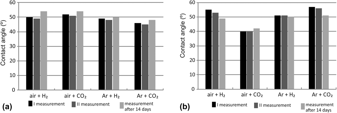
Two series of experiments were performed under the same conditions. Gas mixtures containing 50 vol% of air or Ar + 50 vol% of H2 or CO2 were used. The gas flow rate was 20 NL/h, with discharge 10 W. The stability of the modification of the PE tube surface was also examined. The contact angle of the samples was measured right after the modification and two weeks later [Figs. 6(a) and 6(b)]. To avoid the influence of the conditions of storage, the samples were stored two weeks in the air in controlled and constant humidity and temperature in an exsiccator, which was kept in the dark place.
Repeatability and stability of surface modification—measurement with: (a) distilled water and (b) diiodomethane.

As can be seen in Figs. 6(a) and 6(b), the modification of the PE tube surface in the plasma process is reproducible. The measured contact angles for the samples from the first and second series of measurements had the same or very similar values. Differences of contact angles did not exceed 1°, which is in the range of the measurement error. The same relations were observed for both measuring liquids.
However, the modification of the PE tube surface is not permanent. The values of contact angles measured 14 days after the modification were different from those measured immediately after modification. Water contact angles increased by two to five degrees, and diiodomethane contact angles decreased by one to five degrees. These changes of the contact angles are unfavorable because it causes a decrease in the hydrophilic properties of the surface of the samples.
D. Study of the chemical composition of the modified surface
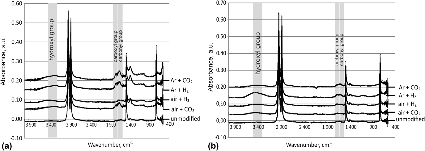
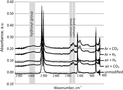
Spectra of the modified PE tubes were obtained using the ATR-FTIR to investigate the chemical composition of the surface (Fig. 7). A Nicolet 6700 spectrometer (Thermo Fisher Scientific, Madison, Wisconsin) with Specac Quest ATR single reflection (Specac Ltd., Orpington, United Kingdom) was used. Spectra were analyzed immediately after modification and 14 days after the modification to observe the changes of the surface in time.
FTIR spectra of samples obtained: (a) immediately after the modification and unmodified and (b) 14 days after the modification and unmodified.

In the FTIR spectra, three kinds of functional groups were detected: hydroxyl (3300–3400 cm−1), carbonyl (1600–1650 cm−1), and carboxyl (1650–1700 cm−1) groups. These groups may be responsible for the increase of the polar component of the SFE.Reference Abourayana, Milosavljevic, Dobbyn and Dowling32 The most intensive peak in the hydroxyl group band region was observed for Ar-containing gas mixtures. It could be the effect of the reaction of the material or its components, such as lubricants or plasticizers, with hydrogen or CO2 activated by the excited Ar species. Groups containing C–O or C=O bonds were not formed when air + H2 was used. When the doping gas was CO2, it was noticed that there is a significant amount of carbonyl and carboxyl groups formed on the samples’ surface. However, the presence of hydroxyl groups on the surface [Fig. 7(a)] was also detected.
Spectra of the samples tested after 14 days differ significantly from those obtained immediately after the modification. The peaks from hydroxyl, carboxyl, and carbonyl groups are less visible and smaller than in the spectra of the freshly modified samples. It suggests that the partial loss of the hydrophilic properties of the investigated tubes may be related to the disappearance of the hydroxyl and carbonyl groups on the surface of the samples [Fig. 7(b)].
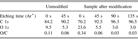
A complementary analysis of the surface groups with XPS was conducted. A K-Alpha™ XPS from Thermo Scientific™ (Thermo Fisher Scientific, Madison, Wisconsin) was used. The survey spectra, as well as detailed spectra of the O 1s and C 1s regions, were collected before the surface was etched and after 45, 90, and 135 s of Ar sputtering. The pass energy was 100 eV and 50 eV for the survey and detailed spectra, respectively. The relative at.% of oxygen and carbon, as well as the O/C ratios obtained from the XPS results, is presented in Table I.
Surface atomic concentration [%] of C and O as determined by XPS analysis.

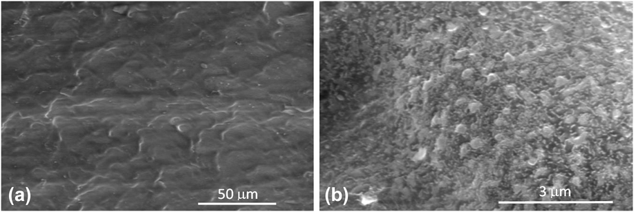
The obtained results confirm the limited presence of oxygen in the structure of the tube before the modification. However, after the plasma modification, the concentration of oxygen on the surface increased three times (Table I). Thus, the obtained values of free surface energy and polar component after modification are consistent with the results of the XPS and FTIR analysis. New polar groups introduced on the PE surface increased its polarity. Hydroxyl, carbonyl, and carboxyl groups were responsible for this effect. The higher polarity of the surface facilitates the wetting with polar liquids.Reference Van Deynse, Morent, Leys and De Geyter33 The visual effect of this phenomenon was the lower contact angle for polar liquids, i.e., water.Reference Hetemi and Pinson34 The new functional groups, introduced on the PE surface, also increased adhesion of the surface.Reference Mittal35 In industrial application, it improved bonding of the lubricant material with the modified layer. The experiments made in Balton’s laboratory confirmed the positive effect of the plasma treatment on adhesion of the outer layer of lubricant substances. It is especially important when the material is used for the production of disposable surgical instruments. SEM analysis showed uniform and continuous surfaces without local melting or puncture (Fig. 8).
SEM figures of the modified surface with a magnification of (a) 2000 and (b) 50,000 times. Gas composition of modification: 50 vol% of argon and 50 vol% of CO2.

IV. CONCLUSIONS
The experiments showed that the optimal gas mixture for DBD-plasma modification of PE tubes was the mixture of argon and CO2 containing 50 vol% Ar + 50 vol% CO2. The SFE of the most effectively modified sample was 53.4 mJ/m2 and the result is approx. 17% higher than that of the unmodified sample. It was concluded that the wettability of the PE tube surface was greatly improved by the plasma modification. Moreover, as the SEM images show, the surface was not damaged by the modification.
The reproducibility of the modification results was very good. The deviation did not exceed the measurement error. However, the stability of modification was quite low, which limits the use of the tubes. The ATR–FTIR investigation of the surface of modified tubes a few days after the modification showed a significant reduction of functional groups responsible for the increase of the wettability of the surface of the modified tubes.
Based on the results of the experiments, the following can be concluded:
(1) DBD is the effective method for modification of PE tube surfaces;
(2) DBD carrier gas composition has an important influence on plastic tube’s surface modification;
(3) The best wettability of the PE tubes’ surface (SFE 53.4 mJ/m2) was obtained with the gas mixture containing 50 vol% Ar and 50 vol% CO2.
ACKNOWLEDGMENTS
This work was supported by Warsaw University of Technology. The authors would like to thank Emil Płowiecki and Leszek Hurkała from Balton sp. z o. o. for providing the material for research. The authors would like to express their gratitude to Ilya Gourvich from the Center for Nanostructure Imaging (CNI) at the University of Toronto for performing the SEM-EDX measurements. We would also like to thank Ewa Iwanek for carrying out XPS studies and analyzing the results, as well as the Ontario Center for the Characterization of Advanced Materials (OCCAM) for enabling us to use the equipment needed to perform the XPS measurements.