Introduction
Improving comprehensive mechanical properties is always a central objective of materials research. However, traditional approaches for strengthening materials usually compromise their ductility. Regarding to metallic materials, benefit from the grain boundary (GB) strengthening effect, grain refinement can increase the amount of GBs and further enhance the strength of metals. This is just the so-called Hall–Petch effect [Reference Hall1, Reference Petch2]. Consequently, nanocrystalline metals attracted extensive investigations [Reference Kumar, Suresh and Van Swygenhoven3, Reference Meyers, Mishra and Benson4, Reference Dao, Lu, Asaro, De Hosson and Ma5, Reference Zhu, Bushby and Dunstan6, Reference Lu, Lu and Suresh7, Reference Zhu and Li8]. Unfortunately, the ductility of nanocrystalline metals with high strength becomes very limited, i.e., the strength–ductility trade-off dilemma still cannot be evaded. The low ductility of nanocrystalline materials is mainly derived from the deformation and premature failure in interfaces within the material; thus, this shortcoming could be overcome by tuning the interfacial structures or properties. Such effort is usually called as interfacial engineering [Reference Lu, Lu and Suresh7].
Among all possible boundary structures, twin boundary (TB) stands out for its capability to enhance strength and retain ductility of crystalline metals [Reference Lu, Lu and Suresh7, Reference Zhu, Liao and Wu9, Reference Zhu and Gao10, Reference Sun, He and Lu11, Reference Lu, Shen, Chen, Qian and Lu12, Reference Shen, Lu, Lu, Jin and Lu13, Reference Shan, Lu, Minor, Stach and Mao14, Reference Lu, Chen, Huang and Lu15, Reference Lu, Dao, Zhu and Li16, Reference Lu, Zhu, Shen, Dao, Lu and Suresh17, Reference You, Lu and Lu18]. TBs play a strengthening role like other kinds of boundary structures, and they interact with dislocations; thus, various defects, such as full dislocation, Shockley partial dislocation, Lomer–Cottrell locking, and stacking fault, are generated at the TBs. Consequently, the movement of dislocations is impeded, and the strength of metals is enhanced. Meanwhile, reaction would occur between dislocations and TBs, i.e., dislocations will be absorbed on TBs, and then the stress concentration status derived from dislocation pile-up could be released. Eventually, the material gains considerable deformation capability. Hence, TBs could further enhance the ductility of nanocrystalline metals. Recently, a new kind of advanced microstructure, hierarchical nanotwin (HNT), is developed. The number of TBs further increases significantly in the hierarchically nanotwinned metals, and relatively good ductility can be retained in this kind of material while its strength is enhanced considerably [Reference Sun, He and Lu11, Reference Qu, An, Yang, Huang, Yang, Zang, Wang, Wu and Zhang19, Reference Tao and Lu20, Reference Liddicoat, Liao, Zhao, Zhu, Murashkin, Lavernia, Valiev and Ringer21, Reference Müllner and King22, Reference Cong, Zhang, Esling, Wang, Lecomte, Zhao and Zuo23, Reference Kou, Lu and Li24, Reference Wei, Li, Zhu, Liu, Lei, Wang, Wu, Mi, Liu, Wang and Gao25, Reference Shin, Yin, Li, Lee, Moon, Jeong, Kwon, Yoo, Kim, Zhang, Gao and Oh26, Reference Zhang, Sheng, Wang, Gludovatz, Zhang, George, Yu, Mao and Ritchie27, Reference Koyama, Zhang, Wang, Ponge, Raabe, Tsuzaki, Noguchi and Tasan28, Reference Liu, Sun, Zhu, Liu, Lu and Lu29]. Especially, as high as five-order HNTs were fabricated successfully recently, and related mechanical experiments demonstrated that the strength of the high-order hierarchically nanotwinned metal is enhanced without sacrificing its ductility compared with the same kind of metals without HNTs or with low-order HNTs [Reference Liu, Sun, Zhu, Liu, Lu and Lu29], i.e., the comprehensive mechanical properties are improved considerably.
At the same time, related experimental investigations also demonstrated that the strengthening effect of TBs depends on the twin spacing. Along with the reduction in twin spacing, the yield strength of nanotwinned copper increases gradually first and reaches a maximum value at a critical spacing and then the strength transits into a descend tendency with further decrease in the twin spacing; besides, the ductility of materials also changes with the variation of twin spacing [Reference Lu, Shen, Chen, Qian and Lu12, Reference Shen, Lu, Lu, Jin and Lu13, Reference Shan, Lu, Minor, Stach and Mao14, Reference Lu, Chen, Huang and Lu15, Reference Lu, Dao, Zhu and Li16, Reference Lu, Zhu, Shen, Dao, Lu and Suresh17]. This implies that TBs play an important role in the mechanical properties of nanotwinned metals. At present, related research on the influence of TBs is mainly based on the experimental investigations on the microstructure and the molecular dynamic (MD) simulations [Reference Zhu and Gao10, Reference Sun, He and Lu11], wherein the early MD simulation mainly focused on the nanotwinned metals [Reference Zhu, Li, Samanta, Kim and Suresh30, Reference Jin, Gumbsch, Albe, Ma, Lu, Gleiter and Hahn31, Reference Shabib and Miller32, Reference Li, Wei, Lu, Lu and Gao33, Reference Wei34, Reference Zhou, Qu and Yang35, Reference Zhou, Li, Qu, Yang and Gao36, Reference Sun, He and Lu37, Reference Yuan and Wu38], and recently, it also concerns the hierarchically nanotwinned metals [Reference Yuan and Wu39, Reference Yuan and Wu40, Reference Yuan, Chen, Jiang and Wu41, Reference Yuan and Wu42, Reference Sun, He, Zhu and Lu43].
Related investigations demonstrated that interactions between TBs and dislocations are the determining factor for the macroscopic mechanical properties of nanotwinned metals, and the corresponding interactions are complicated, which depend on various factors, e.g., TBs and the activated dislocation slip systems [Reference Zhu and Gao10, Reference Sun, He and Lu11, Reference Lu, Shen, Chen, Qian and Lu12, Reference Shen, Lu, Lu, Jin and Lu13, Reference Shan, Lu, Minor, Stach and Mao14, Reference Lu, Chen, Huang and Lu15, Reference Lu, Dao, Zhu and Li16, Reference Lu, Zhu, Shen, Dao, Lu and Suresh17, Reference You, Lu and Lu18, Reference Zhu, Li, Samanta, Kim and Suresh30, Reference Jin, Gumbsch, Albe, Ma, Lu, Gleiter and Hahn31, Reference Shabib and Miller32, Reference Li, Wei, Lu, Lu and Gao33, Reference Wei34, Reference Zhou, Qu and Yang35, Reference Zhou, Li, Qu, Yang and Gao36, Reference Sun, He and Lu37, Reference Yuan and Wu38, Reference Yuan and Wu39, Reference Yuan and Wu40, Reference Yuan, Chen, Jiang and Wu41, Reference Yuan and Wu42, Reference Sun, He, Zhu and Lu43, Reference Liao, Zhou, Lavernia, Srinivasan, Baskes, He and Zhu44, Reference Ni, Wang, Liao, Figueiredo, Li, Ringer, Langdon and Zhu45, Reference Zhu, Wu, Liao, Narayan, Mathaudhu and Kecskes46, Reference Zhu, Wu, Liao, Narayan, Kecskes and Mathaudhu47, Reference Wang and Sui48, Reference Lu, Du, Lu and Ye49, Reference Chassagne, Legros and Rodney50, Reference Yu, Bufford, Sun, Liu, Wang, Kirk, Li and Zhang51, Reference Wang, Lu, Kong, Xiao, Sha, Sun, Zhang and Han52]. In special, the geometrical characteristics of nanotwin (NT; e.g., twin spacing, twin length, and twin orientation) and the external loading condition will also affect the interactions between TBs and dislocations. Correspondingly, there exist several kinds of dislocation-mediated deformation mechanisms in nanotwinned metals, e.g., full dislocation pile-up against and slip transfer across TBs, Shockley partial dislocation gliding on TBs leading to TB migration, and threading dislocation slip confined by neighboring TBs. Besides, different deformation mechanisms are switchable, and they are related to the twin spacing, for instance, the movement of full dislocations will dominate the deformation in the thick twin lamellae; whereas within the thin twin lamellae, the deformation will be governed by the gliding of Shockley partial dislocations on TBs.
Compared with experimental investigations and numerical simulations, the theoretical modeling work for nanotwinned metals is still rare. Because the mechanism for the interactions between dislocations and TBs is still poorly understood, the development of theoretical models to completely describe the deformation and failure behaviors of materials is challenging. Nevertheless, theoretical modeling is of great importance. It is useful for precise understanding of physical mechanisms, effectively predicting mechanical behaviors, and conveniently acting as guidance for the material design. There have been some effective attempts, and the proposed models are mainly modified crystal plasticity models, which take the effect of NTs into consideration. The early models mainly concerned nanotwinned metals [Reference Asaro and Suresh53, Reference Dao, Lu, Shen and Suresh54, Reference Jerusalem, Dao, Suresh and Radovitzky55, Reference Mirkhani and Joshi56, Reference Zhang, Romanov and Aifantis57, Reference Zhu, Ruan, Li, Dao, Gao and Lu58], and recently, they are further extended to describe the mechanical behaviors of hierarchically nanotwinned metals [Reference Zhu, Kou and Lu59, Reference Zhu, Qu, Guo and Lu60, Reference Li, Ni, Soh and Wu61]. Among these theoretical modeling, Zhu et al. [Reference Zhu, Ruan, Li, Dao, Gao and Lu58, Reference Zhu, Kou and Lu59, Reference Zhu, Qu, Guo and Lu60] developed a mechanism-based plasticity model, which could predict relatively well the twin spacing and grain size effects on the mechanical properties.
As mentioned above, metals with high-order HNTs (up to five orders) [Reference Liu, Sun, Zhu, Liu, Lu and Lu29] can be fabricated successfully now, and the corresponding materials have better comprehensive mechanical performances. In the present paper, we further develop related mechanism-based plasticity models for the high-order hierarchically nanotwinned metals. Especially, the explicit analytical expressions for the flow stress and the failure strain with various parameters are deduced to clearly present the influences of these factors. Besides, the mechanical properties are investigated systemically based on the corresponding models, and the effects of twin spacing and grain size on the strength and ductility are discussed in detail. Finally, related optimization design method for the microstructure of materials is suggested to achieve the simultaneous high strength and high ductility, which is of great significance for practical applications.
Theoretical model
Flow stress
The flow stress can usually be expressed as Taylor-type relationship in terms of the dislocation density. The corresponding expression for hierarchically nanotwinned metals is as follow:
 $${\sigma _{{\rm{flow}}}} = M\alpha \mu b\sqrt {{\rho _{\rm{I}}} + {\rho _{{\rm{GB}}}} + {\rho _{{\rm{TB}}}}} \quad ,$$
where M is the Taylor factor, α is the Taylor empirical constant, μ is the shear modulus, b is the magnitude of Burgers vector, ρI is the dislocation density in the interior crystal, ρGB is the dislocation density in the grain boundary dislocation pile-up zone (GBDPZ), and ρTB is the total dislocation density in the twin boundary dislocation pile-up zone (TBDPZ) in all layers of twin lamellae.
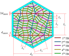
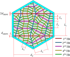
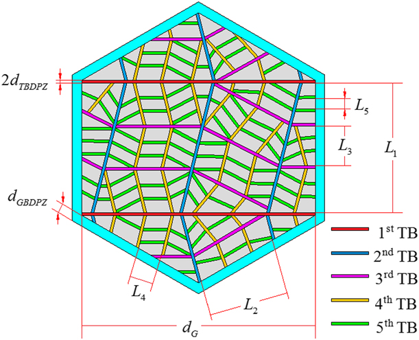
It is known from Eq. (1) that dislocation densities in the three regions play an important role for the flow stress, and they will be analyzed in detail in the following. For convenience of theoretical modeling, all dislocation densities are defined in a unit cell of a grain, i.e., the flow stress σflow depends on the total dislocation densities within the whole cell. To understand the HNT structure more easily, Fig. 1 shows the sketch of unit cell of a grain with high-order HNTs (five-order HNTs displayed). In the schematic drawing in Fig. 1, d G is the size of unit cell, considered to be the grain size; d GBDPZ is the thickness of the GBDPZ; d TBDPZ is the thickness of the TBDPZ; and L i is the twin spacing of the ith layer of twin lamellae.
Sketch of unit cell of a grain with high-order HNTs.
Dislocation density in crystal interior
For submicron grains, the plastic deformation is dominated by the intragrain dislocation–mediated interaction. The amount of dislocations in the crystal interior varies with the plastic strain and is governed by the competition between accumulation and annihilation processes through dynamic recovery. The evolution of dislocation density in crystal interior with the plastic strain εp can be described by the Kocks–Mecking model [Reference Kocks and Mecking62]:
 $${{\partial {\rho _{\rm{I}}}} \over {\partial {\varepsilon ^{\rm{p}}}}} = M\left( {{K \over {{d_{\rm{G}}}}} + {K_1}\sqrt {{\rho _{\rm{I}}}} - {K_2}{\rho _{\rm{I}}}} \right)\quad ,$$
where K = 1/b; K 1 = ψ/b, in which ψ is a proportionality factor; and  ${K_2} = {K_{2 - 0}}{\left( {{{{{\dot{\varepsilon }}^{\rm{p}}}} / {{{\dot{\varepsilon }}_0}}}} \right)^{{{ - 1} / n}}}$, wherein K 2–0 is a material constant,
 ${\dot{\varepsilon }_0}$ is the referenced strain rate, and n is inversely proportional to the temperature.
The first two terms on the right-hand side of Eq. (2) account for dislocation storage, and the coefficients, K and K 1, are related to the mean free path of mobile dislocations. Comparatively, the third term is associated with the annihilation of dislocations during dynamic recovery, and the coefficient K 2 depends on both the strain rate and temperature. There have been some investigations on the influences of strain rate and temperature [Reference Capolungo, Cherkaoui and Qu63, Reference Gao and Zhang64, Reference Yasnikov, Estrin and Vinogradov65]. In the present work, we mainly focus on the size effect on the strength and ductility of materials, i.e., the influences of twin spacing and grain size. For simplicity of theoretical model, the strain rate and temperature dependence are assumed as  ${{{{\dot{\varepsilon }}^{\rm{p}}}} / {{{\dot{\varepsilon }}_0}}} = 1$ and then K 2 = K 2–0. Consequently, the relationship between ρI and εp in Eq. (2) becomes:
 $${{\partial {\rho _{\rm{I}}}} \over {\partial {\varepsilon ^{\rm{p}}}}} = M\left( {{1 \over {b{d_{\rm{G}}}}} + {\psi \over b}\sqrt {{\rho _{\rm{I}}}} - {K_{2 - 0}}{\rho _{\rm{I}}}} \right)\quad .$$
There is no analytical solution in Eq. (3), and alternatively it needs to be solved by numerical iterative method. However, the numerical iterative solution will lead to some inconvenience to the practical application, and it is necessary to make some reasonable simplification under the assurance of correct prediction to find the analytical relationship of ρI to εp. Suppose, ρI could be divided into two parts, ρI1 and ρI2 and their evolutions with εp can be expressed as follows:
 $${\rho _{\rm{I}}} = {\rho _{{\rm{I1}}}} + {\rho _{{\rm{I2}}}}\quad ,$$
 $${{\partial {\rho _{{\rm{I1}}}}} \over {\partial {\varepsilon ^{\rm{p}}}}} = {M \over b}{1 \over {{d_{\rm{G}}}}}\quad ,$$
 $${{\partial {\rho _{{\rm{I2}}}}} \over {\partial {\varepsilon ^{\rm{p}}}}} = M\left( {{\psi \over b}\sqrt {{\rho _{\rm{I}}}} - {K_{2 - 0}}{\rho _{\rm{I}}}} \right) \approx M\left( {{\psi \over b}\sqrt {{\rho _{{\rm{I2}}}}} - {K_{2 - 0}}{\rho _{{\rm{I2}}}}} \right)\quad .$$
The approximation in Eq. (4c) could be satisfied well under the condition of  $\left( {{{\psi \sqrt {{\rho _{\rm{I}}}} } / b} - {K_{2 - 0}}{\rho _{\rm{I}}}} \right) \gg {1 / {\left( {b{d_{\rm{G}}}} \right)}}$ [Reference Yasnikov, Estrin and Vinogradov65]. Regarding the practical material, the grain is relatively coarse, i.e., the grain size d G is large enough and d G ≫ b (see parameters in Table I), thus such a condition is usually met. Consequently, the analytical relationship between ρI1 and εp can be obtained from Eq. (4b):
 $${\rho _{{\rm{I1}}}} = {M \over {b{d_{\rm{G}}}}}{\varepsilon ^{\rm{p}}}\quad .$$
Material parameters, from Refs. Reference Lu, Shen, Chen, Qian and Lu12–Reference You, Lu and Lu18 and Reference Zhu, Ruan, Li, Dao, Gao and Lu58–Reference Zhu, Qu, Guo and Lu60.

In the following, the evolution of ρI2 will be deduced based on Eq. (4c). Set a variable substitution as  $\sqrt {{\rho _{{\rm{I2}}}}} = x$, thus ρI2 = x 2, then the differential expression in Eq. (4c) can be transformed into the integral form:
 $$\int {{1 \over { - M{K_{2 - 0}} \cdot x + M{\psi \over b}}}{\rm{d}}x} = \int {{1 \over 2}{\rm{d}}{\varepsilon ^{\rm{p}}}} \quad .$$
An equation of |−MK 2−0·x + Mψ/b| = C 0 exp(−MK 2−0εp/2) can be obtained from Eq. (6), wherein C 0 is a material constant with the same dimension as the term 1/b, and it is associated with the mean free path of dislocations during the thermally activated dynamic recovery process. Considering the practical parameters, we have −MK 2−0·x + Mψ/b > 0 (see Table I), then the expression of parameter x can be represented as follows:
 $$x = {{M{\psi \over b} - {C_0}\exp \left( {{{ - M{K_{2 - 0}}} \over 2}{\varepsilon ^{\rm{p}}}} \right)} \over {M{K_{2 - 0}}}}\quad .$$
As mentioned above, dislocations in the crystal interior increase gradually with the plastic strain. When there is no plastic strain (εp = 0) in the initial stage, it can be assumed that the dislocation density takes the value of ρI2 = 0 and correspondingly  $x = \sqrt {{\rho _{{\rm{I2}}}}} = 0$. By substituting the values of εp = 0 and x = 0 back into Eq. (7), the expression of the material constant C 0 can be calculated as C 0 = Mψ/b. Consequently, the analytical expression of ρI2 with εp can be obtained as follows:
 $${\rho _{{\rm{I2}}}} = {\left( {{\psi \over {{K_{2 - 0}}}}} \right)^2}{1 \over {{b^2}}}{\left[ {1 - \exp \left( {{{ - M{K_{2 - 0}}} \over 2}{\varepsilon ^{\rm{p}}}} \right)} \right]^2}\quad .$$
Substituting Eqs. (5) and (8) into Eq. (4a) leads to the evolution of ρI with εp as follows:
 $$\eqalign{{\rho _{\rm{I}}} = {\rho _{{\rm{I1}}}} + {\rho _{{\rm{I2}}}} = {M \over {b{d_{\rm{G}}}}}{\varepsilon ^{\rm{p}}} + {\left( {{\psi \over {{K_{2 - 0}}}}} \right)^2}\cr{1 \over {{b^2}}}{\left[ {1 - \exp \left( {{{ - M{K_{2 - 0}}} \over 2}{\varepsilon ^{\rm{p}}}} \right)} \right]^2}\quad .$$
Equation (9) shows that ρI will increase gradually with εp, and this represents the strain hardening effect. Besides, ρI will also increase with the reduction in d G. However, it does not display a direct proportional or inverse proportional relationship to these factors.
Dislocation density in GBDPZ
The definition of dislocation density in the GBDPZ is as follows [Reference Zhu, Ruan, Li, Dao, Gao and Lu58]:
 $${\rho _{{\rm{GB}}}} = {{{\lambda _{{\rm{GB}}}}} \over {{V_{{\rm{Cell}}}}}}{n^{{\rm{GB}}}}\quad ,$$
where V Cell is the volume of unit cell, λGB is the average length of dislocation loops in the GBDPZ, and n GB is the number of dislocations around the GB.
Integrated with the sketch in Fig. 1, the volume of unit cell is V Cell = πd G3/6, and the average length of dislocation loops can be assumed to be λGB = πd G [Reference Zhu, Ruan, Li, Dao, Gao and Lu58]. Substituting these expressions into Eq. (10) yields the analytical expression of ρGB:
 $${\rho _{{\rm{GB}}}} = {{\pi {d_{\rm{G}}}} \over {{{\pi {d_{\rm{G}}}^3} / 6}}} = {{6{n^{{\rm{GB}}}}} \over {{d_{\rm{G}}}^2}}\quad .$$
It shows that ρGB is inversely proportional to d G2 and increases with the reduction in grain size.
Dislocation density in TBDPZ
Dislocations will pile up at TBs during the deformation process of nanotwinned metals, thus the geometrical mean strain gradient associated with dislocations within the TBDPZ increases gradually with the plastic strain. The local mean strain gradient created by dislocations in the TBDPZ can be defined as follows [Reference Zhu, Ruan, Li, Dao, Gao and Lu58, Reference Zhu, Kou and Lu59, Reference Zhu, Qu, Guo and Lu60]:
 $${\eta ^{{\rm{TB}}}} = {\phi ^{{\rm{TB}}}}{b \over {{d_{{\rm{GBDPZ}}}}{d_{\rm{G}}}}}\left( {n_{\rm{F}}^{{\rm{TB}}} + {{n_{\rm{P}}^{{\rm{TB}}}} \over {\sqrt 3 }}} \right)\quad ,$$
in which ϕTB is the geometric factor,  $n_{\rm{F}}^{{\rm{TB}}}$ is the number of full dislocations around TBs, and
 $n_{\rm{P}}^{{\rm{TB}}}$ is the number of partial dislocations stored in the TBDPZ.
Similar to the definition in Eq. (10), the partial dislocation density in the ith layer of twin lamellae can be defined as follows [Reference Zhu, Kou and Lu59, Reference Zhu, Qu, Guo and Lu60]:
 $${\rho _i}^{{\rm{part}}} = {{{\lambda _i}} \over {{V_i}}}n_{\rm{P}}^{{\rm{TB}}}\quad ,$$
where λi and V i are the average length of dislocation loops and the average volume in the ith layer of twin lamella. Integrated with the sketch in Fig. 1, the values of λi and V i can be obtained as follows:
 $$\left\{ \matrix{ {\lambda _1} = {d_{\rm{G}}} \hfill \cr {\lambda _i} = {L_{i - 1}},\;\left( {i > 1} \right) \hfill \cr} \right.\quad ,$$
 $$\left\{ \matrix{ {V_1} = {\pi \over 4}d_{\rm{G}}^2{L_1} \hfill \cr {V_i} = {d_{\rm{G}}}{L_i}{L_{i - 1}},\;(i > 1) \hfill \cr} \right.\quad .$$
Besides, as partial dislocations are almost all stored along TBs, the partial dislocation density in the twin lamellae can also be expressed with respect to the twin spacing:
 $${\rho _i}^{{\rm{part}}} = {{{\phi _0}} \over {{L_i}^2}}\quad ,$$
where ϕ0 is a geometrical factor.
Integrated with Eqs. (13)–(16), the number of partial dislocations in the TBDPZ can be obtained as follows:
 $$n_{\rm{P}}^{{\rm{TB}}} = {\phi _0}{{{V_i}} \over {{\lambda _i}{L_i}^2}}\quad .$$
Similarly, based on Fig. 1, the full dislocation density nearby TBs of the ith layer of twin lamellae can be defined as follows [Reference Zhu, Kou and Lu59, Reference Zhu, Qu, Guo and Lu60]:
 $${\rho _{{\rm{TB}} - i}} = {\chi _i}{{2{\lambda _i}} \over {{V_{{\rm{Cell}}}}}}n_{\rm{F}}^{{\rm{TB}}}\quad ,$$
in which χi = d G/L i is the twin density of the ith layer of twin lamellae.
By substituting Eqs. (12) and (17) into Eq. (18), ρTB−i can further be expressed as follows:
 $${\rho _{{\rm{TB}} - i}} = {{2{\chi _i}{\lambda _i}} \over {{V_{{\rm{Cell}}}}}}\left( {{1 \over {{\phi ^{{\rm{TB}}}}}}{{{d_{{\rm{TBDPZ}}}}{d_{\rm{G}}}} \over b}\eta _i^{{\rm{TB}}} - {{{\phi _0}} \over {\sqrt 3 }}{{{V_i}} \over {{\lambda _i}{L_i}^2}}} \right)\quad .$$
For the relatively large twin lamella, the local mean strain gradient can be written as a linear function of twin spacing, and the detailed expression of local mean strain gradient in the ith layer of twin lamellae,  $\eta _i^{{\rm{TB}}}$, is defined as follows [Reference Zhu, Ruan, Li, Dao, Gao and Lu58, Reference Zhu, Kou and Lu59, Reference Zhu, Qu, Guo and Lu60]:
 $$\eta _i^{{\rm{TB}}} = {\eta _1}{L_i} + {\eta _0}\quad ,$$
 $${\eta _1} = {\phi ^{{\rm{TB}}}}{N_0}{b \over {{d_{{\rm{TBDPZ}}}}{d_{\rm{G}}}^2}}\quad ,$$
 $${\eta _0} = {{{\phi ^{{\rm{TB}}}}} \over {\sqrt 3 }}n_{\rm{p}}^'{b \over {{d_{{\rm{TBDPZ}}}}{d_{\rm{G}}}}}\quad ,$$
where N 0 is the maximum number of full dislocations in the grain and  $n_{\rm{p}}^{\rm{'}}$ is the initial number of partial dislocations in the TBDPZ. It should be noted that both parameters are independent of the twin spacing.
Substituting Eq. (20) back into Eq. (19) yields:
 $${\rho _{{\rm{TB}} - i}} = {{2{\chi _i}{\lambda _i}} \over {{V_{{\rm{Cell}}}}}}\left( {{{{N_0}} \over {{d_{\rm{G}}}}}{L_i} + {{n_{\rm{p}}^{\rm{'}}} \over {\sqrt 3 }} - {{{\phi _0}} \over {\sqrt 3 }}{{{V_i}} \over {{\lambda _i}{L_i}^2}}} \right)\quad .$$
The first two terms on the right side of Eq. (21) are from the contribution of strain gradient along TBs; comparatively, the third term is related to the twinning partial dislocations.
By substituting Eqs. (14) and (15) back into Eq. (21), the full dislocation densities in every layer of twin lamellae are given as follows:
 $$\left\{ \matrix{ {\rho _{{\rm{TB}} - 1}} = {{12{N_0}} \over \pi }{1 \over {{d_{\rm{G}}}^2}} + {{12n_{\rm{p}}^{\rm{'}}} \over {\sqrt 3 \pi }}{1 \over {{d_{\rm{G}}}{L_1}}} - \sqrt 3 {\phi _0}{1 \over {{L_1}^2}} \hfill \cr {\rho _{{\rm{TB}} - i}} = {{12{N_0}} \over \pi }{{{L_{i - 1}}} \over {{d_{\rm{G}}}^3}} + {{12n_{\rm{p}}^{\rm{'}}} \over {\sqrt 3 \pi }}{{{L_{i - 1}}} \over {{d_{\rm{G}}}^2{L_i}}} - {{12{\phi _0}} \over {\sqrt 3 \pi }}{{{L_{i - 1}}} \over {{d_{\rm{G}}}{L_i}^2}},\;\left( {i > 1} \right) \hfill \cr} \right.\quad .$$
The total density of dislocations nearby TBs is the sum of that in each layer of twin lamellae, namely:
 $${\rho _{{\rm{TB}}}} = \sum\limits_{i = 1}^N {{\rho _{{\rm{TB}} - i}}} \quad ,$$
in which N is the order of hierarchical twin lamellae. It can be known from Eqs. (22) and (23) that ρTB also increases with the reduction in d G, but it does not display as a standard inverse proportional relationship.
Hence, the flow stress of hierarchically nanotwinned metals could be obtained by substituting Eqs. (9), (11), and (23) into Eq. (1). Especially, as Eqs. (9), (11), and (23) provide the analytical relationships of various dislocation densities to related parameters, the corresponding theoretical model gives the analytical expression of flow stress.
Ductility
During the plastic deformation, a great number of dislocations are prevented by TBs and GBs in the hierarchically nanotwinned metals, and dislocations will pile up nearby these boundaries. The pile-up of dislocations will lead to higher local stress, and it further generates stress concentration in these regions. Consequently, material failure will start in these areas with stress concentration. Hence, the stress-based failure criterion can be employed to evaluate the ductility of materials, and the criterion for the nanotwinned metal is proposed as follows [Reference Zhu, Ruan, Li, Dao, Gao and Lu58, Reference Zhu, Qu, Guo and Lu60]:
 $${}_{\rm{L}}{\tau _{{\rm{flow}}}} \ge {\tau _{{\rm{crit}}}}\quad ,$$
where  ${}_{\rm{L}}{\tau _{{\rm{flow}}}}$ is the local flow stress within the material and τcrit is the necessary stress for nucleating a dislocation. Equation (24) implies that the twin lamella will start to fail when the local flow stress exceeds the critical stress to nucleate dislocations.
Regarding hierarchically nanotwinned metals, the maximum local flow stress is usually arose in the areas bounded by TBs. Similar to the definition in Eq. (1), the local flow stress can be defined as follows [Reference Zhu, Qu, Guo and Lu60]:
 $${}_{\rm{L}}{\tau _{{\rm{flow}}}} = \alpha \mu b\sqrt {{\rho _{\rm{I}}} + {}_{\rm{L}}{\rho _{{\rm{TB}}}}} \quad ,$$
where  ${}_{\rm{L}}{\rho _{{\rm{TB}}}}$ is the total local dislocation density in the TBDPZ, i.e., the sum of the local dislocation density in the TBDPZ of the ith layer of twin lamellae, namely:
 $${}_{\rm{L}}{\rho _{{\rm{TB}}}} = \sum\limits_{i = 1}^N {{}_{\rm{L}}{\rho _{{\rm{TB}} - i}}} \quad .$$
Similar to the definition of ρTB−i in Eq. (18),  ${}_{\rm{L}}{\rho _{{\rm{TB}} - i}}$ is expressed as follows [Reference Zhu, Qu, Guo and Lu60]:
 $${}_{\rm{L}}{\rho _{{\rm{TB}} - i}} = {{2{\lambda _i}} \over {{V_i}}}n_{\rm{F}}^{{\rm{TB}}} = {{2{\lambda _i}} \over {{V_i}}}\left( {{N_0}{{{L_i}} \over {{d_{\rm{G}}}}} + {{n_{\rm{p}}^{\rm{'}}} \over {\sqrt 3 }}} \right) - {{2{\phi _0}} \over {\sqrt 3 }}{1 \over {{L_i}^2}}\quad .$$
Substitution of Eqs. (14) and (15) into Eq. (27) leads to the corresponding local dislocation densities as follows:
 $$\left\{ \matrix{ {}_{\rm{L}}{\rho _{{\rm{TB}} - 1}} = {4 \over \pi }2{N_0}{1 \over {{d_{\rm{G}}}^2}} + {4 \over \pi }{{2n_{\rm{p}}^{\rm{'}}} \over {\sqrt 3 }}{1 \over {{d_{\rm{G}}}{L_1}}} - {{2{\phi _0}} \over {\sqrt 3 }}{1 \over {{L_1}^2}} \hfill \cr {}_{\rm{L}}{\rho _{{\rm{TB}} - i}} = 2{N_0}{1 \over {{d_{\rm{G}}}^2}} + {{2n_{\rm{p}}^{\rm{'}}} \over {\sqrt 3 }}{1 \over {{d_{\rm{G}}}{L_i}}} - {{2{\phi _0}} \over {\sqrt 3 }}{1 \over {{L_i}^2}},\;\left( {i > 1} \right) \hfill \cr} \right.\quad .$$
By combining Eq. (9) with Eqs. (26)–(28) in Eq. (25), an analytical expression of the local flow stress can be obtained.
In the following, the critical stress τcrit will be analyzed. With consideration of the nucleation of a dislocation loop from stress concentration, Asaro and Suresh [Reference Asaro and Suresh53] proposed the expression of free energy of the expanding loop as:
 $$U = \Phi r\ln \left( {{r / {{r_0}}}} \right) - \Gamma \left( {{r^{{3 / 2}}} - {r_0}^{{{ - 3} / 2}}} \right) + {\pi \over 2}E\left( {{r^2} - {r_0}^2} \right)\quad ,$$
 $$\Phi = \mu {b_1}^2{{2 - \nu } \over {8\left( {1 - \nu } \right)}}\quad ,$$
 $$\Gamma = 1.4{\tau _{{\rm{crit}}}}{b_1}\sqrt {{\pi \over 2}{d^*}} \quad ,$$
where r is the radius of dislocation loop; r 0 is an inner cutoff radius; E is the energy per unit area of the loop, and it can be taken as the stacking fault energy; b 1 is the magnitude of Burgers vector, b 1 = b for the full dislocation and  ${b_1} = {b / {\sqrt 3 }}$ for the partial dislocation; and d* is a characteristic length, d* = d G for GBs and d* = L i for TBs.
The critical radius and the critical stress can be determined by calculating the first-order and second-order derivatives of Eq. (29):
 $$\eqalign{{{\partial U} \over {\partial r}} = \Phi \ln \left( {{r \over {{r_0}}}} \right) + \pi Er - {3 \over 2}\Gamma {r^{{1 \over 2}}} + \Phi = \Phi \ln r \cr+ \pi Er - {3 \over 2}\Gamma {r^{{1 \over 2}}} + \Phi \left( {1 - \ln {r_0}} \right) = 0\quad ,$$
 $${{{\partial ^2}U} \over {\partial {r^2}}} = \Phi {r^{ - 1}} - {3 \over 4}\Gamma {r^{ - {1 \over 2}}} + \pi E = 0\quad .$$
Equation (31) results in that:
 $$\pi Er - {3 \over 4}\Gamma \sqrt r + \Phi = 0\quad .$$
By defining  $\sqrt r = x$ and r = x 2 and substituting them into Eq. (32), the critical radius can be calculated as follows:
 $$\eqalign{{r_{{\rm{crit}}}} = {\left( {{{{{3\Gamma } / 4} \pm \sqrt {{{\left( {{{3\Gamma } / 4}} \right)}^2} - 4\pi \Phi E} } \over {2\pi E}}} \right)^2} \cr= {{{9 \over {32}}{\Gamma ^2} - \pi \Phi E \pm {3 \over 8}\Gamma \sqrt {{9 \over {16}}{\Gamma ^2} - 4\pi \Phi E} } \over {{\pi ^2}{E^2}}}\quad .$$
The critical stress τcrit can be calculated from Eq. (30) integrated with the expression in Eq. (33). However, there is also no analytical solution in Eq. (30), and in the following, the approximate expression of τcrit will further be deduced based on some reasonable simplifications. Taylor series expansion of the logarithmic term in Eq. (30) is as follows:
 $$\ln r = \ln {r_0} + {1 \over {{r_0}}}\left( {r - {r_0}} \right) + {1 \over {2!}}{{ - 1} \over {{r_0}^2}}{\left( {r - {r_0}} \right)^2} + \cdot \cdot \cdot \quad .$$
Under the reasonable approximation, here only the first two terms are adopted, namely:
 $$\ln r \approx \ln {r_0} + {r \over {{r_0}}} - 1\quad .$$
Substituting Eq. (35) back into Eq. (30) yields:
 $$\left( {{1 \over {{r_0}}} + {{\pi E} \over \Phi }} \right)\sqrt r = {{3\Gamma } \over {2\Phi }}\quad .$$
Integrated with Eq. (33), it is obtained:
 $$\Gamma = \sqrt {{{8\Phi {{\left( {\Phi + \pi E{r_0}} \right)}^2}} \over {9{r_0}\left( {\Phi - \pi E{r_0}} \right)}}} \quad .$$
Considering the expression of Γ in Eq. (29c), the analytical expression of τcrit can be obtained:
 $${\tau _{{\rm{crit}}}} = {{20} \over {21}}\sqrt {{{\Phi {{\left( {\Phi + \pi E{r_0}} \right)}^2}} \over {\pi {r_0}\left( {\Phi - \pi E{r_0}} \right)}}} {1 \over {{b_1}}}{1 \over {\sqrt {{d^*}} }}\quad .$$
It is seen that τcrit shows inverse proportional relationship to b 1 and  $\sqrt {{d^*}}$. Regarding the real material, failure will start from the weakest point within the microstructure, which corresponds to the lowest value of τcrit. Note that the minimum τcrit corresponds to the maximum values of b 1 and
 $\sqrt {{d^*}}$; thus, these two terms should be taken as b 1 = b and d* = d G in Eq. (38). This implies that material failure may mainly derived from the pile-up of full dislocations, and failure will start from the region near GBs, especially the intersections of GBs and TBs. Correspondingly, the lowest critical shear stress is:
 $${\tau _{{\rm{crit}} - {\rm{Min}}}} = {{20} \over {21}}\sqrt {{{\Phi {{\left( {\Phi + \pi E{r_0}} \right)}^2}} \over {\pi {r_0}\left( {\Phi - \pi E{r_0}} \right)}}} {1 \over b}{1 \over {\sqrt {{d_{\rm{G}}}} }}\quad .$$
By combining Eqs. (9), (25)–(28), and (39) with Eq. (24), a failure criterion in terms of the plastic strain can be further obtained as follows:
 $$\alpha \mu b{\left[ {M{1 \over {b{d_{\rm{G}}}}}{\varepsilon ^{\rm{p}}} + {{\left( {{\psi \over {{K_{2 - 0}}}}} \right)}^2}\cr{1 \over {{b^2}}}{{\left( {1 - \exp \left( {{{ - M{K_{2 - 0}}} \over 2}{\varepsilon ^{\rm{p}}}} \right)} \right)}^2} + {}_{\rm{L}}{\rho _{{\rm{TB}}}}} \right]^{{1 \over 2}}} \ge {{20} \over {21}}\sqrt {{{\Phi {{\left( {\Phi + \pi E{r_0}} \right)}^2}} \over {\pi {r_0}\left( {\Phi - \pi E{r_0}} \right)}}} {1 \over b}{1 \over {\sqrt {{d_{\rm{G}}}} }}\quad .$$
The critical plastic strain at failure can be calculated from the equality in Eq. (40). However, there is no analytical solution, and the approximate deduction will be conducted in the following. Regarding the exponential term in Eq. (40), the practical material parameters usually make the term MK 2−0/2 takes a relatively large value (see Table I), and the failure strain is generally considerable  $\left( {\varepsilon _{{\rm{fail}}}^{\rm{p}} \sim 0.1} \right)$, thus the exponential term is relatively small, namely:
 $$\exp \left( {{{ - M{K_{2 - 0}}} \over 2}{\varepsilon ^{\rm{p}}}} \right) \ll 1\quad ,$$
then Eq. (40) can be further simplified as:
 $$\eqalign{\alpha \mu b{\left[ {M{1 \over {b{d_{\rm{G}}}}}{\varepsilon ^{\rm{p}}} + {{\left( {{\psi \over {{K_{2 - 0}}}}} \right)}^2}{1 \over {{b^2}}} + {}_{\rm{L}}{\rho _{{\rm{TB}}}}} \right]^{{1 \over 2}}} \cr\ge {{20} \over {21}}\sqrt {{{\Phi {{\left( {\Phi + \pi E{r_0}} \right)}^2}} \over {\pi {r_0}\left( {\Phi - \pi E{r_0}} \right)}}} {1 \over b}{1 \over {\sqrt {{d_{\rm{G}}}} }}\quad .$$
From Eq. (42) we can get the analytical expression of failure strain:
 $$\eqalign{\varepsilon _{{\rm{fail}}}^{\rm{p}} = {1 \over M}\left[ {{{\left( {{{20} \over {21}}} \right)}^2}{1 \over {{\alpha ^2}{\mu ^2}}}{{\Phi {{\left( {\Phi + \pi E{r_0}} \right)}^2}} \over {\pi {r_0}\left( {\Phi - \pi E{r_0}} \right)}}{1 \over {{b^3}}} - {{\left( {{\psi \over {{K_{2 - 0}}}}} \right)}^2}{{{d_{\rm{G}}}} \over b} - {}_{\rm{L}}{\rho _{{\rm{TB}}}}b{d_{\rm{G}}}} \right]\quad .$$
Size effect
Regarding the expression of flow stress in Eq. (1), ρI and ρGB are related to the grain size [see Eqs. (9) and (11)], and ρTB depends on the grain size and the twin spacing simultaneously [Eqs. (22) and (23)]. Besides, it is also seen from Eqs. (26), (28), and (43) that the grain size and the twin spacing also play an important role in the failure strain. Hence, there exists significant size effect on the strength and ductility of hierarchically nanotwinned metals, and the combinatorial optimization of their comprehensive mechanical properties could be achieved through the microstructure modification. Related size effect will be analyzed in detail in the following.
Twin spacing
Effect on the flow stress
The effect of twin spacing on the flow stress is mainly through its influence on the dislocation densities in the TBDPZ. From Eqs. (22) and (23), it is found that there exists a critical combination of twin spacing L i to achieve the maximum ρTB and the peak amplitude of σflow [see Eq. (1)]. However, it is still hard to determine directly the critical values of L i from Eq. (22). As mentioned above, predicting the critical parameters from the theoretical model may act as a good guidance for the material design. In the following, we will further analyze Eqs. (22) and (23) in more detail to deduce the analytical solution for the critical values of L i. For the convenience of discussion, the ith scaled coefficient between the twin spacing of the ith layer of twin lamellae and the grain size is defined as follows:
 $${{{L_i}} \over {{d_{\rm{G}}}}} = {k_i}\quad .$$
Correspondingly, Eq. (23) reduces to:
 $$\eqalign{{\rho _{{\rm{TB}}}} = \sum\limits_{i = 1}^N {{\rho _{{\rm{TB}} - i}}} = \left[ {{{12{N_0}} \over \pi }\left( {1 + \sum\limits_{i = 2}^N {{k_{i - 1}}} } \right) \cr+ {{12n_{\rm{p}}^{\rm{'}}} \over {\sqrt 3 \pi }}\left( {{1 \over {{k_1}}} + \sum\limits_{i = 2}^N {{{{k_{i - 1}}} \over {{k_i}}}} } \right) - {{12{\phi _0}} \over {\sqrt 3 \pi }}\left( {{{{\pi / 4}} \over {{k_1}^2}} + \sum\limits_{i = 2}^N {{{{k_{i - 1}}} \over {{k_i}^2}}} } \right)} \right]{1 \over {{d_{\rm{G}}}^2}}\quad .$$
Equation (45) shows that ρTB is inversely proportional to d G2. To obtain a more compact formula, the first scaled coefficient is set as a constant k, and the ratio between the high-order scaled coefficient and the first scaled coefficient is further defined, namely:
 $$\left\{ \matrix{ {k_1} = k \hfill \cr {k_i} = f\left( i \right)k,\;\left( {i > 1} \right) \hfill \cr} \right.\quad ,$$
then Eq. (45) further shifts as follows:
 $${\rho _{{\rm{TB}}}} = \left[ {A\left( {{N_0}} \right)k + {{B\left( {n_{\rm{p}}^{\rm{'}},{\phi _0}} \right)} \over k} + {{C\left( {{\phi _0}} \right)} \over {{k^2}}} + D\left( {{N_0},n_{\rm{p}}^{\rm{'}}} \right)} \right]{1 \over {{d_{\rm{G}}}^2}}\quad ,$$
in which A(N 0),  $B\left( {n_{\rm{p}}^{\rm{'}},{\phi _0}} \right)$, C(ϕ0), and
 $D\left( {{N_0},n_{\rm{p}}^{\rm{'}}} \right)$ are constants related to material parameters, and their exact values depend on the expressions of f(i) in Eq. (46). For the certain expressions of f(i), ρTB will mainly vary with the first scaled coefficient k. Based on Eq. (47), we can see the that the critical condition for the extreme value of ρTB is:
 $${{\partial {\rho _{{\rm{TB}}}}} \over {\partial k}} = \left[ {A + {{ - B} \over {{k^2}}} + {{ - 2C} \over {{k^3}}}} \right]{1 \over {{d_{\rm{G}}}^2}} = 0\quad .$$
Equation (48) shows that the critical scaled coefficient, k crit, should satisfy the following condition:
 $${k^3} + {{ - B} \over A}k + {{ - 2C} \over A} = 0\quad .$$
Equation (49) is a standard cubic equation, and the practical material parameters usually make its discriminant satisfy the condition of Δ = [(−2C/A)/2]2 + [(−B/A)/3]3 < 0 (see parameters in Tables I–III); thus, the equation has three following real roots:
 $${k_{{\rm{crit}} - 1}} = 2\root 3 \of R \cos \theta \quad ,$$
 $${k_{{\rm{crit}} - 2}} = 2\root 3 \of R \cos \left( {\theta + 120^\circ } \right)\quad ,$$
 $${k_{{\rm{crit}} - 3}} = 2\root 3 \of R \cos \left( {\theta + 240^\circ } \right)\quad ,$$
where
 $$R = \sqrt {{{\left( {{{{{ - B} / A}} \over 3}} \right)}^3}} \quad ,$$
 $$\theta = {1 \over 3}\arccos \left( {{{{{ - 2C} / A}} \over {2R}}} \right)\quad .$$
It should be noted that Eqs. (50) and (51) are mathematically meaningful only. Regarding real materials, the scaled coefficient should satisfy the condition of 0 < k crit < 1. Integrated with the practical material parameters (see Tables I–III), it is known that Eq. (50b) takes a negative value and is not physically meaningful. Besides, we find that ∂2ρTB/∂k crit−12 > 0 and ∂2ρTB/∂k crit–32 < 0, which means that ρTB takes the minimum value at k crit–1 and the maximum value at k crit–3. Consequently, there exist two critical scaled coefficients,  ${k_{{\rm{crit}}}}\left( {{N_0},n_{\rm{p}}^{\rm{'}},{\phi _0}} \right)$, whose values depend on the material parameters, namely:
 $${k_{{\rm{crit - Max}}}} = 2\root 3 \of R \cos \left( {\theta + {{240}^^\circ }} \right)\quad ,$$
 $${k_{{\rm{crit - Min}}}} = 2\root 3 \of R \cos \theta \quad .$$
The two critical scaled coefficients in Eq. (52) indicate that there may be two softening stages for the strengthening of hierarchically nanotwinned metals. Related MD simulations [Reference Yuan and Wu39, Reference Sun, He, Zhu and Lu43] and theoretical analysis [Reference Zhu, Kou and Lu59, Reference Zhu, Qu, Guo and Lu60] indeed demonstrated such a feature and, comparatively, Eq. (52) provides directly the analytical expressions of the critical values.
Effect on the ductility
The influence of twin spacing on the ductility is through its influence on the local dislocation density in the TBDPZ [see Eqs. (27) and (28)]. Similarly, there also exists a critical combination of twin spacing to make  $_{\rm{L}}{\rho _{{\rm{TB}}}}$ to the maximum value and
 ${}_{\rm{L}}{\tau _{{\rm{flow}}}}$ at the peak amplitude [see Eq. (25)]. Correspondingly, the failure strain
 $\varepsilon _{{\rm{fail}}}^{\rm{p}}$ will take the lowest value [see Eq. (43)]. In the following, the analytical solution for the critical values of L i will also be analyzed. Similar to the analysis in section “Twin spacing: Effect on the flow stress”, based on Eqs. (44) and (27) can be shifted into the following form:
 $${}_{\rm{L}}{\rho _{{\rm{TB}}}} = \sum\limits_{i = 1}^N {{}_{\rm{L}}{\rho _{{\rm{TB}} - i}}} = \left[ {2{N_0}\left( {{4 \over \pi } + N - 1} \right) + {{2n_{\rm{p}}^{\rm{'}}} \over {\sqrt 3 }}\left( {{{{4 / \pi }} \over {{k_1}}} + \sum\limits_{i = 2}^N {{1 \over {{k_i}}}} } \right) - {{2{\phi _0}} \over {\sqrt 3 }}\sum\limits_{i = 1}^N {{1 \over {{k_i}^2}}} } \right]{1 \over {{d_{\rm{G}}}^2}}\quad .$$
Integrating with the definitions in Eqs. (46) and (53) can further be shifted as follows:
 $${}_{\rm{L}}{\rho _{{\rm{TB}}}} = \left[ {{{{A^'}\left( {n_{\rm{p}}^{\rm{'}}} \right)} \over k} + {{{B^'}\left( {{\phi _0}} \right)} \over {{k^2}}} + {C^'}\left( {{N_0}} \right)} \right]{1 \over {{d_{\rm{G}}}^2}}\quad ,$$
where  ${A^'}\left( {n_{\rm{p}}^{\rm{'}}} \right)$, B′(ϕ0), and C′(N 0) are also constants related to material parameters, and the exact values depend on the expressions of f(i) in Eq. (46). Consequently,
 ${}_{\rm{L}}{\rho _{{\rm{TB}}}}$ also varies with the first scaled coefficient k. It is known from Eq. (54) that the critical condition for the extreme value of
 ${}_{\rm{L}}{\rho _{{\rm{TB}}}}$ is as follows:
 $${{\partial {}_{\rm{L}}{\rho _{{\rm{TB}}}}} \over {\partial k}} = \left[ {{{ - {A^'}} \over {{k^2}}} + {{ - 2{B^'}} \over {{k^3}}}} \right]{1 \over {{d_{\rm{G}}}^2}} = 0\quad .$$
Then, the critical value,  $k_{{\rm{crit}}}^{\rm{'}}$, should satisfy the following condition:
 $${A^'}k + 2{B^'} = 0\quad .$$
Thus, the analytical expression of critical scaled coefficient,  $k_{{\rm{crit}}}^'\left( {n_{\rm{p}}^{\rm{'}},{\phi _0}} \right)$, is obtained as follows:
 $$k_{{\rm{crit}}}^{\rm{'}} = {{ - 2{B^'}} \over {{A^'}}}\quad .$$
By comparing Eq. (57) with Eq. (52), it is found that the expressions of k crit and  $k_{{\rm{crit}}}^{\rm{'}}$ are distinct from each other, implying that the roles of twin spacing for the flow stress and the ductility are different. Hence, the expected comprehensive mechanical properties with high strength and high ductility could be achieved by optimizing the twin spacing.
Grain size
Effect on the flow stress
Equation (1) shows that all the three kinds of dislocation densities are related to the grain size [see Eqs. (9), (11), (22), and (47)]. The above analysis demonstrates that ρI, ρGB, and ρTB will decrease with the increase in d G, then σflow descends monotonously with increasing d G. In the following, the relationship between σflow and d G will be discussed in more detail.
The first-order derivative of Eq. (1) can be expressed as follows:
 $${{\partial {\sigma _{{\rm{flow}}}}} \over {\partial {d_{\rm{G}}}}} = {{\partial {\sigma _{{\rm{flow}}}}} \over {\partial {\rho _{\rm{I}}}}} \cdot {{\partial {\rho _{\rm{I}}}} \over {\partial {d_{\rm{G}}}}} + {{\partial {\sigma _{{\rm{flow}}}}} \over {\partial {\rho _{{\rm{GB}}}}}} \cdot {{\partial {\rho _{{\rm{GB}}}}} \over {\partial {d_{\rm{G}}}}} + {{\partial {\sigma _{{\rm{flow}}}}} \over {\partial {\rho _{{\rm{TB}}}}}} \cdot {{\partial {\rho _{{\rm{TB}}}}} \over {\partial {d_{\rm{G}}}}}\quad .$$
From Eq. (1), it is obvious that the derivative of σflow with respect to every kind of dislocation density takes a positive value, namely:
 $${{\partial {\sigma _{{\rm{flow}}}}} \over {\partial {\rho _{\rm{i}}}}} > 0,\;\left( {{\rm{i}} = {\rm{I}},{\rm{GB}},{\rm{TB}}} \right)\quad .$$
Besides, we can obtain from Eqs. (9), (11), and (47) the following relationships:
 $${{\partial {\rho _{\rm{I}}}} \over {\partial {d_{\rm{G}}}}} = {{ - M{\varepsilon ^{\rm{p}}}} \over {b{d_{\rm{G}}}^2}} \lt 0\quad ,$$
 $${{\partial {\rho _{{\rm{GB}}}}} \over {\partial {d_{\rm{G}}}}} = {{ - 12{N_0}} \over {{d_{\rm{G}}}^3}} \lt 0\quad ,$$
 $${{\partial {\rho _{{\rm{TB}}}}} \over {\partial {d_{\rm{G}}}}} = {{ - 2\left( {Ak + {B / k} + {C / {{k^2}}} + D} \right)} \over {{d_{\rm{G}}}^3}} \lt 0\quad ,$$
Integration of Eqs. (59) and (60) with Eq. (58) yields:
 $${{\partial {\sigma _{{\rm{flow}}}}} \over {\partial {d_{\rm{G}}}}} \lt 0\quad .$$
Hence, the strength of hierarchically nanotwinned metals will degrade with the increase in grain size, which is similar to that of general metallic materials. However, it should be noted that as the dislocation densities do not display a standard inverse proportional relationship to d G [see Eqs. (9), (11), (22), and (47)], the variation of strength with grain size will not follow strictly the Hall–Petch law [Reference Hall1, Reference Petch2].
Effect on the ductility
Similarly, based on Eqs. (43) and (54), the first-order derivative of  $\varepsilon _{{\rm{fail}}}^{\rm{p}}$ with d G is as follows:
 $${{\partial \varepsilon _{{\rm{fail}}}^{\rm{p}}} \over {\partial {d_{\rm{G}}}}} = {1 \over M}\left[ {\left( {{{{A^'}} \over k} + {{{B^'}} \over {{k^2}}} + {C^'}} \right){b \over {{d_{\rm{G}}}^2}} - {{\left( {{\psi \over {{K_{2 - 0}}}}} \right)}^2}{1 \over b}} \right]\quad .$$
The value of  ${{\partial \varepsilon _{{\rm{fail}}}^{\rm{p}}} / {\partial {d_{\rm{G}}}}}$ is still related to d G, and it will descend gradually with increasing d G. Consequently, there exists a critical grain size, d G–crit, which satisfies the following condition:
 $$\left( {{{{A^'}} \over k} + {{{B^'}} \over {{k^2}}} + {C^'}} \right){b \over {{d_{\rm{G}}}^2}} - {\left( {{\psi \over {{K_{2 - 0}}}}} \right)^2}{1 \over b} = 0\quad .$$
From Eq. (63), the following expression of d G–crit can be obtained:
 $${d_{{\rm{G}} - {\rm{crit}}}} = {\left( {{{{A^'}} \over k} + {{{B^'}} \over {{k^2}}} + {C^'}} \right)^{{1 \over 2}}}{{{K_{2 - 0}}} \over \psi }b\quad ,$$
and correspondingly,
 $$\left\{ \matrix{ {{\partial \varepsilon _{{\rm{fail}}}^{\rm{p}}} \over {\partial {d_{\rm{G}}}}} > 0,\;{\rm{when}}\;{d_{\rm{G}}} \lt {d_{{\rm{G}} - {\rm{crit}}}} \hfill \cr {{\partial \varepsilon _{{\rm{fail}}}^{\rm{p}}} \over {\partial {d_{\rm{G}}}}} \lt 0,\;{\rm{when}}\;{d_{\rm{G}}} > {d_{{\rm{G}} - {\rm{crit}}}} \hfill \cr} \right.\quad .$$
Thus, the ductility will degrade with the reduction in grain size when it is smaller than the critical size, and the variation characteristic is opposite to that of strength [see Eq. (61)]; comparatively, when the grain size exceeds the critical size, the variation of ductility shifts into a positive tendency with the grain size, being similar to that of strength. This phenomenon is of great significance for designing the microstructure to achieve high strength combined with high ductility simultaneously.
Results and discussions
In this section, the mechanical properties of hierarchically nanotwinned metals will be discussed in detail based on the theoretical models in the sections “Theoretical model” and “Size effect”, and the effects of twin spacing and grain size on the strength and ductility will be emphasized. For convenience of comparing with related experimental investigations, the nanotwinned copper is selected as a sample material. Integrated with related test data [Reference Lu, Shen, Chen, Qian and Lu12, Reference Shen, Lu, Lu, Jin and Lu13, Reference Shan, Lu, Minor, Stach and Mao14, Reference Lu, Chen, Huang and Lu15, Reference Lu, Dao, Zhu and Li16, Reference Lu, Zhu, Shen, Dao, Lu and Suresh17, Reference You, Lu and Lu18] and theoretical analysis [Reference Zhu, Ruan, Li, Dao, Gao and Lu58, Reference Zhu, Kou and Lu59, Reference Zhu, Qu, Guo and Lu60], the corresponding material parameters are listed in Table I. The value of r 0 is derived from the solution of Eq. (43) by setting the critical failure strain of the material with equal twin spacing (see Case 1 below) as  $\varepsilon _{{\rm{fail}}}^{\rm{p}}$ = 0.1, which corresponds to the practical nanotwinned copper (N = 1) with grain size of 400–600 nm and twin spacing of 15 nm [Reference Lu, Chen, Huang and Lu15, Reference Zhu, Ruan, Li, Dao, Gao and Lu58]. The more accurate value of r 0 needs more advanced analysis; nevertheless, the present value would not affect related mechanism analysis.
Effect of twin spacing
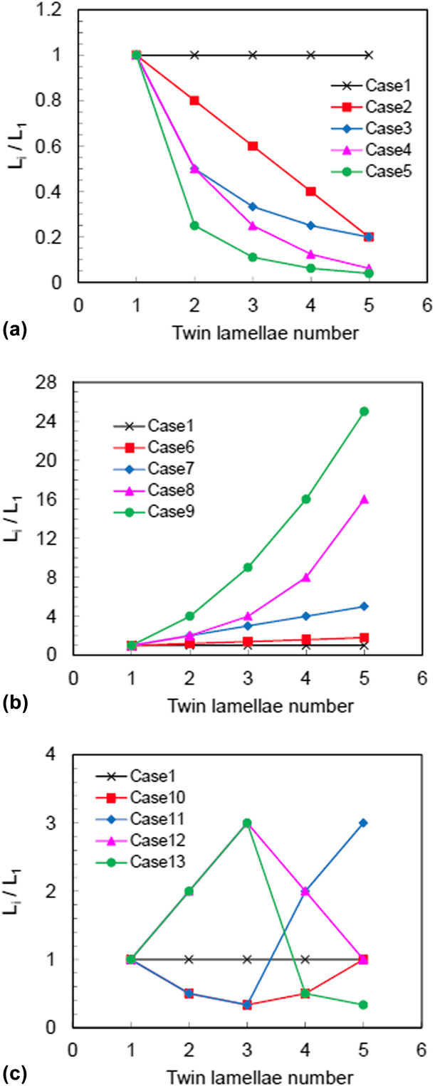
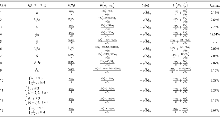
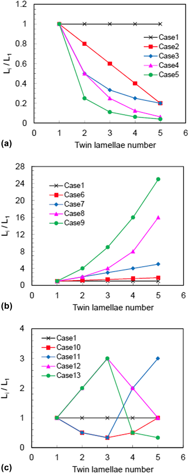
The above theoretical models can be applied to analyze the mechanical properties of materials with arbitrarily high-order HNTs [see Eqs. (21), (22), (27), (28), (45), and (53)]; regarding the practical application, the highest order is five based on the present manufacturing technology (see Ref. Reference Liu, Sun, Zhu, Liu, Lu and Lu29). In accord with the experimental capacity mentioned above, the highest order of HNTs is also set as N = 5 in the following discussions. Besides, for comparative analysis, 13 combinations for twin spacing of different layers of twin lamellae are constructed, and the corresponding expressions of ith scaled coefficient k i in different cases are listed in Table II. To illustrate the variation characteristics of twin spacing of different layers more clearly, Fig. 2 lists the ratios of the twin spacing of each layer to that of the primary layer, L i/L 1. It is seen that in Case 1 the twin spacing for each layer is set as the same, i.e., k i = k; in Cases 2–5, the twin spacing descends with the increase in layer order, and the decrement is magnified gradually; comparatively, in Cases 6–9, the twin spacing increases with the layer order, and the increment is also magnified gradually; in Cases 10–13, the increasing and decreasing tendencies of twin spacing with the layer order are mixed, and the corresponding variation amplitudes are also disordered.
Ratios of twin spacing of different layers of twin lamellae to that of the primary layer. (a) Cases 1–5, (b) Cases 6–9, and (c) Cases 10–13.
Twin spacing–dependent flow stress
Substituting the actual values of k i in Table II back into Eq. (45) leads to obtain expressions for the four material constants in Eq. (47), A(N 0),  $B\left( {n_{\rm{p}}^{\rm{'}},{\phi _0}} \right)$, C(ϕ0), and
 $D\left( {{N_0},n_{\rm{p}}^{\rm{'}}} \right)$, listed in Table II. It is seen that the parameter takes different values for different cases, and consequently, the dislocation density ρTB as well as its evolution characteristic with the variation of twin spacing are distinct from each other. Eventually, the amplitude of flow stress is distinct for different cases.
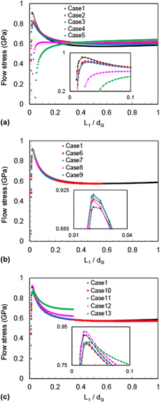
In the following, the effect of twin spacing on the flow stress will further be discussed based on the practical material parameters in Table I. Integrated with Tables I and II and Eqs. (1), (9), (11), and (47), σflow can be calculated, and its variation characteristics with the first scaled coefficient of the twin spacing of the primary layer of twin lamellae to the grain size, k = L 1/d G, are shown in Fig. 3, wherein the inset is magnification of the local zone. As the present emphasis is on the effect of twin spacing, a typical grain size of d G = 500 nm is adopted in related calculations; besides, note that ρI in Eq. (9) increases with the plastic strain εp, in the calculations a typical value of  $\varepsilon _{\rm{0}}^{\rm{p}} = 0.05$ is selected. Moreover, it is worth noting that the maximum value of scaled coefficient in various combinations of twin spacing should ensure all the twin spacing in the corresponding case is less than the grain size, i.e., max(k i = f(i)k) < 1.
Variation characteristics of flow stress with the twin spacing of primary layer of twin lamellae corresponding to different combinations of twin spacing. (a) Cases 1–5, (b) Cases 6–9, and (c) Cases 10–13.
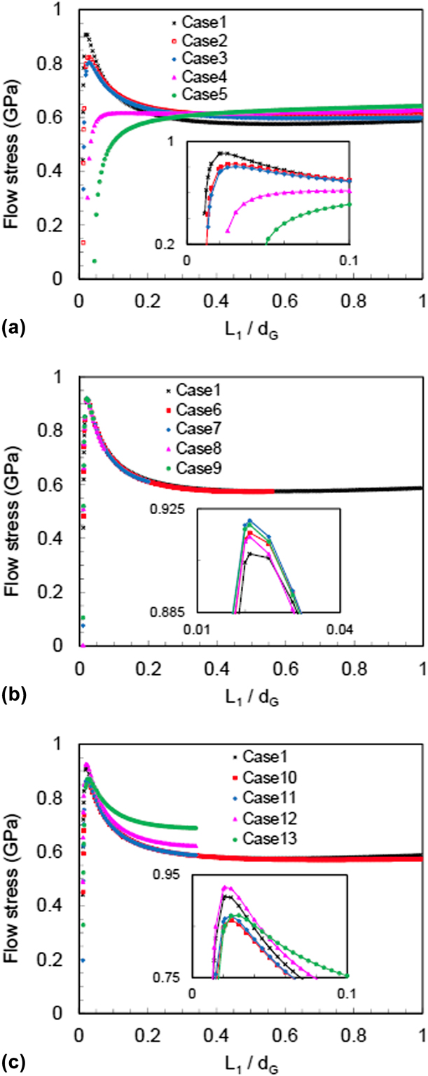
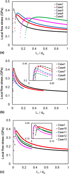
It is seen from Fig. 3 that there indeed exist two softening stages for the flow stress in all other cases except Case 5; however, the variation of σflow is relatively moderate after k > 0.2. In special, in various, cases there is a critical scaled coefficient k crit–Max at which σflow achieves the peak value, and for Cases 1–4, k crit–Max increases gradually along with the decrement in twin spacing of the high-order layers; comparatively, the values of k crit–Max are similar to each other for Cases 6–13. The exact values calculated from Eq. (52a) based on Tables I and II are listed in the last column of Table II, wherein Case 5 does not have an extreme point.
Due to the existence of the critical scaled coefficient k crit–Max, it can be inferred that the critical twin spacing of the primary layer corresponding to the peak flow stress may change along with the grain size. Actually, related MD simulations indeed demonstrated such a feature [Reference Li, Wei, Lu, Lu and Gao33, Reference Wei34]. Besides, the experimental investigations on the nanotwinned copper with grain size of d G = 400–600 nm show that the critical twin spacing corresponding to the peak strength is around 15 nm [Reference Lu, Shen, Chen, Qian and Lu12, Reference Shen, Lu, Lu, Jin and Lu13, Reference Shan, Lu, Minor, Stach and Mao14, Reference Lu, Chen, Huang and Lu15, Reference Lu, Dao, Zhu and Li16, Reference Lu, Zhu, Shen, Dao, Lu and Suresh17, Reference You, Lu and Lu18]. Table II shows that the critical scaled coefficients derived from the parameters of nanotwinned copper are all about 2.1%, except for Cases 2–5. Therefore, the critical twin spacing of the primary layer is about L 1–crit = 12.6 nm corresponding to a grain size of d G = 600 nm, which is consistent with the experiment result. Consequently, it has been shown that our theoretical models and material parameters are reasonable and applicable in practical application.
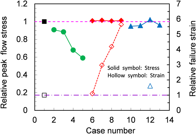
In particular, Fig. 3(a) shows that the peak flow stress descends gradually for Cases 1–5, whereas it increases gradually for Cases 6–9. For Cases 10–13, the decreasing and increasing tendencies show a mixed characteristic. For convenience of comparative analysis, Fig. 4 lists the relative peak flow stress derived from the peak flow stress in each case divided by that in Case 1, in which the peak stress in Case 5 is adopted as the value at k = 0.2, as there is no extreme point. It is seen that when the twin spacing of some high-order layer is smaller than that of the primary layer (Cases 2–5, 10, 11, and 13), the corresponding peak flow stress is lower than that in Case 1 with the equal twin spacing for different orders of HNTs, and the value is lower for the case with thinner twin spacing. Comparatively, when all the twin spacing of the high-order layer is larger than that of the primary layer (Cases 6–9, 12), the peak stress is always higher than that in Case 1; however, the increment is not significant, and the values in different cases are similar to each other.
Relative peak flow stress and relative failure strain corresponding to different combinations of twin spacing.
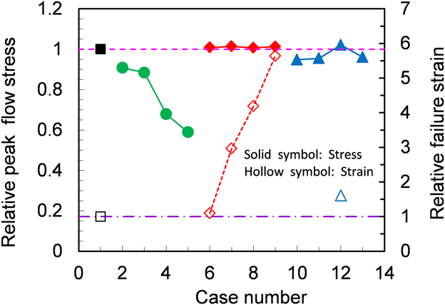
The main reason for these characteristics is that the activated dislocation slip system will be switched along with the variation of twin spacing. When the twin spacing is less than some critical value, the deformation mechanism will be shifted from full dislocation pile-up against and slip transfer across TBs to partial dislocation gliding on TBs [Reference Lu, Chen, Huang and Lu15, Reference Li, Wei, Lu, Lu and Gao33]. Besides, as the intersections between TBs and GBs are usually the regions with stress concentration, partial dislocations are easily nucleated in these intersections. When the twin spacing becomes thinner, the critical stress for the nucleation and gliding of partial dislocations will be weakened, and more intersections between TBs and GBs are generated. Consequently, the material strength will be dominated by the nucleation and gliding of partial dislocations at TBs, and it leads to the softening effect [Reference Li, Wei, Lu, Lu and Gao33]. Moreover, the detwinning activity and the partial dislocation–induced coherency loss of TBs may also induce the softening effect when the twin spacing is smaller than a critical value [Reference Yuan and Wu39, Reference Yuan, Chen, Jiang and Wu41]. Regarding the present theoretical models, along with the reduction in twin spacing L i, the third term in Eqs. (22) and (45), which is related to the partial dislocation, will be amplified significantly under a coefficient of 1/L i2. This will lead to the decrease in ρTB, and it eventually softens the strength of materials.
Besides, it needs to be pointed out that related derivations of the above theoretical formulae are based on an assumption that the twin spacing is large enough. When the twin spacing is less than two times of thickness of the TBDPZ, i.e., L i < 2d TBDPZ ∼ 7 nm, the expression of local mean strain gradient in Eq. (12) is no longer applicable, and the corresponding analysis on this condition can be seen in the work of Zhu et al. [Reference Zhu, Qu, Guo and Lu60]. For the conditions in Fig. 3, i.e., d G = 500 nm and k crit–Max ≈ 2.1%, when the twin spacing of the primary layer of twin lamellae takes the critical value of L 1 = 10.5 nm, the twin spacing of the secondary layer is already close to 7 nm for Cases 2–5, and that of the high-order layers will be all less than the limit value, especially, the smallest twin spacing in Case 5 will be only L 5 = 0.42 nm. Similarly, the values of L 2, L 3, and L 4 in Case 10, L 2 and L 3 in Case 11, and L 4 and L 5 in Case 13 are all close to or less than the limit value. Such small twin spacing will make the theoretical formulae inapplicable, and it is no longer physically meaningful in the practical material design.
Hence, regarding the aspect of strengthening materials, the twin spacing of the primary layer of twin lamellae should take the critical value, and the twin spacing of the high-order layers should be designed not below that of the primary layer, i.e., L i ≥ L 1.
Twin spacing–dependent ductility
Similar to the analysis in section “Twin spacing–dependent flow stress”, the values of the three material constants in Eq. (54),  ${A^'}\left( {n_{\rm{p}}^{\rm{'}}} \right)$, B′(ϕ0), and C′(N 0), can also be obtained by substituting the values of k i in Table II into Eq. (53), and the corresponding expressions are listed in Table III. Similarly, different values of parameters in various cases will lead to different magnitudes of
 ${}_{\rm{L}}{\rho _{{\rm{TB}}}}$ as well as its evolution characteristics with the variation of twin spacing and in turn induce different failure strain
 $\varepsilon _{{\rm{fail}}}^{\rm{p}}$.
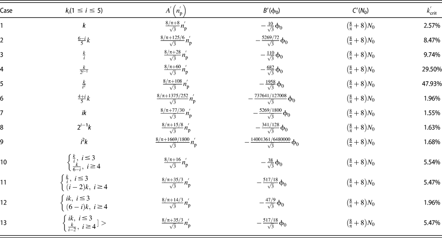
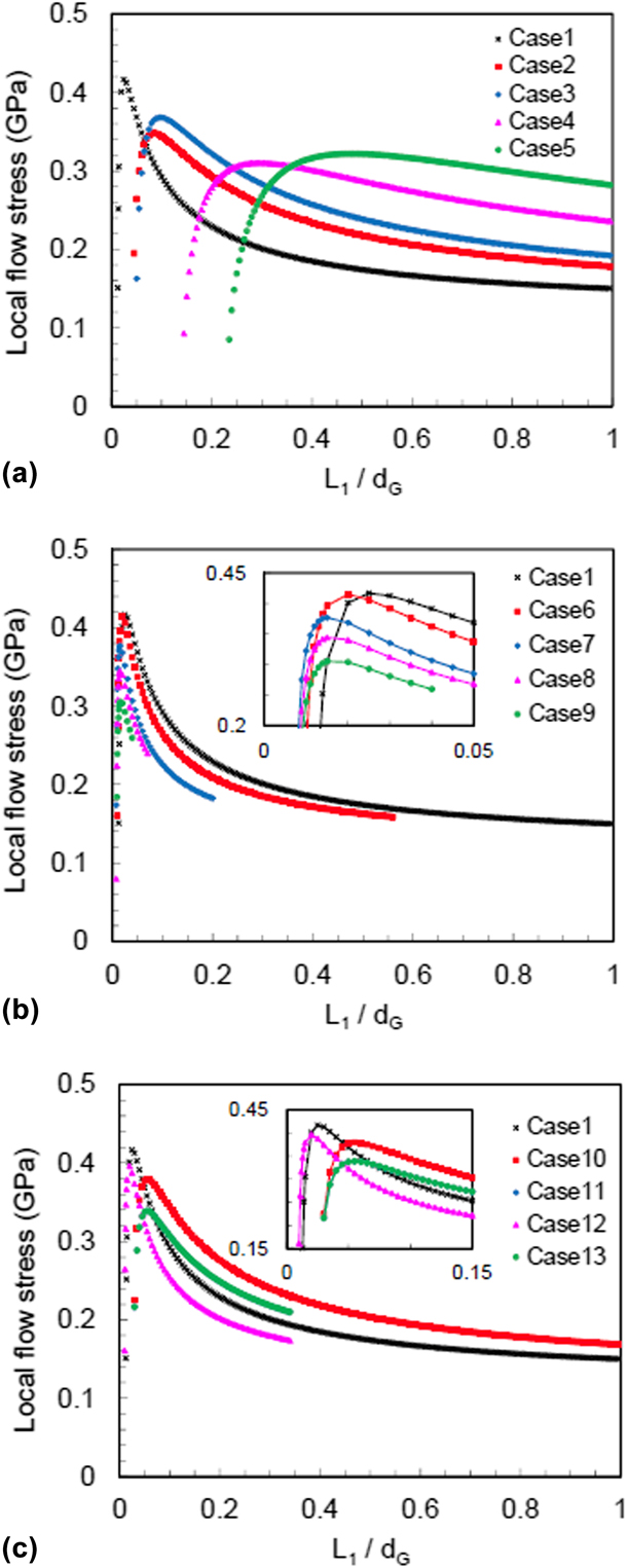
Similarly, integrated with Table III and Eqs. (9), (25), and (54), the values of  ${}_{\rm{L}}{\tau _{{\rm{flow}}}}$ and its variation characteristics with the first scaled coefficient k = L 1/d G are obtained and shown in Fig. 5. At the same time, based on Table III and Eqs. (43) and (54), related variation characteristics of
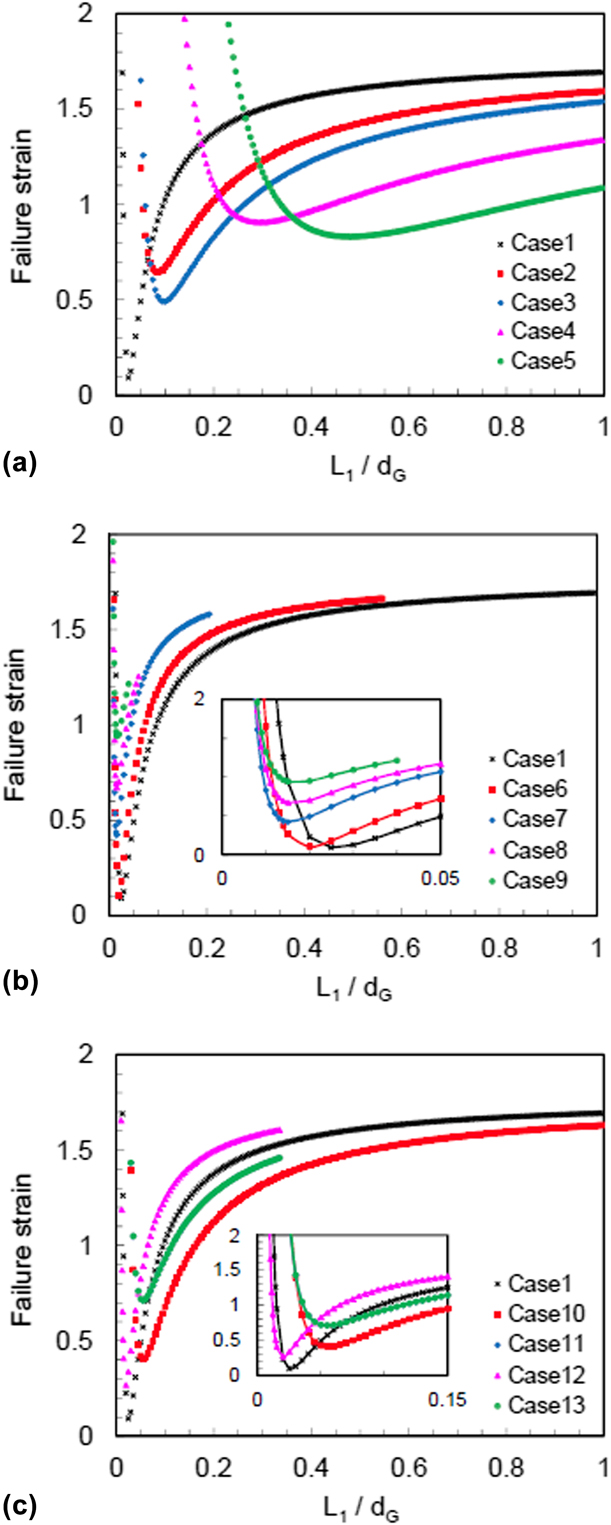
 $\varepsilon _{{\rm{fail}}}^{\rm{p}}$ with k = L 1/d G can also be obtained, as shown in Fig. 6. The inset in these two figures is also the magnification of local zone. The above analysis in Figs. 3 and 4 demonstrated that for cases with condition of L i < L 1 (Cases 2–5, 10, 11, 13), the small twin spacing will lead to the softening effect for the strength, and this phenomenon should be evaded in the practical material design. Consequently, though the curves in all cases are listed in Figs. 5 and 6, the following analysis will focus on the cases with L i ≥ L 1 only, i.e., Cases 1, 6–9, and 12.
Variation characteristics of local flow stress with the twin spacing of primary layer of twin lamellae corresponding to different combinations of twin spacing. (a) Cases 1–5, (b) Cases 6–9, and (c) Cases 10–13.
Variation characteristics of failure strain with the twin spacing of primary layer of twin lamellae corresponding to different combinations of twin spacing. (a) Cases 1–5, (b) Cases 6–9, and (c) Cases 10–13.
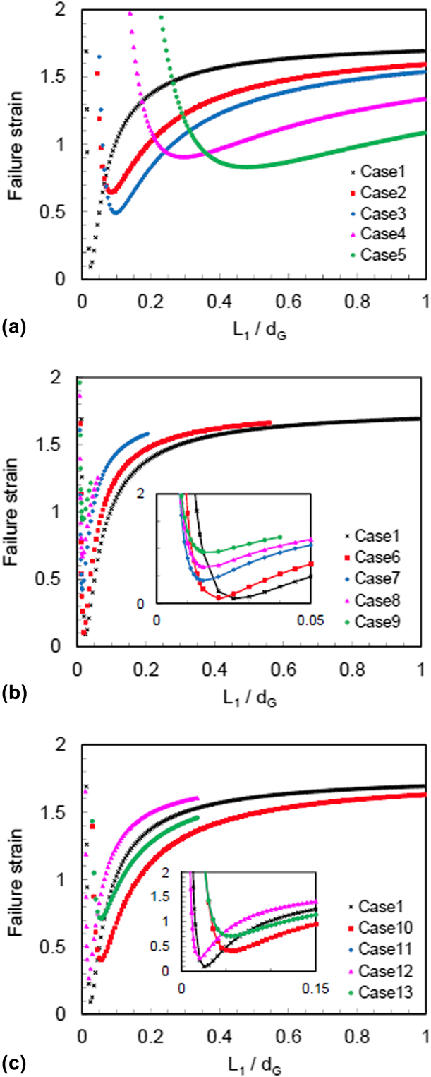
Figure 5 shows that there also exists a critical scaled coefficient  $k_{{\rm{crit}}}^{\rm{'}}$ at which
 ${}_{\rm{L}}{\tau _{{\rm{flow}}}}$ takes the maximum value and correspondingly
 $\varepsilon _{{\rm{fail}}}^{\rm{p}}$ takes the minimum value at this critical coefficient, as shown in Fig. 6. This implies that the critical twin spacing of the primary layer of twin lamellae corresponding to the lowest ductility will also change with the grain size. The exact values of
 $k_{{\rm{crit}}}^{\rm{'}}$ obtained from Eq. (57) based on parameters in Tables I and III are listed in the last column of Table III. It is seen that for the cases (Cases 6–9, 12) in which the twin spacing of all layers of twin lamellae is not smaller than that of the primary layer, the values of
 $k_{{\rm{crit}}}^{\rm{'}}$ are less than that in the case with equal twin spacing (Case 1), while the values of
 $k_{{\rm{crit}}}^{\rm{'}}$ for cases 2–5, 10–11, and 13 are greater than that in Case 1. Besides, the values of
 $k_{{\rm{crit}}}^{\rm{'}}$ and k crit–Max are different from each other in all cases (see Tables II and III), and this indicates that the highest strength of hierarchically nanotwinned metals does not necessarily correspond to the lowest ductility, which is different from other kinds of metals with the inverse relationship between strength and ductility. This characteristic is of great importance for the microstructure optimization.
Especially, Fig. 5(b) shows that the peak values of  ${}_{\rm{L}}{\tau _{{\rm{flow}}}}$ in Cases 6–9 descend gradually, and the peak value in Case 12 is also lower than that in Case 1, as shown in Fig. 5(c). Correspondingly, the bottom values of
 $\varepsilon _{{\rm{fail}}}^{\rm{p}}$ in these cases are all greater than that in Case 1, as shown in Figs. 6(b) and 6(c), and the failure strain is higher in the case with thicker twin spacing. This implies that increasing the twin spacing of the high-order layers of twin lamellae gradually is beneficial to improve the ductility. The main cause is that the plastic deformation in the thick twin lamellae is governed by the slip and interactions of full dislocations. The slip of dislocations is easier corresponding to the larger twin spacing; thus, the material could carry more plastic deformation. Besides, when the twin lamellae become thicker, the number of twin lamellae will decrease and fewer intersections between TBs and GBs are generated; consequently, the regions with stress concentration and the nucleating points for the microcrack decrease. Eventually the monolithic ductility of materials is enhanced.
As mentioned above, the expectation for the comprehensive mechanical properties is the simultaneous high strength and high ductility. It is seen in Fig. 4 that the peak flow stress increases a little when the twin spacing of the high-order layers of twin lamellae is greater than that of the primary layer; however, it is similar to each other corresponding to different cases. Comparatively, Figs. 5 and 6 show that at the critical scaled coefficient k crit–Max corresponding to the peak flow stress, the values of local flow stress  ${}_{\rm{L}}{\tau _{{\rm{flow}}}}$ and failure strain
 $\varepsilon _{{\rm{fail}}}^{\rm{p}}$ are distinct from each other among different cases. For comparative analysis, substitute the values of k crit–Max in Cases 1, 6–9, and 12 into Eqs. (43) and (54) for the calculation of the corresponding values of
 $\varepsilon _{{\rm{fail}}}^{\rm{p}}$, then the relative failure strain can be obtained through dividing the failure strain in each case by value in Case 1, which is also shown in Fig. 4. It is seen that though the peak flow stress in various cases is similar, the failure strain in Cases 6–9 and 12 is higher than that in Case 1, and the improvement is more significant for the larger increment in twin spacing of the high-order layers, e.g., the value of
 $\varepsilon _{{\rm{fail}}}^{\rm{p}}$ in Case 9 is more than five times of that in Case 1. Hence, increasing gradually the twin spacing of the high-order layers of twin lamellae is beneficial to improve the ductility.
Effect of grain size
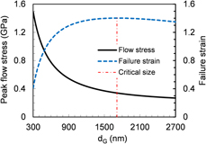
It is known from section “Grain size” that with decreasing the grain size, the flow stress will increase monotonously; comparatively, the variation of ductility is divided into two stages, i.e., the failure strain will descend with the reduction in grain size within the range of d G < d G–crit, and it displays an increasing tendency with decreasing the grain size when d G > d G–crit. Here, Case 9 (the combination of twin spacing with the highest strength and ductility) is selected as an example to discuss the effect of grain size. Based on parameters in Tables I–III, the variation curves of the peak flow stress and the failure strain with the grain size are obtained and shown in Fig. 7. It is seen that within the range of d G < 1000 nm, the flow stress and the failure strain, respectively, increases and decreases rapidly with decreasing the grain size; comparatively, both variations become relatively moderate after d G > 1000 nm. The critical gran size calculated from Eq. (64) is d G–crit = 1712.36 nm, which is obviously larger than the usual grain size in the nanocrystalline metals (<1000 nm).
Variation characteristics of peak flow stress and failure strain with the grain size corresponding to the combination of twin spacing in Case 9.
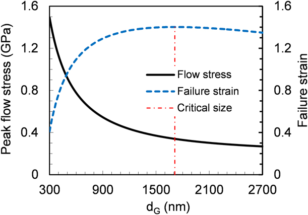
Hence, it can be inferred that for most of the hierarchically nanotwinned metals, e.g., steel and silver, the critical gran size would be greater than the actual grain size; thus, the reduction in grain size is still beneficial to their strength, whereas harmful to the ductility, and the trade-off dilemma between the two properties is still hard to overcome by adjusting the grain size. Nevertheless, the critical grain size could be a theoretical guidance for the microstructure design, and it would be practical for some kinds of materials whose critical grain size is small enough.
Conclusions
In the present paper, the theoretical models for the strength and ductility of high-order hierarchically nanotwinned metals are developed, and the analytical expressions of mechanical parameters with various factors are deduced. Related mechanism-based plasticity models can represent well the influences of various factors on the mechanical properties of materials, and the corresponding size effect can be analyzed systemically based on these theoretical models. The effects of twin spacing and grain size on the strength and ductility are discussed in detail, and a microstructure optimization approach toward the simultaneous high strength and high ductility is suggested.
The twin spacing has significant effect on the mechanical properties. Corresponding to various combinations of twin spacing of different layers of twin lamellae, there exists a critical twin spacing for the primary layer, which makes the strength reach the highest value, and the critical value displays a direct proportional relationship to the grain size. When the twin spacing of some high-order layer is smaller than that of the primary layer, it would result in a softening effect to the peak strength of materials (corresponds to the critical twin spacing of the primary layer). When all the high-order layers are thicker than the primary layer, the peak strength could reach a high level, and it is similar corresponding to different combinations of twin spacing. Besides, the ductility can be improved by increasing gradually the twin spacing of the high-order layers of twin lamellae, and the improvement is more significant corresponding to the larger magnification of twin spacing. Hence, simultaneous high strength and high ductility could be achieved by adjusting the combination of twin spacing for various layers.
The grain size also plays an important role, and the reduction in grain size leads to a positive effect on the strength, whereas a negative influence on the ductility of the hierarchically nanotwinned metals. The inverse relationship between strength and ductility is still hard to overcome by adjusting the grain size.
In the practical material design, to achieve expected comprehensive mechanical properties with high strength and high ductility, the twin spacing of the primary layer of twin lamellae should adopt the critical value, that of the high-order layers should be amplified gradually, and the larger magnification may lead to higher ductility.
Acknowledgments
The project is supported by China Scholarship Council (201604890008), National Natural Science Foundation of China (11602258), and the key subject “Computational Solid Mechanics” of China Academy of Engineering Physics.