1. Introduction
One of the severe consequences of the plasma disruptions in tokamaks is the generation of the runaway electron (RE) beams (see e.g. Wesson et al. Reference Wesson, Gill, Hugon, Schüller, Snipes, Ward, Bartlett, Campbell, Duperrex, Edwards, Granetz, Gottardi, Hender, Lazzaro, Lomas, Lopes Cardozo, Mast, Nave, Salmon, Smeulders, Thomas, Tubbing, Turner and Weller1989; Gill Reference Gill1993; Schüller Reference Schüller1995; Gill et al. Reference Gill, Alper, Edwards, Ingesson, Johnson and Ward2000, Reference Gill, Alper, de Baar, Hender, Johnson and Riccardo2002; Wesson Reference Wesson2004; Boozer Reference Boozer2012; Papp et al. Reference Papp, Fülöp, Fehér, de Vries, Riccardo, Reux, Lehnen, Kiptily, Plyusin and Alper2013 and references therein). The REs generated during the disruptions of tokamak plasmas may reach several tens of MeV and may contribute to a significant part of post-disruption plasma current. The prevention of such RE beams is of paramount importance in future tokamaks, especially in the ITER operation, since it may severely damage a device wall (Bécoulet et al. Reference Bécoulet, Hoang, Abiteboul, Achard, Alarcon, Alba-Duran, Allegretti, Allfrey, Amiel, Ane, Aniel, Antar, Argouarch, Armitano, Arnaud, Arranger, Artaud, Audisio, Aumeunier, Autissier, Azcona, Back, Bahat, Bai, Baiocchi, Balaguer, Balme, Balorin, Barana, Barbier, Barbuti, Basiuk, Baulaigue, Bayetti, Baylard, Beaufils, Beaute, Bécoulet, Bej, Benkadda, Benoit, Berger-By, Bernard, Berne, Bertrand, Bertrand, Beyer, Bigand, Bonhomme, Borel, Boron, Bottereau, Bottollier-Curtet, Bouchand, Bouquey, Bourdelle, Bourg, Bourmaud, Brémond, Bribiesca Argomedo, Brieu, Brun, Bruno, Bucalossi, Bufferand, Buravand, Cai, Cantone, Cantone, Caprin, Cartier-Michaud, Castagliolo, Belo, Catherine-Dumont, Caulier, Chaix, Chantant, Chatelier, Chauvin, Chenevois, Chouli, Christin, Ciazynski, Ciraolo, Clairet, Clapier, Cloez, Coatanea-Gouachet, Colas, Colledani, Commin, Coquillat, Corbel, Corre, Cottet, Cottier, Courtois, Crest, Dachicourt, Dapena Febrer, Daumas, de Esch, De Gentile, Dechelle, Decker, Decool, Deghaye, Delaplanche, Delchambre-Demoncheaux, Delpech, Desgranges, Devynck, Dias Pereira Bernardo, Dif-Pradalier, Doceul, Dong, Douai, Dougnac, Dubuit, Duchateau, Ducobu, Dugue, Dumas, Dumont, Durocher, Durocher, Duthoit, Ekedahl, Elbeze, Escarguel, Escop, Faïsse, Falchetto, Farjon, Faury, Fedorzack, Féjoz, Fenzi, Ferlay, Fiet, Firdaouss, Francisquez, Franel, Frauche, Frauel, Futtersack, Garbet, Garcia, Gardarein, Gargiulo, Garibaldi, Garin, Garnier, Gauthier, Gaye, Geraud, Gerome, Gervaise, Geynet, Ghendrih, Giacalone, Gibert, Gil, Ginoux, Giovannangelo, Girard, Giruzzi, Goletto, Goncalves, Gonde, Goniche, Goswami, Grand, Grandgirard, Gravil, Grisolia, Gros, Grosman, Guigue, Guilhem, Guillemaut, Guillerminet, Guimaraes Filho, Guirlet, Gunn, Gurcan, Guzman, Hacquin, Hariri, Hasenbeck, Hatchressian, Hennequin, Hernandez, Hertout, Heuraux, Hillairet, Honore, Hornung, Houry, Hunstad, Hutter, Huynh, Icard, Imbeaux, Irishkin, Isoardi, Jacquinot, Jacquot, Jiolat, Joanny, Joffrin, Johner, Joubert, Jourd’Heuil, Jouve, Junique, Keller, Klepper, Kogut, Kubic̆, Labasse, Lacroix, Lallier, Lamaison, Lambert, Larroque, Latu, Lausenaz, Laviron, Le, Le Luyer, Le Niliot, Le Tonqueze, Lebourg, Lefevre, Leroux, Letellier, Li, Lipa, Lister, Litaudon, Liu, Loarer, Lombard, Lotte, Lozano, Lucas, Lütjens, Magaud, Maget, Magne, Mahieu, Maini, Malard, Manenc, Marandet, Marbach, Marechal, Marfisi, Marle, Martin, Martin, Martin, Martinez, Martino, Masset, Mazon, Mellet, Mercadier, Merle, Meshcheriakov, Messina, Meyer, Millon, Missirlian, Moerel, Molina, Mollard, Moncada, Monier-Garbet, Moreau, Moreau, Moreau, Morel, Moriyama, Motassim, Mougeolle, Moulton, Moureau, Mouyon, Naim Habib, Nardon, Négrier, Nemeth, Nguyen, Nguyen, Nicolas, Nicolas, Nicollet, Nilsson, N’Konga, Noel, Nooman, Norscini, Nouailletas, Oddon, Ohsako, Orain, Ottaviani, Pagano, Palermo, Panayotis, Parrat, Pascal, Passeron, Pastor, Patterlini, Pavy, Pecquet, Pégourié, Peinturier, Pelletier, Peluso, Petrzilka, Peysson, Pignoly, Pirola, Pocheau, Poitevin, Poli, Poli, Pompon, Porchy, Portafaix, Preynas, Prochet, Prou, Ratnani, Raulin, Ravenel, Renard, Ricaud, Richou, Ritz, Roche, Roubin, Roux, Ruiz, Sabathier, Sabot, Saille, Saint-Laurent, Sakamoto, Salasca, Salmon, Salmon, Samaille, Sanchez, Santagiustina, Saoutic, Sarazin, Sardain, Schlosser, Schneider, Schwob, Segui, Seguin, Selig, Serret, Signoret, Signoret, Simonin, Soldaini, Soler, Soltane, Song, Sourbier, Sparagna, Spitz, Spuig, Storelli, Strugarek, Tamain, Tena, Theis, Thomine, Thouvenin, Torre, Toulouse, Travére, Tsitrone, Turck, Urban, Vallet, Vallory, Valognes, Van Helvoirt, Vartanian, Verger, Vermare, Vermare, Vezinet, Vicente, Vidal, Vignal, Vigne, Villecroze, Villedieu, Vincent, Volpe, Volpe, Volpe, Wagrez, Wang, Wauters, Wintersdorff, Wittebol, Zago, Zani, Zarzoso, Zhang, Zhong and Zou2013).
At present there are several proposals to mitigate REs generated during plasma disruptions. The mitigation of REs by gas injections has been discussed (see e.g. Whyte et al. Reference Whyte, Jernigan, Humphreys, Hyatt, Lasnier, Parks, Evans, Rosenbluth, Taylor, Kellman, Gray, Hollmann and Combset2002, Reference Whyte, Jernigan, Humphreys, Hyatt, Lasnier, Parks, Evans, Taylor, Kellman, Gray and Hollmannet2003; Bakhtiari et al. Reference Bakhtiari, Kawano, Tamai, Miura, Yoshino and Nishida2002, Reference Bakhtiari, Tamai, Kawano, Kramer, Isayama, Nakano, Kamiya, Yoshino, Miura and Nishida2005; Granetz et al. Reference Granetz, Hollmann, Whyte, Izzo, Antar, Bader, Bakhtiari, Biewer, Boedo, Evans, Hutchinson and Jernigan2007; Hender et al. Reference Hender, Wesley, Bialek, Bondeson, Boozer, Buttery, Garofalo, Goodman, Granetz, Gribov, Gruber, Gryaznevich, Giruzzi, Günter, Hayashi, Helander, Hegna, Howell, Humphreys, Huysmans, Hyatt, Isayama, Jardin, Kawano, Kellman, Kessel, Koslowski, La Haye, Lazzaro, Liu, Lukash, Manickam, Medvedev, Mertens, Mirnov, Nakamura, Navratil, Okabayashi, Ozeki, Paccagnella, Pautasso, Porcelli, Pustovitov, Riccardo, Sato, Sauter, Schaffer, Shimada, Sonato, Strait, Sugihara, Takechi, Turnbull, Westerhof, Whyte, Yoshino and Zohm2007; Bozhenkov et al. Reference Bozhenkov, Lehnen, Finken, Jakubowski, Wolf, Jaspers, Kantor, Marchuk, Uzgel, VanWassenhove, Zimmermann and Reiter2008; Lehnen et al. Reference Lehnen, Abdullaev, Arnoux, Bozhenkov, Jakubowski, Jaspers, Plyusnin, Riccardo and Samm2009; Pautasso et al. Reference Pautasso, Coster, Eich, Fuchs, Gruber, Gude, Herrmann, Igochine, Konz, Kurzan, Lackner, Lunt, Marascheck, Mlynek, Reiter, Rohde, Zhang, Bonnin, Beck and Prausner2009; Hollmann et al. Reference Hollmann, Commaux, Eidietis, Evans, Humphreys, James, Jernigan, Parks, Strait, Wesley, Yu, Austin, Baylor, Brooks, Izzo, Jackson, van Zeeland and Wu2010; Reux et al. Reference Reux, Bucalossi, Saint-Laurent, Gil, Moreau and Maget2010 and Lehnen et al. Reference Lehnen, Alonso, Arnoux, Baumgarten, Bozhenkov, Brezinsek, Brix, Eich, Gerasimov, Huber, Jachmich, Kruezi, Morgan, Plyusnin, Reux, Riccardo, Sergienko and Stamp2011). Suppression of REs by resonant magnetic perturbations (RMPs) has been also intensively discussed since the late 1990s (see e.g. Kawano et al. Reference Kawano, Yoshino, Kondoh, Isei, Ishida, Tobita, Hatae, Itami and Sakasai1997; Tokuda and Yoshino Reference Tokuda and Yoshino1999; Helander et al. Reference Helander, Eriksson and Andersson2000; Yoshino and Tokuda Reference Yoshino and Tokuda2000; Lehnen et al. Reference Lehnen, Bozhenkov, Abdullaev and Jakubowski2008, Reference Lehnen, Abdullaev, Arnoux, Bozhenkov, Jakubowski, Jaspers, Plyusnin, Riccardo and Samm2009; Hollmann et al. Reference Hollmann, Commaux, Eidietis, Evans, Humphreys, James, Jernigan, Parks, Strait, Wesley, Yu, Austin, Baylor, Brooks, Izzo, Jackson, van Zeeland and Wu2010 and Papp et al. Reference Papp, Drevlak, Fülöp, Helander and Pokol2011, Reference Papp, Drevlak, Fülöp and Pokol2012). However, up to now there is no regular strategy to solve this problem. One of the reasons is that the physical mechanisms of the formation of REs during plasma disruptions are still not well known. The different scenarios of runaway formation during plasma disruptions have been discussed in the literature. Particularly, in Fülöp et al. (Reference Fülöp, Smith and Pokol2009), Fülöp and Newton (Reference Fülöp and Newton2014), the possible roles of whistler waves in the generation of REs and Alfvénic wave instabilities driven by REs have been discussed.
There were numerous dedicated experiments to study the problem of runaway current generation during plasma disruptions triggered by massive gas injections (MGIs) in the TEXTOR tokamak (see e.g. Forster et al.
Reference Forster, Finken, Kudyakov, Lehnen, Willi, Xu and Zeng2012; Zeng et al.
Reference Zeng, Koslowski, Liang, Lvovskiy, Lehnen, Nicolai, Pearson, Rack, Jaegers, Finken, Wongrach and Xu2013; Wongrach et al.
Reference Wongrach, Finken, Abdullaev, Koslowski, Willi and Zeng2014), in the KSTAR tokamak (Chen et al.
Reference Chen, Kim, Yu, England, Yoo, Hahn, Yoon, Lee, Oh, Kwak and Kwon2013), in the JET tokamak (Plyusnin et al.
Reference Plyusnin, Riccardo, Jaspers, Alper, Kiptily, Mlynar, Popovichev, de La Luna and Andersson2006; Lehnen et al.
Reference Lehnen, Alonso, Arnoux, Baumgarten, Bozhenkov, Brezinsek, Brix, Eich, Gerasimov, Huber, Jachmich, Kruezi, Morgan, Plyusnin, Reux, Riccardo, Sergienko and Stamp2011), in DIII-D (Hollmann et al.
Reference Hollmann, Commaux, Eidietis, Evans, Humphreys, James, Jernigan, Parks, Strait, Wesley, Yu, Austin, Baylor, Brooks, Izzo, Jackson, van Zeeland and Wu2010; Commaux et al.
Reference Commaux, Baylor, Combs, Eidietis, Evans, Foust, Hollmann, Humphreys, Izzo, James, Jernigan, Meitner, Parks, Wesley and Yu2011; Hollmann et al.
Reference Hollmann, Austin, Boedo, Brooks, Commaux, Eidietis, Humphreys, Izzo, James, Jernigan, Loarte, Martin-Solis, Moyer, Muñoz-Burgos, Parks, Rudakov, Strait, Tsui, Van Zeeland, Wesley and Yu2013), in Alcator C-Mod (Olynyk et al.
Reference Olynyk, Granetz, Reinke, Whyte, Golfinopoulos, Hughes, Walk, Izzo, Combs, Milora and Brookman2013), and others. In these works the dependences of RE generation on the toroidal magnetic field, on the magnetic field fluctuations, and on the species of injection gases have been investigated. Particularly, in the KSTAR tokamak (Chen et al.
Reference Chen, Kim, Yu, England, Yoo, Hahn, Yoon, Lee, Oh, Kwak and Kwon2013), it has been found that there is no toroidal magnetic field threshold
 $B_{T}<2~\text{T}$
, as was indicated by previous experiments in other tokamaks. In Izzo et al. (Reference Izzo, Hollmann, James, Yu, Humphreys, Lao, Parks, Sieck, Wesley, Granetz, Olynyk and Whyte2011, Reference Izzo, Humphreys and Kornbluth2012), magneto-hydro-dynamics (MHD) simulations have been performed to study the confinement of REs generated during rapid disruptions by MGIs in DIII-D, Alcator C-Mod, and ITER. Such simulations with two different MHD codes have been carried out by Izzo et al. (Reference Izzo, Humphreys and Kornbluth2012) to analyse shot-to-shot variability of RE currents in DIII-D tokamak discharges.
These numerous experiments show the complex nature of plasma disruption processes, especially the formation of RE beams, and their evolution. One of the important features of this event is its irregularity and variability of RE beam parameters from one discharge to another. This indicates the sensitivity of disruption processes and RE beam formations to initial conditions, which is the characteristic feature of nonlinear processes, particularly, a deterministic chaotic system. Therefore, ab initio numerical simulations of these processes may not always be successful to understand their mechanisms because of the complexity of computer simulations of nonlinear processes (Kadanoff Reference Kadanoff2004). The problem of numerical simulations of plasma disruptions is comprehensively discussed by Boozer (Reference Boozer2012). The present status of the theory of RE generation in ITER is reviewed in the recent paper by Boozer (Reference Boozer2015).
In this work we intend to approach this problem from the point of view of Hamiltonian chaotic systems, mainly the magnetic stochasticity in magnetically confined plasmas (Abdullaev Reference Abdullaev2014). Based on the ideas of these systems and analyses of numerous experimental results, mainly obtained in the TEXTOR tokamak, we propose possible mechanisms of formation and evolution of RE beams created during plasma disruptions. Since a self-consistent theoretical treatment of all these processes is very complicated, we developed theoretical models for each stage of a plasma disruption. These models are used to estimate the characteristic times of the thermal and current quenches (CQs), the spatial size of runaway plasma beams and their decay times, the speed of RE radial drifts, and the effect of magnetic perturbations.
It is believed that the plasma disruption starts due to a large-scale magnetic stochasticity caused by excited MHD modes with low poloidal
 $m$
and toroidal
 $n$
numbers (
 $m/n=1/1,2/1,3/2,5/2,\dots$
) (see e.g. Kadomtsev Reference Kadomtsev1984; Gill Reference Gill1993; Schüller Reference Schüller1995; Wesson Reference Wesson2004 and references therein). The heat and particle transports in the strongly chaotic magnetic field cause a fast temperature drop and stop the plasma current. However, at a certain spectrum of magnetic perturbations, for example at a sufficiently small amplitude of the
 $m/n=1/1$
mode, the chaotic field lines may not extend to the central plasma region due to the creation of an intact magnetic surface. In the case of plasmas with the safety factor
 $q(0)<1$
at magnetic axis
 ${\it\rho}=0$
the intact magnetic surface can be located between the magnetic surface
 $q=1$
and the nearest low-order rational surface
 $q=5/4$
(or
 $q=4/3,\dots$
). This intact magnetic surface confines particles in the central plasma region and serves as a transport barrier to particles during the CQ. Electrons in the confined region are accelerated due to the large toroidal electric field and form the relatively stable RE beams.
This occurs, for instance, when the plasma disruption is initiated by the heavy argon gas injection which does not penetrate deep into the plasma; therefore, it does not excite the
 $m/n=1/1$
mode with a sufficiently large amplitude. On the contrary, the injection of the lighter noble gases neon and helium does not generate runaways. The reason is that light gases penetrate deeper into the plasma and excite the large-amplitude
 $m/n=1/1$
mode.
The existence of an intact magnetic surface and its location depend on the radial profile of the safety factor and the spectrum of magnetic perturbations. The latter sensitively depends on the plasma disruption conditions and varies unpredictably from one discharge to another during plasma disruptions. This makes the RE formation process unpredictable and may explain a shot-to-shot variability of the parameters of RE beams.
The role of the safety factor profile in the formation of RE beams can be pronounced during disruptions of plasmas with reversed magnetic shear. In the plasmas with non-monotonic radial profiles of the safety factor there has been observed an improved confinement of energy and particles due to the internal transport barrier located near the minimal value of the safety factor, i.e. near the shearless magnetic surface (Levinton et al. Reference Levinton, Zarnstorff, Batha, Bell, Bell, Budny, Bush, Chang, Fredrickson, Janos, Manickam, Ramsey, Sabbagh, Schmidt, Synakowski and Taylor1995; Strait et al. Reference Strait, Lao, Mauel, Rice, Taylor, Burrell, Chu, Lazarus, Osborne, Thompson and Turnbull1995). During disruptions this magnetic surface acts as a robust magnetic barrier that separates a chaotic magnetic field formed in the outer region from penetration into the central plasma region. Electrons confined by the shearless magnetic surface can form a stable RE beam with a relatively large transversal size. Recently published results of the disruption experiments in the TFTR tokamak with the reversed magnetic shear indeed show the formation of a large RE beam with long confinement times (Fredrickson et al. Reference Fredrickson, Bell, Taylor and Medley2015).
Based on this mechanism, we study the three main stages of the post-disruption plasma evolution: the fast thermal quench (TQ), the CQ, and the RE beam evolution. The physical processes during each of these stages will be studied by theoretical models. These processes are the formation of a stochastic magnetic field, heat and particle transport in a stochastic magnetic field, the acceleration of electrons by an inductive electric field, the loss mechanisms of REs, and the effect of internal and external magnetic perturbations. A short report on this study is to be published in Abdullaev et al. (Reference Abdullaev, Finken, Wongrach, Tokar, Koslowski, Willi and Zheng2015).
The paper consists of eight sections. Mathematical tools and models employed to study the problems are given in the Supplementary Part available at http://dx.doi.org/10.1017/S0022377815000501. The numerous data obtained during the dedicated experiments in the TEXTOR tokamak are analysed in § 2. Possible mechanisms of plasma disruptions with RE beam formation are proposed and analysed in § 3. The transport of heat and particles during the fast TQ and the CQ stages of plasma disruption are studied in § 4. The model of a post-disruption plasma beam is proposed in § 5. Using this model, the time evolution of guiding-centre (GC) orbits of electrons accelerated by the inductive toroidal electric field is studied in § 6. Particularly, the change of RE confinement conditions with decreasing plasma current and increasing electron energy and the outward drift of GC orbits are investigated. The effect of external and internal magnetic perturbations on the RE confinement are discussed in § 7. In the final § 8, we give a summary of the obtained results and discuss their consequences.
2. Description of plasma disruptions
The TEXTOR was a middle size limiter tokamak with the major radius
 $R_{0}=1.75~\text{m}$
and the minor radius
 $a=0.46~\text{cm}$
. The toroidal field
 $B_{0}$
can be varied up to 2.8 T, and the plasma current taken up to 600 kA. In the experiments the plasma disruptions were triggered in a controlled way by gas injections using a fast disruption mitigation valve (DMV) (Bozhenkov et al.
Reference Bozhenkov, Finken, Lehnen and Wolf2007; Finken et al.
Reference Finken, Lehnen and Bozhenkov2008, Reference Finken, Lehnen and Bozhenkov2011; Bozhenkov et al.
Reference Bozhenkov, Lehnen, Finken, Bertschinger, Koslowski, Reiter and Wolf2011). Particularly, the disruptions with REs were triggered by argon (Ar) injection. The runaway-free disruptions were triggered by either helium or neon (He/Ne) injection performed by the smaller valve. The effect of the externally applied RMPs on the RE generations has been investigated using the dynamic ergodic divertor (DED) installed in the TEXTOR tokamak.
Below we analyse the experimental results of discharges with the pre-disruption plasma current
 $I_{p}=350~\text{kA}$
and the toroidal field
 $B_{t}=2.4~\text{T}$
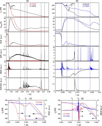
. Figure 1(a) illustrates typical disruptions of the discharges of the TEXTOR tokamak with and without RE generations. Specifically, it shows the time evolution of plasma parameters (the loop voltage
 $V_{loop}$
, the electron cyclotron emission (ECE), the soft X-ray (SXR) signal, the Mirnov signal, and the scintillation probe (ScProbe) signal during disruptions of the discharges with REs (nos 117 434, 117 859, 119 978 and 120 140) and without REs (no. 117 444)).
(a) Time evolution of the disruption of the TEXTOR shots no. 119 978 (black solid lines) and no. 117 444 (red curves) (from top to bottom): the plasma current, the loop voltage, the ECE signal, the SXR signal, the Mirnov signal, and the ScProbe signal. (b) The same but for the discharges no. 117 859 (blue curves) and no. 120 140 (black curves). (c) Initial stage of the temporal evolution of the plasma current (solid curve on the left-hand side axis) and ECE signal (right-hand side axis); (d) the Mirnov signal (right-hand side axis) during a plasma disruption with (nos 117 434 and 117 507) and without (no. 117 444) RE generations.
 $I_{p}^{(RE)}$
is the initial value of the plasma current with REs. Disruptions for discharges nos 117 434, 119 978, 117 507, 117 859 and 120 140 are initiated by Ar injections, and no. 117 444 by Ne injections.

There are also some discharges with untypical RE currents and shorter current decay times. The two examples of such discharges are shown in figure 1(b). We will discuss some features of these discharges at the end of the section.
The typical behaviour of the plasma during the disruptions is as follows. The gas (Ar or Ne/He) was injected at the time instant
 $t=2~\text{s}$
. One can distinguish three stages of the disruption with the REs: the first (or fast) stage in which a sudden temperature drop occurs, in the second stage the plasma current starts to decay with a higher rate, and in the third stage the current decay slows down and the current beam with the REs is formed.
2.1. Thermal quench stage
The first fast stage starts a few milliseconds (between 2 and 5 ms) after the gas injection and ends with a sudden temperature drop (a TQ) in a time interval of about 1 ms, as seen from the ECE signals shown in detail in figure 1(c). The Mirnov signals indicating magnetic activities start just before this time interval and they last a few milliseconds until a significant decay of the plasma current for the RE-free discharges or establishment of the current with the REs (see figure 1
a). The close-up views of the ECE signals and the Mirnov signals in this stage for the discharges with REs (no. 117 434) and without REs (no. 117 444) are shown in figure 1(c,d), respectively. The end times
 $t_{1}$
and
 $t_{2}$
of the TQ stages for these discharges are shown by vertical lines.
For our study, it is of importance to analyse in detail the difference in the time development of the TQ stage of disruptions without REs and with REs, initiated by the massive injection of lighter (Ne) and heavier (Ar) noble gases. (i) In figure 1(c), one can see that the TQ starts roughly at
 $2.6~{\rm\mu}\text{s}$
, in the former case, and at
 $3.7~{\rm\mu}\text{s}$
, in the latter one, after the initiation of injection. The ratio of these delay times is
 $0.7\approx 1/\sqrt{2}$
and can be well explained by the difference in the atomic weights
 $A_{g}$
of the gases in question. Indeed, the flow velocity
 $V_{g}\sim 1/\sqrt{A_{g}}$
of neon atoms is a factor of
 $\sqrt{2}$
higher than that for argon and, thus, neon atoms enter the plasma after a respectively shorter time.
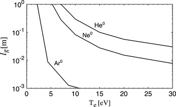
Dependence of the penetration length
 $l_{g}$
on the electron temperature
 $T_{e}$
for He, Ne, and Ar atoms. The electron density is
 $n_{e}=10^{19}~\text{m}^{-3}$
.

(ii) By comparing figure 1(c,d), we find that by injection of neon the TQ stage is finished (at time
 $t_{1}$
) before MHD perturbations are triggered. That is, in this case, TQ is completely due to cooling induced by the presence of impurity atoms squeezed in a narrow jet and penetrating deep enough into the plasma core. The penetration depth of gas atoms is
 $l_{g}=V_{g}/(k_{ion}^{0}n_{e})$
, where
 $k_{ion}^{0}$
is the ionization rate coefficient. Figure 2 displays
 $l_{g}$
versus the electron temperature
 $T_{e}$
with the electron density
 $n_{e}=10^{19}~\text{m}^{-3}$
computed for He, Ne, and Ar, by using the open atomic database ADAS (OPEN-ADAS: Atomic Data and Analysis Structure, http://open.adas.ac.uk/) for
 $k_{ion}^{0}$
and assuming that the gas jet has a radial velocity of two sound speeds at the room temperature. One can see that for light gases, He and Ne,
 $l_{g}$
can exceed the minor radius of TEXTOR of 0.46 m if inside the gas jet the plasma is cooled down to a temperature of several eV by energy losses on excitation and ionization of gas atoms and thermalization of generated electrons, as is demonstrated in Koltunov and Tokar (Reference Koltunov and Tokar2011). The rest of the magnetic surfaces is cooled down by the heat conduction along magnetic field lines to the jet area (Tokar and Koltunov Reference Tokar and Koltunov2013). Thus, the plasma is cooled down as a whole during a time of
 $a/V_{g}\approx 0.5{-}1~\text{ms}$
. Only later are tearing modes excited on numerous resonant magnetic surfaces due to the growth, as
 $1/T_{e}^{3/2}$
, of the plasma resistivity.
(iii) In the case of Ar, the penetration depth
 $l_{g}$
is much smaller, mostly due to the much larger ionization rate, than for He and Ne atoms and Ar gas is ionized at the plasma edge. Due to edge cooling very sharp radial gradients of the plasma resistivity and plasma current density
 $j$
are generated. Since the growth rate of tearing modes is
 ${\sim}(\text{d}j/\text{d}{\it\rho})^{4/5}$
(Wesson Reference Wesson2004), MHD modes resonant mostly on outer magnetic surfaces with the safety factor noticeably larger than 1 are triggered. The magnetic field stochastization due to these modes leads to the fast cooling of the main plasma volume during a time of 0.1–0.2 ms (see § 4.1). This explains why in shot no. 117 434 with Ar injection the temperature drop happens although later but faster than in shot no. 117 444 with Ne, and MHD activity starts to develop even before the TQ; see figure 1(c,d).
2.2. Current quench stage
The second stage of the plasma disruption begins with the current decay within a millisecond after the TQ. Particularly, for the discharges nos 117 434 and 117 444, the current decay starts in
 $0.47\times 10^{-3}~\text{s}$
and
 $0.87\times 10^{-3}~\text{s}$
, respectively, after the temperature drop (see figure 1
a,c). In discharges without the RE formation the current decays with the same rate until it completely disappears in a few milliseconds. In the discharges with the RE formation the strong current decay stops at a certain value of
 $I_{p}=I_{p}^{(RE)}$
and is replaced by a slower decay. The initial RE current
 $I_{p}^{(RE)}$
is shown in figure 1(a,b). In this stage the loop voltage starts to rise due to an inductive electric field opposing the current decay.
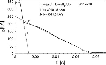
Determination of the average current decay rate
 $\langle \text{d}I_{p}/\text{d}t\rangle$
at the second and the third stages of the plasma disruptions. Solid curve describes the measured time evolution of the current
 $I_{p}(t)$
, dashed straight line
 $f(t)=a-bt$
approximates the average current decay. The coefficient
 $b$
gives the estimation of
 $|\langle \text{d}I_{p}/\text{d}t\rangle |$
. Curve 1 corresponds to the current decay stage and curve 2 corresponds to the RE current decay stage.

The time dependence of the plasma current
 $I_{p}$
in this stage for all discharges is well approximated by the linear function of time
 $I_{p}=I_{p0}-bt$
, where the coefficient
 $b=-\langle \text{d}I_{p}/\text{d}t\rangle$
determines the average current decay rate. The scheme of determination of
 $b=|\langle \text{d}I_{p}/\text{d}t\rangle |$
is shown in figure 3. The values of the current decay rate
 $\langle \text{d}I_{p}/\text{d}t\rangle$
during the CQ and RE plateau regimes and the initial RE current
 $I_{p}^{(RE)}$
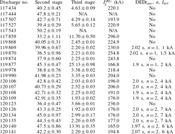
for a number of discharges are listed in table 1. It also shows the time
 $t_{max}$
when the applied RMP, i.e. the DED current
 $I_{ded}$
, reaches its maximal value, and the toroidal mode
 $n$
of the RMPs.
Parameters of discharges: first column – the discharge number; second and third columns – the average decay rates
 $|\langle \text{d}Ip/\text{d}t\rangle |$
(in
 $\text{MA}~\text{s}^{-1}$
) of the plasma current
 $I_{p}(t)$
in the second and the third stages; fourth column – the initial current of the RE beam
 $I_{p}^{(RE)}$
; the fifth column shows the parameters of the RMPs, a time
 $t_{max}$
when the DED current reaches its maximum value
 $I_{ded}$
, and the toroidal mode
 $n$
. Note that the discharges nos 117 444 and 117 543 are RE-free.

The dependences of
 $|\langle \text{d}I_{p}/\text{d}t\rangle |$
on the initial RE current
 $I_{p}^{(RE)}$
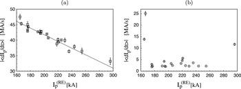
for a number of discharges are plotted in figure 4(a,b) in the CQ regime and the RE current decay stage, respectively. The current decay rate
 $|\langle \text{d}I_{p}/\text{d}t\rangle |$
for all discharges is of the same order and lies between 32 and
 $50~(\text{MA}~\text{s}^{-1})$
, as listed in the second column of table 1 and shown in figure 4(a). The highest value of
 $|\langle \text{d}I_{p}/\text{d}t\rangle |$
is observed for the discharges without REs and with the lowest values of the RE current
 $I_{p}^{(RE)}$
. As one can see from figure 4, there is a clear regular dependence of the current decay rate on the initial RE current, which can be fitted by a linear function
 $|\langle \text{d}I_{p}/\text{d}t\rangle |\approx A-BI_{p}^{(RE)}$
with constant parameters
 $A,B$
. In § 4.2, we will discuss the possible mechanism of such a current decay related with the transport of particles in a stochastic magnetic field.
(a) Dependence of the average current decay rate
 $|\langle \text{d}I_{p}/\text{d}t\rangle |$
on the initial RE current
 $I_{p}^{(RE)}$
in the CQ regime for several discharges; (b) the same as in (a) but in the RE current decay stage.

2.3. RE plateau stage
In the third stage (RE plateau) of the disruption the rapid current decay is replaced by its slow decay and it starts the formation of the REs due to the acceleration of electrons in the inductive toroidal electric field and the secondary generation of REs. The values of the current decay rate
 $|\langle \text{d}I_{p}/\text{d}t\rangle |$
along with the initial values of the plasma current
 $I_{p}^{(RE)}$
in this stage for several discharges are listed in the third and the fourth columns of table 1 and plotted in figure 4(b). The average values of
 $|\langle \text{d}I_{p}/\text{d}t\rangle |$
for almost all discharges are confined in the interval
 $(2.2,5.6)~\text{MA}~\text{s}^{-1}$
, i.e. one order lower than the current decay rate in the second stage. The values of
 $I_{p}^{(RE)}$
are also confined in the range between 170 and 260 kA, except for some untypical discharges, which will be discussed in the next subsection. These values of
 $|\langle \text{d}I_{p}/\text{d}t\rangle |$
and
 $I_{p}^{(RE)}$
are close to the ones observed in the similar experiments in the DIII-D tokamak (see e.g. Hollmann et al.
Reference Hollmann, Commaux, Eidietis, Evans, Humphreys, James, Jernigan, Parks, Strait, Wesley, Yu, Austin, Baylor, Brooks, Izzo, Jackson, van Zeeland and Wu2010, Reference Hollmann, Austin, Boedo, Brooks, Commaux, Eidietis, Humphreys, Izzo, James, Jernigan, Loarte, Martin-Solis, Moyer, Muñoz-Burgos, Parks, Rudakov, Strait, Tsui, Van Zeeland, Wesley and Yu2013).
One should also note that in the RE plateau stage at certain time instants one also observes a sudden current drop accompanied by magnetic activity and RE bursts, as seen from figure 1(a,b) (see also e.g. Gill et al. Reference Gill, Alper, Edwards, Ingesson, Johnson and Ward2000, Forster et al. Reference Forster, Finken, Kudyakov, Lehnen, Willi, Xu and Zeng2012). These events are probably related to the nonlinear interaction of high-energetic electrons with MHD modes, which leads to formation of a stochastic layer at the beam edge open to the wall. We will discuss this phenomenon in § 7.3. In the final termination stage, one observes the quick RE current losses accompanied by magnetic activity.
2.4. Untypical discharges with REs
As was mentioned above, there are several untypical discharges for which the rates
 $\langle \text{d}I_{p}/\text{d}t\rangle$
take highest or lowest values (see figures 1(b), 4(b), and table 1). Particularly, the current decay rate (in the second stage) for no. 117 859 is lowest and highest for discharges nos 119 877 and 120 140. The RE current decay rate (in the third stage) for these discharges takes highest values. The quantity
 $I_{p}^{(RE)}$
takes the lowest value for the discharges nos 119 877 and 120 140 and the highest value for no. 117 859, as shown in figure 4(b). One can notice strong spikes in the SXR signals of these discharges compared to typical discharges (see figure 1
a,b). Moreover, the above-mentioned bursts of REs accompanied by magnetic activities are more pronounced in these discharges. We will discuss the peculiarity of these discharges in §§ 3 and 5.
2.5. Effect of the RMPs on RE generation
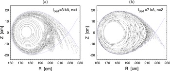
In a number of discharges the effect of the DED of the TEXTOR (see § 5.2 of the Supplementary Part) on the RE generation has been studied. It was found that the RMPs do not completely eliminate the RE formation, but they can increase the decay rate
 $\langle \text{d}I_{p}/\text{d}t\rangle$
and decrease
 $I_{p}^{(RE)}$
. This effect depends on the operational mode
 $n$
, the amplitude of the DED current
 $I_{DED}$
, and the time
 $t_{max}$
when the maximal DED current is reached. As seen from table 1, the maximal effect is obtained when the maximal
 $I_{ded}$
is reached before the gas injection at
 $t=2.0~\text{s}$
, i.e.
 $t_{max}\leqslant t=2.0~\text{s}$
. However, at
 $t_{max}>t=2.0~\text{s}$
the RMPs do not affect it at all or it is very weak. Other experimental observations in the TEXTOR also confirm these observations (Koslowski et al.
Reference Koslowski, Zeng, Lehnen, Lvovskiy and Wongrach2014). We will discuss this problem in § 7.2.
3. Formation of a confined plasma beam
3.1. Main conjecture
It is believed that the plasma disruption is caused by a large-scale magnetic stochasticity of field lines due to interactions of nonlinearly destabilized MHD modes (Carreras et al.
Reference Carreras, Hicks, Holmes and Waddell1980; Kadomtsev Reference Kadomtsev1984; Lichtenberg Reference Lichtenberg1984; Fukuyama et al.
Reference Fukuyama, Itoh, Itoh, Tsuji and Lichtenberg1993; Wesson Reference Wesson2004; Kruger et al.
Reference Kruger, Schnak and Sovinec2005; White Reference White2014). The global stochasticity is mainly due to the interactions of coupled MHD modes with low (
 $m,n$
) numbers: (
 $m=1,2,\dots ,n=1,2,\dots$
). The structure of a stochastic magnetic field mainly depends of the amplitudes
 $B_{mn}$
of MHD modes and the radial profile of the safety factor
 $q({\it\rho})$
, where
 ${\it\rho}$
is the minor radius of a magnetic surface. Depending on these parameters, the stochastic magnetic field may fill entirely the plasma region so that the plasma particles are transported out along chaotic magnetic field lines, which leads to stopping of the plasma current. However, at certain conditions the stochastic magnetic field may not extend up to the central plasma region due to the formation of a magnetic barrier by the outermost intact magnetic surface at
 ${\it\rho}_{c}$
. The electrons confined by this magnetic surface are accelerated by the toroidal electric field induced by the current decay from the outer plasma region, thus forming a RE beam. Let
 $I_{p}({\it\rho})$
be the plasma current flowing inside the magnetic surface of radius
 ${\it\rho}$
,
 $$\begin{eqnarray}I_{p}({\it\rho})=2{\rm\pi}\int _{0}^{{\it\rho}}j_{{\it\varphi}}({\it\rho}){\it\rho}\,\text{d}{\it\rho},\end{eqnarray}$$
where
 $j_{{\it\varphi}}({\it\rho})$
is the toroidal current density profile. Then the initial RE current
 $I_{p}^{(RE)}$
is mainly determined by the pre-disruption plasma current distribution
 $I_{p}({\it\rho})$
confined by the intact magnetic surface
 ${\it\rho}_{c}$
, i.e.
 $I_{p}^{(RE)}\approx I_{p}({\it\rho}_{c})$
.
As will be shown in §§ 6 and 7, the decay of the RE beam mainly depends on two effects: the outward drift of RE orbits induced by the toroidal electric field
 $E_{{\it\varphi}}$
and their resonant interactions with helical magnetic perturbations. The outward drift velocity
 $v_{dr}$
is determined by
 $E_{{\it\varphi}}$
and the RE current
 $I_{p}^{(RE)}$
(see (6.2) and figure 15; see also Abdullaev Reference Abdullaev2015),
 $$\begin{eqnarray}v_{dr}\propto E_{{\it\varphi}}/I_{p}^{(RE)}\propto E_{{\it\varphi}}/{\it\rho}_{c}^{2}.\end{eqnarray}$$
The most stable RE beams are expected to form when the corresponding drift velocity is lowest and the low-order rational magnetic surfaces within the RE beam are absent or there is only one.
3.2. Possible generic structures of stochastic magnetic fields
Below we study possible structures of the stochastic magnetic field which may lead to the formation of the RE beams. We consider two types of the safety factor profiles of
 $q({\it\rho})$
: (i) the monotonic radial profile and (ii) the non-monotonic radial profile, corresponding to the plasmas with the reversed magnetic shear.
The models for the radial profiles of the plasma current
 $I_{p}({\it\rho})$
, the safety factor
 $q({\it\rho})$
of the pre-disruption equilibrium plasma, and the MHD magnetic perturbations are given in § 3 of the Supplementary Part. The perturbation magnetic field simulating low-mode-number MHD modes is given by the toroidal component of the vector potential
 $$\begin{eqnarray}\displaystyle & \displaystyle A_{{\it\varphi}}^{(1)}(R,Z,{\it\varphi},t)=-\frac{R_{0}^{2}}{R}\mathop{\sum }_{mn}m^{-1}a_{mn}({\it\rho})\cos (m{\it\vartheta}-n{\it\varphi}+{\it\Omega}_{mn}t), & \displaystyle\end{eqnarray}$$
 $$\begin{eqnarray}\displaystyle & a_{mn}({\it\rho})=B_{mn}U_{mn}({\it\rho}), & \displaystyle\end{eqnarray}$$
 $B_{mn}$
and rotation frequencies
 ${\it\Omega}_{mn}$
. Here
 $B_{0}$
is the toroidal field strength,
 $R_{0}$
is the major radius
 $R_{0}$
, and the functions
 $U_{mn}({\it\rho})$
describe the radial profiles of the modes.
One should note that the structure of the magnetic field lines in the presence of magnetic perturbations is less sensitive to the radial profiles of
 $U_{mn}({\it\rho})$
. It is mainly determined by the safety factor profiles and the mode amplitudes
 $a_{mn}({\it\rho})$
at the resonant surfaces
 ${\it\rho}={\it\rho}_{mn}$
,
 $q({\it\rho}_{mn})=m/n$
(see § 7.2 of the Supplementary Part).
Monotonic radial profile of
 $q({\it\rho})$
: the case
 $q(0)<1$
. The typical TEXTOR plasma has the monotonic safety factor profile with the value
 $q(0)<1$
at the magnetic axis
 ${\it\rho}=0$
. In this plasma, the
 $m/n=1/1$
mode should play an important role in the structure of stochastic field lines near the plasma centre. At low amplitudes of this mode the global stochastic field lines may not reach the
 $q=1$
magnetic surface and may form a confined region about the plasma centre where REs can be generated. At high amplitudes of the
 $m/n=1/1$
mode the stochastic field lines may cover the entire plasma region with no confined particles.
As was mentioned above, in the TEXTOR experiments plasma disruptions with REs were deliberately caused by the injection of Ar gas while the RE-free disruptions are triggered by He/Ne injection. Experiments show that the penetration lengths of atoms depend on their atomic weights (Bozhenkov et al.
Reference Bozhenkov, Lehnen, Finken, Jakubowski, Wolf, Jaspers, Kantor, Marchuk, Uzgel, VanWassenhove, Zimmermann and Reiter2008): He (or Ne) atoms penetrate deeper into plasma than argon atoms. The injection of these gases may finally give rise to different spectra of amplitudes of MHD modes. One can expect that the amplitude of the
 $m/n=1/1$
MHD mode excited by the He/Ne injection is higher than in the case of argon gas injection.
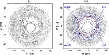
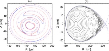
The two possible distinct generic structures of a stochastic magnetic field before the CQ with the RE-free discharge and with the RE discharge are shown in figure 5(a,b) by the Poincaré sections of magnetic field lines. It is assumed that the perturbation field contains several MHD modes:
 $m/n=1/1$
,
 $m/n=2/1$
,
 $m/n=3/2$
, and
 $m/n=5/2$
. In the case shown in figure 5(a), the normalized mode amplitudes
 $b_{mn}=B_{mn}/B_{0}$
are
 $(1,1,1,1)\times {\it\epsilon}_{MHD}$
, and in figure 5(b) they are
 $(1/2,1,1,1)\times {\it\epsilon}_{MHD}$
. The toroidal field magnitude is
 $B_{0}=2.5~\text{T}$
and the dimensionless perturbation parameter
 ${\it\epsilon}_{MHD}=10^{-4}$
. As seen from figure 5(a), for the larger amplitude of the
 $m/n=1/1$
mode the stochastic magnetic field extends up to the central plasma region destroying the separatrix of the
 $m=n=1$
island. For the low amplitude of the
 $m/n=1/1$
mode shown in figure 5(b), the stochastic magnetic field does not reach the
 $q=1$
magnetic surface and covers the region outside the
 $q=1$
magnetic surface. The last intact magnetic surface
 ${\it\rho}_{c}$
(red curve) is located between the resonant surfaces
 $q({\it\rho}_{1})=1$
and
 $q({\it\rho}_{3})=4/3$
(blue curves).
Poincaré sections of magnetic field lines in a pre-disruption plasma caused by several MHD modes: (a) the mode amplitudes
 $b_{mn}=B_{mn}/B_{0}$
are
 $(1,1,1,1)\times {\it\epsilon}_{MHD}$
; (b)
 $b_{mn}=B_{mn}/B_{0}$
are
 $(0.5,1,1,1){\it\epsilon}_{MHD}$
. Red curve corresponds to the last intact magnetic surface, blue curves are the resonant magnetic surfaces
 $q=1$
,
 $q=4/3$
,
 $q=3/2$
, and
 $q=2$
, respectively. The dimensionless perturbation parameter
 ${\it\epsilon}_{MHD}=1.5\times 10^{-4}$
. The plasma current is
 $I_{p}=0.35~\text{MA}$
, the toroidal field is
 $B_{0}=2.5~\text{T}$
, and the safety factor at the magnetic axis is
 $q(0)=0.8$
.

As seen from figure 5, particles in the plasma core are confined by intact magnetic surfaces located between resonant surfaces
 $q=4/3$
and
 $q=1$
. A plasma beam confined in this area is relatively stable. It contains only the
 $m/n=1/1$
MHD mode, which does not lead to a global stochasticity. The radial transport of particles from the confined area can take place only due to small-scale turbulent fluctuations and therefore it has a much smaller rate than those in the stochastic zone. The confinement time of these electrons is sufficiently long enough for them to be accelerated by the inductive electric field, thus creating a RE beam. The modelling of the current of this confined plasma will be discussed in § 5.
Monotonic radial profile of
 $q({\it\rho})$
: the case
 $q(0)>1$
. In this case the
 $m/n=1/1$
mode does not play a significant role in the formation of the stochastic zone in the plasma centre. However, the
 $m/n$
modes with
 $n\geqslant 3$
contribute greatly to the growth of the stochastic zone and shrinkage of the intact magnetic surface
 ${\it\rho}_{c}$
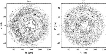
. The examples of such stochastic magnetic fields are shown in figure 6(a,b) corresponding to the values
 $q(0)=1.1$
and
 $q(0)=1.2$
, respectively.
The same as in figure 5 but for the case
 $q(0)>1$
: (a)
 $q(0)=1.1$
; (b)
 $q(0)=1.2$
. It is assumed that the magnetic perturbation contains the
 $m/n$
modes (
 $n=1{-}3$
,
 $m=1{-}8$
) with equal amplitudes. The dimensionless perturbation parameter
 ${\it\epsilon}_{MHD}=1.0\times 10^{-4}$
. The plasma parameters are the same as in figure 5.

The outward drift velocity
 $v_{dr}$
of such RE beams is significantly larger than the one in the case
 $q(0)<1$
. This is because of the smaller RE beam radius
 ${\it\rho}_{c}$
and the higher toroidal electric field
 $E_{{\it\varphi}}$
. Such RE beams decay in shorter times.
Plasma with reversed magnetic shear. In this case the safety factor
 $q({\it\rho})$
has a minimal value located at the normalized radius
 ${\it\rho}_{m}/a\sim 0.4{-}0.6$
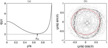
and increases towards the centre and the plasma edge. Figure 7(a,b) show an example of the non-monotonic radial profile of the safety factor
 $q({\it\rho})$
and the corresponding Poincaré section of stochastic magnetic field lines (a more detailed description of this case is given in § 7.3 of the Supplementary Part). The intact magnetic surface located near the shearless magnetic surface (red curve), i.e. the magnetic surface with a minimal value of the safety factor
 $q({\it\rho})$
, is not broken even at the relatively large magnetic perturbations. And, it confines electrons in the central plasma region.
(a) Radial profiles of the safety factor
 $q({\it\rho})$
in the plasma with the reversed magnetic shear. (b) Poincaré sections of magnetic field lines in a pre-disruption plasma caused by several MHD modes. Red curve corresponds to the shearless magnetic surface.

Due to the relatively large confined area, the RE beam would carry a large current
 $I_{p}^{(RE)}$
. According to (3.2), the decay rate of this RE beam owing to the outward drift would be small. This effect probably explains the large RE current with a long lifetime observed in the TFTR tokamak during the disruption of plasmas with the reversed magnetic shear (Fredrickson et al.
Reference Fredrickson, Bell, Taylor and Medley2015).
3.3. Experimental evidences
Existence of the finite interval of the RE currents
 $I_{p}^{(RE)}$
. It follows from the conjecture above that the RE current
 $I_{p}^{(RE)}$
is mainly determined by the current distribution
 $I_{p}({\it\rho})$
in the pre-disruption plasma confined by the intact magnetic surface
 ${\it\rho}_{c}$
, i.e.
 $I_{p}^{(RE)}\approx I_{p}({\it\rho}_{c})$
. Since
 ${\it\rho}_{c}$
is located between the magnetic surfaces
 ${\it\rho}_{1}$
and
 ${\it\rho}_{3}$
corresponding to
 $q({\it\rho}_{1})=1$
and
 $q({\it\rho}_{3})=4/3$
, the RE current
 $I_{p}^{(RE)}$
should be in a finite range. This expectation is in line with the experimental data presented in figure 4. One can see that the range of stable
 $I_{p}^{(RE)}$
values shown in figure 4(b) corresponds well to the space between resonant magnetic surfaces with
 $q({\it\rho}_{1})=1$
and
 $q({\it\rho}_{3})=4/3$
(or
 $q({\it\rho}_{2})=3/2$
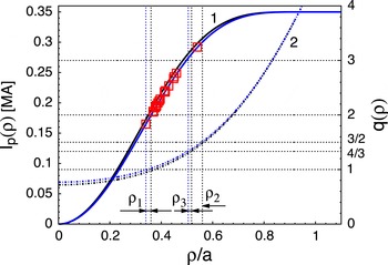
). In figure 8, the radial profile of the pre-disruption plasma current
 $I_{p}({\it\rho})$
and the corresponding safety factor profile
 $q({\it\rho})$
are plotted. Also, values of
 $I_{p}^{(RE)}$
found in other experiments on TEXTOR, see Zeng et al. (Reference Zeng, Koslowski, Liang, Lvovskiy, Lehnen, Nicolai, Pearson, Rack, Jaegers, Finken, Wongrach and Xu2013), lie in the same range.
Radial profile of the plasma current
 $I_{p}({\it\rho})$
(3.1) (solid curves 1 on left-hand side axis) and the corresponding safety factor profile
 $q({\it\rho})$
(dotted curves 2 on right-hand side axis). The rectangular (red) dots correspond to the experimentally measured values of
 $I_{p}^{(RE)}$
for several TEXTOR discharges. The plasma parameters are
 $I_{p}=350~\text{kA}$
,
 $B_{0}=2.4~\text{T}$
,
 $R_{0}=1.75~\text{m}$
, and
 $a=0.46~\text{m}$
. The values of
 $q_{0}=q(0)$
are 0.75 and 0.8, respectively. The radii
 ${\it\rho}_{1}$
,
 ${\it\rho}_{2}$
, and
 ${\it\rho}_{3}$
are the positions of the rational magnetic surfaces
 $q({\it\rho}_{1})=1$
,
 $q({\it\rho}_{2})=3/2$
, and
 $q({\it\rho}_{3})=4/3$
, respectively.

Since the
 $q$
-value on the plasma axis
 ${\it\rho}=0$
is one of the major causes for uncertainties in the
 $q({\it\rho})$
-profile, in figure 8 we show
 $I$
and
 $q$
profiles for
 $q(0)=0.75$
and
 $q(0)=0.8$
. These are in the range of
 $q(0)$
-values experimentally measured between sawtooth crashes in the TEXTOR tokamak (Soltwisch and Stodiek Reference Soltwisch and Stodiek1987; Soltwisch et al.
Reference Soltwisch, Stodiek, Manickam and Schlüter1987) (see also Wesson (Reference Wesson2004, p. 372)). The values of
 $q(0)$
measured after pellet injection in the DIII-D tokamak experiments are also close to these values (Izzo et al.
Reference Izzo, Humphreys and Kornbluth2012). Thus, small changes in
 $q(0)$
still keep the RE currents
 $I_{p}^{(RE)}$
in the interval
 ${\it\rho}_{1}<{\it\rho}<{\it\rho}_{3}$
. The highest and lowest values of
 $I_{p}^{(RE)}$
shown in figure 8 corresponding to the discharges nos 117 859 and 120 140, respectively, lie at the border of the region
 ${\it\rho}_{1}<{\it\rho}<{\it\rho}_{3},{\it\rho}_{2}$
. They have the shortest duration time for the RE current decay (see table 1 and figures 1
b and 4). The presence of several low-order
 $m/n=4/3$
,
 $m/n=3/2$
, and
 $m/n=1/1$
resonant magnetic surfaces within the RE beam may lead to excitations of the corresponding MHD modes. The interactions of these modes may lead to the quick loss of REs due to the formation of a stochastic zone at the edge of the RE beam (see § 7).
Dependence on the level of magnetic perturbations. The existence of the intact magnetic surface
 ${\it\rho}_{c}$
between the
 $q=1$
and
 $q=5/4$
(or
 $q=4/3$
) rational magnetic surfaces and its location depend on the level of the magnetic perturbation
 ${\it\epsilon}_{MHD}$
(more exactly, on the spectrum
 $B_{mn}$
). With increase of
 ${\it\epsilon}_{MHD}$
the radius
 ${\it\rho}_{c}$
shrinks and it can be broken at a certain critical perturbation level
 ${\it\epsilon}_{cr}$
. It leads to the total destruction of the confinement of plasma particles. This is in agreement with experimental observations on the existence of a critical magnetic perturbation level above which the runaway beams are not formed (Zeng et al.
Reference Zeng, Koslowski, Liang, Lvovskiy, Lehnen, Nicolai, Pearson, Rack, Jaegers, Finken, Wongrach and Xu2013).
The shrinkage of
 ${\it\rho}_{c}$
with increasing magnetic perturbation
 ${\it\epsilon}_{MHD}$
leads to the decrease of the RE current
 $I_{p}^{(RE)}$
, since
 $I_{p}^{(RE)}\approx I_{p}({\it\rho}_{c})$
. On the other hand, if one assumes that the plasma current decay is caused by the radial transport of particles in the stochastic magnetic field, its decay rate
 $\text{d}I_{p}/\text{d}t$
should be proportional to the square of the magnetic perturbation level
 ${\it\epsilon}_{MHD}$
,
 $|\langle \text{d}I_{p}/\text{d}t\rangle |\propto |{\it\epsilon}_{MHD}|^{2}$
(see § 4.2). Therefore, one expects that the higher values of
 $|\langle \text{d}I_{p}/\text{d}t\rangle |$
correspond to the lower values of the RE current
 $I_{p}^{(RE)}$
. This expectation is in agreement with the experimental values of these quantities presented in figure 4(a).
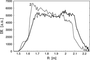
Synchrotron radiation pattern. The formation of the RE beam inside the intact magnetic surface can also be confirmed by the spatial profiles of the synchrotron radiation of high-energy REs with energies exceeding 25 MeV. Figure 9 shows the radial profiles of infrared radiation of the REs at the equatorial plane
 $z=0$
for the two TEXTOR discharges. One can see that radiation is localized inside a finite radial extent corresponding to the central region of the plasma within the
 $q=4/3$
magnetic surface (see figure 5
b). One should note that the radiation from the plasma edge regions,
 $1.5\lesssim R\lesssim 1.6$
and
 $2.1\lesssim R\lesssim 2.2$
, is due to thermal radiation of the wall elements. The outward shift of the radiation pattern is explained to some extent by the drift of RE beams discussed in § 6.1.
Radial profiles of the synchrotron radiation at the equatorial plane
 $z=0$
: curve 1 corresponds to the discharge no. 117 507 at the time instant
 $t=2.034324~\text{s}$
and curve 2 to no. 120 134 at
 $t=2.050284~\text{s}$
.

Another indication of the formation of a confined plasma beam is the rise of the temperature at the initial stage of the beam formation, as seen in the ECE signals shown in figure 1(a,b). It may occur due to the ohmic heating of confined plasma by the induced toroidal electric field or by superthermal emission from high-energy electrons. As thermal electrons are converted into runaway ones, the beam temperature goes down.
4. Thermal and current quench stages
Our analysis in § 2.1 reveals that both the processes induced directly by injected atoms and strong radial transport along stochastic magnetic field lines created by MHD perturbations can lead to heat losses from the plasma in the TQ stage of disruption. During this stage the temperature drops on a time scale of several hundreds of microseconds; the current decay time is 4–6 ms in RE-free discharges and increases up to 0.1 s in discharges with RE generations.
As one can see in figure 1, the CQ stage before the formation of RE beams coincides well with the time interval where magnetic perturbations are significant and the particle transport in a stochastic magnetic field leads to the current decay. To study these processes, we use the models for stochastic magnetic field and collisional transport of test particles described in § 7 of the Supplementary Part.
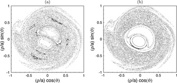
Figure 10(a,b) show the typical Poincaré sections of field lines of this model in the runaway-free disruption case (a) and the case with RE generation (b). The perturbation amplitudes
 ${\it\epsilon}_{mn}$
of all MHD modes, except the
 $(m=1,n=1)$
mode, correspond to a twice larger value of
 ${\it\epsilon}_{MHD}$
than the case shown in figure 5. For the
 $(m=1,n=1)$
mode
 ${\it\epsilon}_{mn}$
corresponds to the same value of
 ${\it\epsilon}_{MHD}$
. The relation between
 ${\it\epsilon}_{mn}$
and
 ${\it\epsilon}_{MHD}$
is
 ${\it\epsilon}_{mn}={\it\epsilon}_{MHD}b_{mn}/{\it\Psi}_{a}$
, where
 ${\it\Psi}_{a}$
is the toroidal magnetic flux at the plasma edge (see § 7 of the Supplementary Part).
Poincaré sections of field lines in a pre-disruption plasma caused by several MHD modes: (a) runaway-free discharges; (b) with REs. The dimensionless MHD mode amplitudes are
 ${\it\epsilon}_{mn}=8.68\times 10^{-3}b_{mn}$
with
 $b_{mn}=1$
for all modes in (a), and
 $b_{11}=1/4$
,
 $b_{mn}=1$
for all other modes (
 $n=1,2$
,
 $m=1{-}5$
) in (b). The safety factor at the magnetic axis is
 $q(0)=0.8$
and at the plasma edge
 $q_{a}=4.7$
.

In general, the transport of heat and particles in the presence of RMPs is a three-dimensional problem. Particularly, a stochastic magnetic field with the topological structures like ones in figure 10 leads to poloidally and toroidally localized heat and particle deposition patterns on the wall (Kruger et al. Reference Kruger, Schnak and Sovinec2005). This is a general feature of open chaotic systems, which has been observed in ergodic divertor tokamaks (see e.g. Finken et al. Reference Finken, Abdullaev, Jakubowski, Lehnen, Nicolai and Spatschek2005; Jakubowski et al. Reference Jakubowski, Schmitz, Abdullaev, Brezinsek, Finken, Krämer-Flecken, Lehnen, Samm, Spatschek, Unterberg and Wolf2006 and Abdullaev Reference Abdullaev2014). The problem can be simplified when we are interested only in the radial transport rate. It can be done by introducing the radial diffusion coefficient averaged over a poloidal angle.
4.1. Heat transport
The electron heat conductivity in a stochastic magnetic field has been assessed by diverse approaches. We apply here the following formula for the electron heat diffusion
 ${\it\chi}_{r}$
deduced on the basis of simulations for transport of test particles, by taking into account coulomb collisions with background plasma species (Abdullaev Reference Abdullaev2013) (see also § 10.4 in Abdullaev Reference Abdullaev2014):
 $$\begin{eqnarray}{\it\chi}_{r}({\it\rho},T_{e})=\frac{v_{\Vert }D_{FL}({\it\rho})}{1+L_{c}/{\it\lambda}_{mfp}},\end{eqnarray}$$
where
 $v_{\Vert }\approx v_{T_{e}}=1.33\times 10^{7}\,T_{e}^{1/2}$
is the thermal velocity of electrons,
 $D_{FL}({\it\rho})$
is the diffusion coefficient of field lines (
 $D_{FL}({\it\rho})\sim 10^{-5}{-}10^{-4}~\text{m}$
),
 ${\it\lambda}_{mfp}=8.5\times 10^{21}\,T_{e}^{2}({\it\rho})/n({\it\rho})$
is the mean free path length of electrons with the temperature
 $T_{e}$
and density
 $n({\it\rho})$
measured in keV and
 $\text{m}^{-3}$
, respectively, and
 $L_{c}\approx {\rm\pi}q({\it\rho})R_{0}$
is the characteristic connection length.
A characteristic heat diffusion time one can estimate as
 ${\it\tau}_{H}=a^{2}/2{\it\chi}_{r}$
, where for
 ${\it\chi}_{r}$
we assume its magnitude at the radial position
 ${\it\rho}=0.566a$
. Before the disruption, the local temperature here is 0.6 keV. This provides
 ${\it\chi}_{r}=287~\text{m}^{2}~\text{s}^{-1}$
and
 ${\it\tau}_{H}=3.68\times 10^{-4}~\text{s}$
, i.e. of the order of the experimentally observed time, for the plasma temperature drop during the TQ after disruption.
For a quantitative analysis, we have modelled the time evolution of the radial profile for the electron temperature averaged over the poloidal
 ${\it\theta}$
and toroidal
 ${\it\varphi}$
angles,
 $T({\it\rho},t)$
. This is done by solving numerically the following diffusion equation:
 $$\begin{eqnarray}\frac{\partial T}{\partial t}=\frac{1}{{\it\rho}}\frac{\partial }{\partial {\it\rho}}\left[{\it\rho}{\it\chi}_{r}({\it\rho},T)\frac{\partial T}{\partial {\it\rho}}\right],\end{eqnarray}$$
where the heat diffusivity is given by (4.1) and the applied boundary conditions are:
 $\partial T({\it\rho})/\partial {\it\rho}=0$
at
 ${\it\rho}=0$
and
 $\partial T({\it\rho})/\partial {\it\rho}=-T/{\it\delta}_{T}$
at the plasma edge
 ${\it\rho}=a$
, where
 ${\it\delta}_{T}\simeq 0.1~\text{m}$
is the characteristic
 $e$
-folding length for the temperature decay in the scrape-off layer.
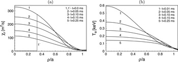
Below we consider an example of heat transport in a fully chaotic magnetic field shown in figure 10(a). Figure 11(a,b) show the radial profiles of the heat conductivity and the temperature at different times. One can see in this case that the temperature drops and almost flattens within a time interval of order 0.5 ms.
Radial profiles of the electron heat conductivity
 ${\it\chi}_{r}({\it\rho},t)$
computed according to (4.1), (a), and of the electron temperature averaged over toroidal and poloidal angles,
 $T_{e}({\it\rho},t)$
, found by solving the heat conduction equation (4.2) numerically, (b), at different time moments after the disruption initiation.

In the situation with a partially stochastic magnetic field, see figure 10(b), anomalous turbulent transport in the very plasma core,
 ${\it\rho}\leqslant 0.3$
, with intact magnetic surfaces is two orders of magnitude smaller than in the outer region. In this case the temperature drop in the central plasma region could be explained by the effect of parallel transport in the magnetic island created by the
 $m/n=1/1$
MHD mode and some level of stochastization in a thin layer near the island separatrix (see a review by Schüller Reference Schüller1995 for more details).
4.2. Current quench stage
As was discussed in § 3.3, the current decay rate
 $\langle \text{d}I_{p}/\text{d}t\rangle$
depends on the initial RE current
 $I_{p}^{(RE)}$
, which in turn depends on the level of magnetic perturbations. Therefore, one can assume that the current decay rate
 $\langle \text{d}I_{p}/\text{d}t\rangle$
may implicitly depend on the level of magnetic perturbations. This assumption, however, may contradict the traditional view that the current decay rate is determined by the time
 ${\it\tau}_{CQ}=R/L$
, i.e. by the ratio of the plasma resistivity
 $R$
to its inductance
 $L$
:
 $\text{d}I_{p}/\text{d}t=-I_{p}/{\it\tau}_{CQ}$
. In the simplest case when
 $R$
and
 $L$
are constants, it leads to the exponential decay law
 $I_{p}(t)\propto \exp (-t/{\it\tau}_{CQ})$
. However, in many tokamaks, particularly in the TEXTOR tokamak, the current decay evolution is better fitted by the linear function
 $I_{p}=a-bt$
rather than by the exponential function (see figure 3). At present, the reason for such a dependence is not quite clear. So, other mechanisms may also play a role in the CQ (see e.g. Kadomtsev Reference Kadomtsev1984; Gerhardt et al.
Reference Gerhardt and Menard2009; Shibata et al.
Reference Shibata, Watanabe, Ohno, Okamoto, Isayama, Kurihara, Nakano, Oyama, Kawano, Matsunaga, Sakakibara, Sugihara and Kamada2010 and references therein).
Particularly, one cannot exclude that the poloidal and toroidal variations of the plasma current imposed by the initial MHD modes in the TQ stage do not disappear immediately with the temperature drop (see also § 5 and (5.1) and (5.5)). This leads to the corresponding variations of the poloidal magnetic field, which acts as non-axisymmetric magnetic perturbations. Below we discuss a possible role of the radial transport of particles in a stochastic magnetic field created by such magnetic perturbations.
The magnetic field structure before the CQ has been assumed similar to the one shown in figure 10. The level of magnetic perturbations may be different from that during and after the TQ when strong magnetic fluctuations are present; see figure 1(d).
One should note that according to the mechanism of RE beam formation discussed above in § 3.1, at the CQ stage the plasma current is carried mainly by thermal electrons. The contribution of REs to the plasma current at this stage is still small. Those REs created outside the outermost intact magnetic surface
 ${\it\rho}_{c}$
are quickly lost due to the fast transport along chaotic field lines. Electrons in the central plasma region
 ${\it\rho}<{\it\rho}_{c}$
confined by the outermost intact magnetic surface are sources for the RE beam.
The time scale of the current decay is determined by the rate of radial particle transport in a stochastic magnetic field. This process has an ambipolar nature and it is strongly collisional due to the low plasma temperature. On the other hand, one expects that the toroidal electric field induced by the current decay also strongly affects the particle transport. Below we give a rough estimation of the particle transport rate based on the collisional test particle transport model.
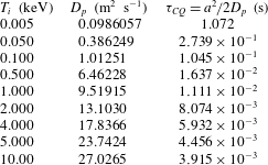
In table 2, we have listed the ambipolar diffusion coefficients
 $D_{p}$
and the characteristic diffusion times
 ${\it\tau}_{CQ}$
of particles at the different plasma temperatures in a stochastic magnetic field shown in figure 10. The typical plasma temperature after the TQ is about from 5 to 50 eV. The average particle confinement time
 ${\it\tau}_{CQ}$
at this temperature changes from 1 to 0.3 s. These time scales are shortened if the magnetic perturbation level
 ${\it\epsilon}^{2}$
is larger. Since the diffusion coefficient
 $D_{p}\propto {\it\epsilon}^{2}$
and therefore
 ${\it\tau}_{CQ}\propto {\it\epsilon}^{-2}$
,
 ${\it\tau}_{CQ}$
can be reduced to one order smaller value for three times larger perturbation than in figure 10. This time scale is still much longer than the experimentally observed values. However, this collisional model does not take account of the effect of the inductive toroidal electric field. One expects that the acceleration of electrons and ions by the electric field increases the radial transport of particles. To include this effect in the collisional model, one can assume that the effective temperature of the plasma is higher than the measured one. The particle diffusion time
 ${\it\tau}_{CQ}$
for the effective temperature 2 keV is about
 $8\times 10^{-3}~\text{s}$
. This time scale gives the average current decay rate
 $|\text{d}I_{p}/\text{d}t|\approx {\rm\Delta}I_{p}/{\it\tau}_{CQ}\sim I_{p}^{(0)}/{\it\tau}_{CQ}=0.35~\text{MA}/(8.0\times 10^{-3}~\text{s})\approx 44.0~\text{MA}~\text{s}^{-1}$
, which is of the order of the experimental measured rates given in table 1. (Here
 $I_{p}^{(0)}$
is the full pre-disruption plasma current.)
Ambipolar diffusion coefficients
 $D_{p}$
of particles and the diffusion times
 ${\it\tau}_{CQ}=a^{2}/2D_{p}$
from the stochastic zone at the different effective plasma temperatures. The plasma radius
 $a=0.46~\text{m}$
.

A more rigorous approach to the particle transport in a stochastic magnetic field during the current decay stage would require a three-dimensional treatment of the problem. It should take into account not only the formation of the ambipolar electric potential (Spizzo et al. Reference Spizzo, Vianello, White, Abdullaev, Agostini, Cavazzana, Ciaccio, Puiatti, Scarin, Schmitz, Spolaore and Terranova2014) but also the inductive toroidal electric field which accompanies the process. The latter may lead to the directionality of the particle transport that eventually may influence the random vertical displacement of runaway beams. Of course, the study of these complicated processes is beyond the scope of the present work.
5. Modelling of post-disruption plasma
The described scenario of plasma disruption with a RE beam allows one to model a post-disruption plasma. After establishing the runaway beam the current is localized inside the area enclosed by the last intact magnetic surface. In general, the distribution of the current density
 $j$
would depend not only on the radial coordinate
 ${\it\rho}$
but also vary along the poloidal
 ${\it\theta}$
and the toroidal
 ${\it\varphi}$
angles due to the presence of the
 $m/n=1/1$
magnetic island. In such a post-disruption plasma the toroidal current density can be presented as a sum of two parts,
 $$\begin{eqnarray}j_{{\it\varphi}}({\it\rho},{\it\theta},{\it\varphi})=j_{0}({\it\rho})+j_{1}({\it\rho},{\it\theta},{\it\varphi}),\end{eqnarray}$$
where
 $j_{0}({\it\rho})$
is the current density depending only on the radial coordinate
 ${\it\rho}$
and
 $j_{1}({\it\rho},{\it\theta},{\it\varphi})$
is the helical current, which is a periodic function of the poloidal
 ${\it\theta}$
and toroidal
 ${\it\varphi}$
angles.
The radial dependence of
 $j_{0}({\it\rho})$
can also be modelled by assuming that after the disruption the current is uniformly distributed over the confined area with a steep gradient at the beam edge
 ${\it\rho}_{c}$
. Calculations show that electron orbits do not significantly depend on the specifics of the radial profile of
 $j_{0}({\it\rho})$
. For our calculations of GC orbits, we choose the following profile:
 $$\begin{eqnarray}j_{0}({\it\rho})=\left\{\begin{array}{@{}l@{}}J_{0}\tanh [({\it\rho}_{c}^{2}-{\it\rho}^{2})/{\it\Delta}_{a}],\quad \text{for }{\it\rho}<{\it\rho}_{c},\quad \\ 0,\quad \text{for }{\it\rho}>{\it\rho}_{c},\quad \end{array}\right.\end{eqnarray}$$
where
 $J_{0}$
is a constant determined by the full current of the beam
 $I_{p}^{(RE)}$
and
 ${\it\Delta}_{a}$
is the steepness parameter. The current flowing inside the magnetic surface
 ${\it\rho}$
, i.e.
 $I_{p}({\it\rho})=2{\rm\pi}J_{0}\int _{0}^{{\it\rho}}j_{0}({\it\rho}^{\prime }){\it\rho}^{\prime }\,\text{d}{\it\rho}^{\prime }$
, is given by
 $$\begin{eqnarray}I_{p}({\it\rho})=\left\{\begin{array}{@{}l@{}}\displaystyle I_{p}^{(RE)}\left[1-\frac{\ln \cosh ([{\it\rho}_{c}^{2}-{\it\rho}^{2}]/{\it\Delta}_{a})}{\ln \cosh ({\it\rho}_{c}^{2}/{\it\Delta}_{a})}\right],\quad \text{for }{\it\rho}\leqslant {\it\rho}_{c},\quad \\ I_{p}^{(RE)},\quad \text{for }{\it\rho}>{\it\rho}_{c},\quad \end{array}\right.\end{eqnarray}$$
where
 $I_{p}^{(RE)}$
is the full current of the confined area.
One should also note the fact that after the TQ the plasma beam is shifted inwardly because of drop of plasma pressure. In the modelling this fact can be taken into account by assuming that the radial position of the centre
 $R_{a}$
of the post-disruption plasma is different from the one of the pre-disruption plasma. The safety factor of the corresponding plasma is then given by
 $$\begin{eqnarray}q({\it\rho})=q_{cyl}({\it\rho})C({\it\rho}/R_{a}),\quad q_{cyl}({\it\rho})={\displaystyle \frac{2{\rm\pi}{\it\rho}^{2}B_{0}}{{\it\mu}_{o}R_{a}I_{p}({\it\rho})}},\end{eqnarray}$$
where
 $q_{cyl}({\it\rho})$
is the safety factor of the cylindrical plasma; the function
 $C(x)=1+A_{1}x+A_{2}x^{2}+\cdots \,$
is a function which takes into account the toroidicity of the plasma. The coefficients
 $A_{i},~(i=1,2,\dots )$
depend on the plasma pressure (Abdullaev et al.
Reference Abdullaev, Finken and Spatschek1999; Abdullaev Reference Abdullaev2006).
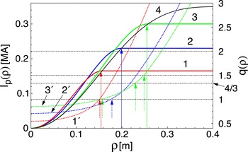
Figure 12 shows the radial profiles of
 $I_{p}({\it\rho})$
(solid curves 1–3 on the left-hand side axis) (5.3) and the safety factor (5.4) (dashed curves
 $1^{\prime }{-}3^{\prime }$
on the right-hand side axis) for the three discharge parameters, respectively. Solid black curve 4 corresponds to the pre-disruption plasma current profile. We set the toroidal field magnitude
 $B_{0}=2.4~\text{T}$
and the beam centre at
 $R_{a}=1.7~\text{m}$
. The plasma radius
 $a$
is found from the condition
 $I_{p0}(a)=I_{p}^{(RE)}$
, where
 $I_{p0}(r)$
is the current profile of the pre-disruption plasma. The vertical dashed colour arrows show the radial positions of the
 $q=1$
,
 $q=4/3$
, and
 $q=3/2$
magnetic surfaces and the vertical solid arrows indicate the plasma radii
 $a$
.
Radial profiles of the plasma current
 $I_{p}({\it\rho})$
(5.3) (solid curves 1–3 on left-hand side axis) and the safety factor profiles
 $q({\it\rho})$
(5.4) (dashed curves
 $1^{\prime }{-}3^{\prime }$
on right-hand side axis); curve 4 corresponds to the pre-disruption plasma current. The red curves 1 and
 $1^{\prime }$
correspond to
 $I_{p}^{(RE)}=165~\text{kA}$
, blue curves 2 and
 $2^{\prime }$
correspond to
 $I_{p}^{(RE)}=230~\text{kA}$
, and green curves 3 and
 $3^{\prime }$
correspond to
 $I_{p}^{(RE)}=300~\text{kA}$
. The vertical solid arrows indicate the radii of the plasma beam
 $a$
, the vertical dashed arrows indicate the positions of resonant magnetic surfaces
 $q=1$
and
 $q=3/2$
. The toroidal magnetic field
 $B_{t}=2.4~\text{T}$
,
 $R_{a}=1.7~\text{m}$
, the pre-disruption plasma current
 $I_{p}=350~\text{kA}$
, and the radius
 $a_{0}=0.46~\text{m}$
.

Note that the red curves 1 and
 $1^{\prime }$
and the green curves 3 and
 $3^{\prime }$
in figure 12 correspond to the discharges with the lowest and highest values of
 $I_{p}^{(RE)}$
shown in figure 1(b). For the lowest value of
 $I_{p}^{(RE)}$
, the radial position of the
 $q=1$
magnetic surface is very close to the RE beam radius
 ${\it\rho}_{c}$
. For the highest value of
 $I_{p}^{(RE)}$
, the magnetic surfaces with
 $q=1$
,
 $q=4/3$
, and
 $q=3/2$
are located inside the plasma region
 ${\it\rho}<a$
. However, the radial position of the magnetic surface
 $q=3/2$
is at the plasma edge. For the typical discharges like the one shown by blue curves, the magnetic surface
 $q=1$
is located relatively far from the plasma edge.
The Fourier expansion of the helical current,
 $j_{1}({\it\rho},{\it\theta},{\it\varphi})$
,
 $$\begin{eqnarray}j_{1}({\it\rho},{\it\theta},{\it\varphi})=\mathop{\sum }_{m,n}j_{mn}({\it\rho})\cos (m{\it\theta}-n{\it\varphi}+{\it\phi}_{mn}),\end{eqnarray}$$
is mainly dominated by the
 $m/n=1/1$
component. This assumption is based on the analysis of numerous disruptions in the JET tokamak (Gerasimov et al.
Reference Gerasimov, Hender, Morris, Riccardo and Zakharov2014).
We should assume that the value of the safety factor at the beam axis
 $q(0)$
is less than unity. This assumption is supported by a number of experimental measurements of the current profile after the sawtooth crashes in the TEXTOR, TFTR, and JET tokamaks (Soltwisch et al.
Reference Soltwisch, Stodiek, Manickam and Schlüter1987; O’Rourke Reference O’Rourke1991; Yamada et al.
Reference Yamada, Livinton, Pomphrey, Budny, Manickam and Nagayama1994; Soltwisch and Koslowski Reference Soltwisch and Koslowski1995; Koslowski et al.
Reference Koslowski, Soltwisch and Stodiek1996; Soltwisch and Koslowski Reference Soltwisch and Koslowski1997).
This model of the post-disruption plasma current describes only the initial stage of the RE beam. During acceleration of electrons in the toroidal electric field the RE orbits drift outward and their form evolves from a circular one to an oval one. This process changes in turn the RE beam form and its current. The self-consistent description of the time evolution of the RE beam is a difficult problem. It is beyond the scope of the present study.
6. Evolution of GC orbits during acceleration
Now we discuss the dynamics of RE orbits during the acceleration of electrons induced by the toroidal electric field in a toroidal post-disruption plasma. Mainly we study the outward drift of RE orbits and its role in the RE losses. However, we will not consider the processes of the generation and the proliferation of the RE population, the problems of stability of RE beams, and related issues. These problems have been much discussed in the literature.
6.1. Outward drift of RE orbits
First we consider the case of an axisymmetric plasma beam neglecting the helical magnetic perturbations. The inductive toroidal electric field generated due to the current decay during the plasma disruption accelerates thermal electrons. This is an adiabatic process, since the characteristic time of significant variation of energy is much larger than the transit time of electrons. Therefore, the GC orbit slowly drifts outward without changing the area of the GC orbit in the poloidal plane, which is an adiabatic invariant
 $J$
, or the action variable (see § 6.1 of the Supplementary Part). With increasing electron energy the topology of GC orbits also slowly changes from the circular one to the oval one. Starting from a certain critical energy
 $E_{cr}$
the adiabaticity of the process breaks and the GC orbit bifurcates by creating an unstable stagnation point (or X-point) inside the plasma region. With the further increase of energy the GC orbit crosses the separatrix (a homoclinic orbit associated with the X-point) and becomes unconfined. The value
 $E_{cr}$
depends on the plasma current
 $I_{p}$
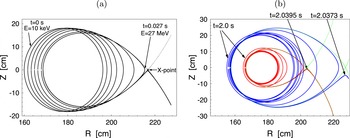
. The described phenomenon is an addition mechanism of confinement loss of REs. Figure 13(a) shows a typical evolution of a GC orbit in the presence of the toroidal electric field with the constant beam current
 $I_{p}=100~\text{kA}$
and the loop voltage
 $V=40~\text{V}$
.
(a) Evolution of the GC orbit of accelerating electrons in the (
 $R,Z$
)-plane at the constant plasma current
 $I_{p}=100~\text{kA}$
in the presence of a constant toroidal electric field with
 $V=40~\text{V}$
. Dashed curve corresponds to the separatrix of GC orbits of the electrons of energy
 $E=27~\text{MeV}$
. (b) The same as in (a) but for the two GC orbits of accelerating electrons for the time-varying current
 $I_{p}(t)$
and the loop voltage
 $V(t)$
corresponding to the TEXTOR discharge no. 117 527. Green curves correspond to the separatrices of GC orbits.

One should note that the formation of the separatrix of RE GC orbits during the acceleration process in tokamaks has been first predicted in Zehrfeld et al. (Reference Zehrfeld, Fussmann and Green1981). The numerical study of this process in a realistic tokamak configuration has been carried out in Wongrach et al. (Reference Wongrach, Finken, Abdullaev, Koslowski, Willi and Zeng2014). Particularly, it was shown that with increasing electron energy the area confined by the separatrix decreases and it vanishes when the energy exceeds a certain critical value
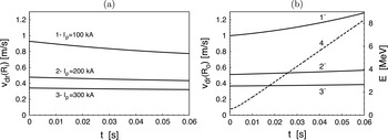
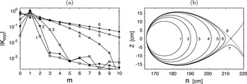
 ${\mathcal{E}}_{cr}$
, i.e. such electrons cannot be confined. The critical energy
 ${\mathcal{E}}_{cr}$
is proportional to the square root of the plasma current
 $I_{p}$
,
 ${\mathcal{E}}_{cr}\propto \sqrt{I_{p}}$
.
The described evolution of RE orbits is in agreement with the experimental observation of the infrared radiation patterns observed in the experiment in the TEXTOR tokamak (Wongrach et al. Reference Wongrach, Finken, Abdullaev, Koslowski, Willi and Zeng2014) and in the DIII-D tokamak (Hollmann et al. Reference Hollmann, Austin, Boedo, Brooks, Commaux, Eidietis, Humphreys, Izzo, James, Jernigan, Loarte, Martin-Solis, Moyer, Muñoz-Burgos, Parks, Rudakov, Strait, Tsui, Van Zeeland, Wesley and Yu2013). The observations clearly show the evolution of the spatial form of RE beams from crescent ones into oval ones with increasing electron energies.
An example of the time evolution of GC orbits in the plasma beam with a time-varying current
 $I_{p}(t)$
and the loop voltage
 $V(t)$
corresponding to the TEXTOR discharge no. 117 527 is shown in figure 13(b). To simplify the calculations of orbits, we have assumed that the loop voltage
 $V(t)$
is uniform in the poloidal section, i.e. it does not depend on the radial coordinate
 $r$
and is equal to the experimentally measured value at the limiter. However, this assumption only approximately describes the situation. To find the exact magnitude of the toroidal electric field during the runaway current decay one should solve the corresponding Maxwell equations.
One of the important parameters of the GC orbit is the effective safety factor
 $q_{eff}$
, defined as a ratio
 $q_{eff}={\rm\Delta}{\it\varphi}/2{\rm\pi}$
, where
 ${\rm\Delta}{\it\varphi}$
is the increment of the toroidal angle
 ${\it\varphi}$
per one poloidal turn. It is a function of the action variable
 $J$
and particle energy
 $E$
. For low-energy electrons the quantity
 $q_{eff}(J,E)$
coincides with the safety factor
 $q({\it\rho})$
of the equilibrium magnetic field. With increasing electron energy the effective safety factor strongly deviates from
 $q({\it\rho})$
. With RE energy
 $E$
approaching the critical one
 $E_{cr}$
it diverges as
 $$\begin{eqnarray}q_{eff}(J,E)\propto -\ln \,|E-E_{cr}|.\end{eqnarray}$$
Figure 14 shows the typical time evolutions of the effective safety factors
 $q_{eff}$
of two GC orbits during the electron acceleration in the conditions of the TEXTOR discharge no. 117 527.
Time evolution of the effective safety factors
 $q_{eff}$
(left-hand side axis) and electron energies (right-hand side axis) during the acceleration in the discharge no. 117 527. Blue curves correspond to the orbit launched at the coordinate (
 $R=160$
,
 $Z=0$
) cm and red curves to the one with (
 $R=165$
,
 $Z=0$
) cm. Horizontal lines correspond to
 $q(t)=m$
, where
 $m=1,2,\dots$
are integers.

Figure 15 shows the time evolution of the outward drift velocity
 $v_{dr}$
calculated numerically for the three different RE beam currents. It is quite well described by the formula derived in Abdullaev (Reference Abdullaev2015) (see also § 4 of the Supplementary Part)
 $$\begin{eqnarray}v_{dr}={\displaystyle \frac{R_{0}E_{{\it\varphi}}}{RB_{z}^{\ast }}}\left(1-\frac{RT_{av}}{R_{0}T}\right),\end{eqnarray}$$
where
 $B_{z}^{\ast }=B_{z}+F(E)$
is the effective poloidal magnetic field,
 $B_{z}$
is the
 $z$
-component of the poloidal magnetic field at the equatorial plane
 $z=0$
, and
 $F(E)$
is a term depending on the particle energy. The quantity
 $$\begin{eqnarray}T_{av}=\frac{2{\rm\pi}q_{eff}R_{0}}{v_{{\it\varphi}}}\end{eqnarray}$$
is the average transit time,
 $E_{{\it\varphi}}$
is the toroidal electric field strength,
 $T$
is the transit time of the orbit, and
 $v_{{\it\varphi}}$
is the toroidal velocity.
Drift velocities of innermost
 $v_{df}(R_{i})$
(a) (curves 1, 2, and 3) and outermost
 $v_{df}(R_{o})$
(b) (curves
 $1^{\prime }$
,
 $2^{\prime }$
, and
 $3^{\prime }$
) points of orbits for the different plasma currents: curves 1 and
 $1^{\prime }$
correspond to the plasma current
 $I_{p}=100~\text{kA}$
, curves 2 and
 $2^{\prime }$
correspond to
 $I_{p}=200~\text{kA}$
, and curves 3 and
 $3^{\prime }$
correspond to
 $I_{p}=300~\text{kA}$
. Curve 4 describes the increase of energy
 $E$
(right-hand axis). The toroidal field
 $B_{t}=2.5~\text{T}$
, major radius
 $R_{0}=175~\text{cm}$
, minor radius
 $a=46~\text{cm}$
, and loop voltage
 $V_{loop}=5~\text{V}$
.

The expression (6.2) describes the creation of the X-point and the separatrix of RE orbits at the critical energy
 $E_{cr}$
. This phenomenon is related with the appearance of zeroes of the effective poloidal magnetic field
 $B_{z}^{\ast }$
at
 $E=E_{cr}$
and a certain radial distance
 $R=R_{s}$
within the plasma region (see Abdullaev Reference Abdullaev2015 for details).
At
 $|B_{z}|\gg |F(E)|$
and
 $T_{av}\approx T$
, the formula (6.2) is reduced to
 $$\begin{eqnarray}v_{dr}=\frac{qE_{{\it\varphi}}}{B_{0}}=-\frac{(R-R_{0})E_{{\it\varphi}}}{RB_{Z}},\end{eqnarray}$$
obtained by Guan et al. (Reference Guan, Qin and Fisch2010) and Qin et al. (Reference Qin, Guan and Fisch2011) for the circular orbits. Here
 $q=(R-R_{0})B_{0}/B_{z}R$
is the safety factor of the magnetic field. As seen from figure 15, the formulas (6.2) and (6.4) give the correct dependence of
 $v_{dr}$
on the plasma current
 $I_{p}$
,
 $v_{dr}\propto I_{p}^{-1}$
, because
 $B_{z}\propto I_{p}$
.
However, the formula (6.4) does not describe the situation when the GC orbits take an oval form with increasing energy similar to the ones shown in figure 13(a,b). From the latter, it follows that the average outward velocity
 $v_{dr}$
of the innermost part of the orbit is approximately equal to 0.6 and
 $8~\text{m}~\text{s}^{-1}$
of the outermost part of the orbit.
6.2. RE current decay
The rate
 $\text{d}I_{p}/\text{d}t$
of the runaway current loss due to the described outward drift of orbits can be roughly estimated as follows. This loss mechanism is mainly caused by the shrinkage of the beam radius
 ${\it\rho}_{c}$
. The rate of such a shrinkage
 $\text{d}{\it\rho}_{c}/\text{d}t$
is of order of the average outward velocity
 $v_{dr}$
. Since
 $I_{p}\propto {\it\rho}_{c}^{2}$
, we have
 $$\begin{eqnarray}\frac{\text{d}I_{p}}{\text{d}t}=\frac{\text{d}I_{p}}{\text{d}{\it\rho}_{c}}\frac{\text{d}{\it\rho}_{c}}{\text{d}t}\sim \frac{2I_{p}}{{\it\rho}_{c}}v_{dr}\propto \frac{E_{{\it\varphi}}}{{\it\rho}_{c}}.\end{eqnarray}$$
For the typical values of
 $I_{p}\approx 0.2~\text{MA}$
,
 ${\it\rho}_{c}\approx 0.2~\text{m}$
, and
 $v_{dr}\sim 1~\text{m}~\text{s}^{-1}$
, one has
 $\text{d}I_{p}/\text{d}t\approx 4~\text{MA}~\text{s}^{-1}$
. This estimation is of order of the experimentally measured average decay rate of the runaway current listed in table 1.
Since the safety factor
 $q$
, as well as
 $q_{eff}$
, of RE beams is about unity,
 $q_{eff}\sim 1$
, the outward drift may slow down for the higher values of the toroidal magnetic field
 $B_{0}$
. However, the much higher toroidal electric field
 $E_{{\it\varphi}}$
may compensate this effect, so that the decay time of RE currents in large tokamaks, like ITER, may have the same order as in smaller tokamaks.
One should also note that the outward drift velocity
 $v_{dr}$
is proportional to the inverse aspect ratio of tokamaks,
 $v_{dr}\propto a/R_{0}$
(Abdullaev Reference Abdullaev2015). It means that the RE current loss due to the outward drift of orbits in spherical tokamaks would be larger than in standard tokamaks, so that the REs would cease faster. This effect could be one of the reasons of the absence of REs during disruptions in NSTX tokamaks (Gerhardt et al.
Reference Gerhardt and Menard2009).
Besides outward orbit drifts, the RE current losses are also caused by the internal MHD mode, which will be discussed in the next section. The collisions of REs with neutral particles may also contribute to the RE losses.
7. Effect of magnetic perturbations
The effect of the magnetic perturbations on electrons in the post-disruption current beam strongly depends on its safety factor profile
 $q({\it\rho})$
, the spectrum of magnetic perturbations, and the electron energy. To explain this effect, we consider a simplified version of GC motion equations in the presence of magnetic perturbations. (A rigorous consideration of this problem is given in § 6 of the Supplementary Part.)
The particle drift motion in the presence of perturbations can be represented by Hamiltonian equations similar to the equations for magnetic field lines,
 $$\begin{eqnarray}\frac{\text{d}{\it\vartheta}}{\text{d}{\it\varphi}}=\frac{\partial K}{\partial J},\quad \frac{\text{d}J}{\text{d}{\it\varphi}}=-\frac{\partial K}{\partial {\it\vartheta}_{z}},\end{eqnarray}$$
with the Hamiltonian
 $K=K({\it\vartheta},J,E,{\it\varphi})$
with the canonical variables
 $({\it\vartheta},J)$
, and the toroidal
 ${\it\varphi}$
as the time-like variable. In the absence of perturbations GC orbits wind around the drift surfaces
 $J=\text{const.}$
and the poloidal angle
 ${\it\vartheta}$
is a linear function of
 ${\it\varphi}$
,
 ${\it\vartheta}={\it\varphi}/q_{eff}(J,E)+{\it\vartheta}$
. In the presence of perturbations the Hamiltonian
 $H$
can be represented as a sum
 $$\begin{eqnarray}K=\int \frac{\text{d}J}{q_{eff}(J,E)}+{\it\epsilon}K_{1}({\it\vartheta}_{z},J,E,{\it\varphi}).\end{eqnarray}$$
Since the perturbations are periodic in poloidal and toroidal angles and in time, it can be represented by a Fourier series
 $$\begin{eqnarray}K_{1}({\it\vartheta}_{z},J,E,{\it\varphi})=\mathop{\sum }_{mn}K_{mn}(J,E)\exp [\text{i}(m{\it\vartheta}-n{\it\varphi})].\end{eqnarray}$$
The strongest influence of perturbations on particles takes place on the (
 $m,n$
) resonant drift surfaces, i.e.
 $$\begin{eqnarray}m=nq_{eff}(J,E),\end{eqnarray}$$
originating from the (
 $m,n$
) term in (7.3) with the amplitude
 $K_{mn}(J,E)$
. They are determined by the magnetic perturbation spectrum
 $b_{mn}$
,
 $$\begin{eqnarray}K_{mn}(J,E)\propto \mathop{\sum }_{m^{\prime }}b_{m^{\prime }n}\int _{0}^{2{\rm\pi}}\,\text{d}{\it\vartheta}\exp [\text{i}(m{\it\vartheta}-m^{\prime }{\it\vartheta}_{M})],\end{eqnarray}$$
where
 ${\it\vartheta}_{M}$
, the poloidal angle associated with magnetic field lines, is a function of
 ${\it\vartheta}$
as well as the particle energy
 $E$
.
For low-energy electrons (up to 5 MeV) the spectrum of amplitudes
 $K_{mn}(J,E)$
weakly depends on energy
 $E$
and is close to the spectrum of magnetic perturbations
 $b_{mn}$
of the
 $(m,n)$
th modes. With increasing energy the spectrum of perturbations
 $K_{mn}(J,E)$
deviates from
 $b_{mn}$
and acquires more higher poloidal harmonics
 $m$
. An example of the poloidal spectra of perturbations
 $K_{mn}(J,E)$
for different particle energies is shown in figure 16(a). The corresponding unperturbed orbits are plotted in figure 16(b). It is assumed that the magnetic perturbation contains a single
 $(m=1,n=1)$
mode. For the low-energy electrons with
 $E<10~\text{MeV}$
, the spectrum
 $K_{mn}$
contains the predominant
 $m=1$
mode.
(a) Spectrum of perturbations
 $K_{mn}$
and (b) corresponding RE orbits with different energies
 $E$
. Curves 1–7 correspond to RE energies 10 keV, 20 MeV, 30 MeV, 40 MeV, 42 MeV, 42.5 MeV, and 42.7 MeV, respectively. Curve 8 corresponds to the separatrix with the critical energy
 $E_{cr}=42.646~\text{MeV}$
. The plasma current
 $I_{p}=150~\text{kA}$
, the toroidal field
 $B_{0}=2.5~\text{T}$
, and the toroidal mode number
 $n=1$
.

With increasing energy the amplitudes
 $K_{mn}$
of higher
 $m$
also grow and the width of the poloidal spectrum
 $K_{mn}$
in
 $m$
becomes wider, as shown in figure 16(b). For the spectrum
 $K_{mn}$
, one can obtain the following asymptotic formula for the orbits close to the separatrix (see § 3.4 in Abdullaev Reference Abdullaev2014)
 $$\begin{eqnarray}K_{mn}\propto \frac{1}{q_{eff}}\exp \left(-\frac{mC}{q_{eff}}\right),\end{eqnarray}$$
where
 $C$
is a finite constant, and the effective safety factor
 $q_{eff}$
diverges as (6.1).
As was shown in § 5 (see also figure 12), the typical values of
 $q({\it\rho})$
vary over
 $q(0)\approx 0.7{-}0.8$
at the magnetic axis and
 $q(a)<1.5$
at the plasma edge. Therefore, the strongest effect of the RMPs on electron orbits may be expected if its spectrum
 $b_{mn}$
contains a sufficient number of
 $(m,n)$
-components that are resonant to the magnetic surfaces with
 $q$
in the interval
 $q(0)<q=m/n<q(a)$
that would create a stochastic zone of magnetic field lines. The electrons from this stochastic layer would then be radially transported to the wall.
Below we discuss the influence of magnetic perturbations on RE orbits for two specific cases. First we consider the effect of an internal single helical magnetic field and then we analyse the effect of the external RMPs, namely, the TEXTOR-DED, on the confinement of REs.
7.1. Effect of a single helical magnetic field
Assume that the magnetic perturbation (3.3) contains the single
 $(m=1,n=1)$
MHD mode, as was proposed in the model of the post-disruption current beam described in § 5. For the low-energy electrons it creates a single island structure, since the deviations of their GC orbits from the magnetic surfaces is small. Such a system is stable because the single MHD mode does not create stochasticity of magnetic field lines. An example of this case is shown in figure 17(a) by the Poincaré sections of RE orbits (red dots) and magnetic field lines (blue dots).
Poincaré sections of RE orbits in the (
 $R,Z$
)-plane: red dots correspond to RE orbits with energies
 $E=1~\text{MeV}$
(a) and
 $E=20~\text{MeV}$
(b). [In (a) blue dots correspond to magnetic field lines, green dots is the separatrix.] The perturbation parameter
 ${\it\epsilon}=10^{-5}$
, the plasma current
 $I_{p}=200~\text{kA}$
(a) and
 $I_{p}=100~\text{kA}$
(b).

With increasing energy of the electrons and decreasing beam current the electrons’ GC orbits strongly deviate from the magnetic field lines. The effective safety factor
 $q_{eff}$
of the GC orbit increases as the electron energy grows, as was shown in figure 14. At certain time instants the value of
 $q_{eff}$
reaches an integer value, so that a resonant condition may be satisfied for the higher harmonics
 $(m>1,n>1)$
of the GC orbits with the
 $(m=1,n=1)$
magnetic perturbation. This generates a number of island chains of GC orbits. The interaction of several such island structures may even lead to the formation of a stochastic layer near the separatrices (see figure 13
a,b).
Figure 17(b) illustrates a typical structure of high-energy electrons in the presence of the internal helical magnetic field with a single
 $(m=1,n=1)$
mode. Such a structure leads to a widening area of loss of electrons and decreasing of the critical energy
 $E_{cr}$
. The characteristic escape time of REs from the stochastic layer is of order of
 $10~{\rm\mu}\text{s}$
. Sudden RE bursts in many discharges is probably related with the loss of REs from the stochastic layer. The occurrence of the MHD mode signals accompanying these events will be discussed in § 7.3.
As was discussed above in §§ 2 and 5 (see also figures 1
b and 12), there are some exceptional discharges (for example no. 117 859) with the highest RE current and several low-order rational surfaces within the plasma beam. Such a beam can be easily destabilized by the magnetic perturbations containing several MHD modes with low-order (
 $m,n$
) numbers. Such a magnetic perturbation may strongly affect the electrons, creating a chaotic zone at the beam edge open to the wall. Such an effect probably explains the sudden loss of REs at certain times seen in figure 1(b).
7.2. Influence of the TEXTOR-DED
The coil configuration of the TEXTOR-DED is designed to have the poloidal spectra of magnetic perturbations localized near the magnetic surface
 $q=3$
of the flat-top plasma discharges (see § 5.2 of the Supplementary Part). Therefore, these perturbations do not contain the necessary number of resonant components to create a stochastic zone of magnetic field lines in the post-disruption current beam with the safety factor
 $q$
lying between
 $q(0)<1$
and
 $q(a)<1.5$
.
In the so-called
 $3/1$
operational mode with the predominant toroidal mode
 $n=1$
there is only one
 $(m=1,n=1)$
component resonant to the magnetic surface
 $q=1$
. A similar situation takes place in the
 $6/2$
mode (
 $n=2$
) with the resonant component
 $(m=2,n=2)$
. (There are no magnetic surfaces in the plasma region that are resonant to the components
 $(m=1,n=2)$
and
 $(m=3,n=2)$
.) On the other hand, this resonant component of the DED field is weak, since it is located away from the maximum of the spectrum. Therefore, the effect of the DED on the RE beam does not create a stochastic zone of magnetic field lines from which electrons would escape to the wall as in the case of the stochastic zone in a flat-top plasma operation. Only the
 $m/n=1/1$
component of the DED perturbations may create an island structure near the
 $q=1$
magnetic surface similar to the one shown in figure 17(a).
With increasing energy of REs and decreasing plasma current the DED perturbation starts to affect the REs because of the appearance of high-mode resonances
 $q_{eff}=m/n$
similar to the case discussed in § 7.1. It generates structures with islands and a stochastic layer. Figure 18(a,b) show the typical Poincaré sections of GC orbits of energetic electrons affected by the TEXTOR-DED: (a) corresponds to the
 $3/1$
mode with the DED current
 $I_{ded}=3~\text{kA}$
; (b) corresponds to the
 $6/2$
mode with
 $I_{ded}=7~\text{kA}$
. The particle energy is taken as
 $E=20~\text{MeV}$
, the plasma current
 $I_{p}=94~\text{kA}$
, and the toroidal field
 $B_{0}=2.5~\text{T}$
. These structures explain the fast decay of RE current in its final stage accompanied by spikes in the scintillation probe (see figure 1
b).
Poincaré sections of RE orbits in the (
 $R,Z$
)-plane of the RE orbits of energy
 $E=20~\text{MeV}$
in the presence of the magnetic perturbations of the TEXTOR-DED. (a) corresponds to the
 $n=1$
mode and the DED current
 $I_{ded}=3~\text{kA}$
; (b) corresponds to the
 $n=2$
mode and
 $I_{ded}=7~\text{kA}$
. The plasma current
 $I_{p}=94~\text{kA}$
and the toroidal field
 $B_{0}=2.4~\text{T}$
.

The structures of RE orbits shown in figures 17(b) and 18 correspond to the final termination stages of RE current. They have features which are characteristic for the so-called stable and unstable manifolds created by the splitting of separatrices (see e.g. Abdullaev Reference Abdullaev2014). They lead to the toroidally and poloidally localized deposition patterns of REs on the wall. Toroidal peaking and spatial–temporal evolution of hard X-ray emission in the final stage of RE current loss observed in DIII-D experiments (James et al. Reference James, Austin, Commaux, Eidietis, Evans, Hollmann, Humphreys, Hyatt, Izzo, Jernigan, La Haye, Parks, Strait, Tynan, Wesley and Yu2012) is consistent with the described topology of REs.
The experimental observations in the TEXTOR-DED have indeed showed that the RMP field, which is switched on just after the TQ, does not affect the radial transport and the loss of low-energy electrons (Koslowski et al. Reference Koslowski, Zeng, Lehnen, Lvovskiy and Wongrach2014; Wongrach et al. Reference Wongrach, Finken, Abdullaev, Willi, Zeng and Xu2015) (see also table 1). This is mainly because of the mentioned features of the poloidal and toroidal spectra of the DED field.
7.3. Generation of magnetic perturbations by high-energy electrons
As mentioned in § 2, the occurrence of the MHD activities during the sudden RE bursts can be explained by the nonlinear interaction of high-energy electrons with the
 $(m=1,n=1)$
MHD mode. The MHD magnetic perturbations with mode numbers
 $(m,n)$
higher than the initial
 $(m=1,n=1)$
mode can be generated during the acceleration process of the REs. At a certain energy of REs their orbits strongly deviate from the magnetic surfaces, which creates in turn higher
 $(m,n)$
-harmonics,
 $(m>1,n>1)$
, of the MHD (
 $m=1,n=1$
) mode (7.5). The resonant interaction of RE orbits with these harmonics leads to the redistribution of the corresponding current near these orbits according to the helicity of these modes. Therefore, the current density (5.5) acquires higher
 $(m,n)$
-components
 $j_{mn}$
, which in turn generates the corresponding MHD modes. The bursts of magnetic activities accompanied by sudden runaway current drops observed in experiments (see figure 1
a,b) are probably related to the described phenomenon.
8. Summary
Based on the analysis of numerous experimental data obtained in the TEXTOR tokamak we have proposed a possible mechanism of the plasma disruption with the formation of RE beams. The plasma disruption starts due to a large-scale magnetic stochasticity caused by nonlinearly excited MHD modes with low
 $(m,n)$
numbers (
 $m/n=1/1,2/1,3/2,5/2,\dots$
). The RE beam is formed in the central plasma region confined by the intact magnetic surface. Its location depends on the safety factor profile
 $q({\it\rho})$
and the spectrum of the MHD modes. In the cases of plasmas with a monotonic profile of
 $q({\it\rho})$
and at a sufficiently small amplitude of the
 $m/n=1/1$
mode the most stable RE beams are formed by the intact magnetic surface located between the magnetic surface
 $q=1$
and the closest low-order rational surface
 $q=m/n>1$
. Depending on the spectrum of the magnetic perturbations, this rational magnetic surface could be one of these ones:
 $q=4/3$
,
 $q=5/4$
, or
 $q=3/2$
.
Such an outermost intact magnetic surface forms a transport barrier for particles in the central plasma region. Electrons in this confined region are accelerated by the inductive toroidal electric field. Such a situation occurs, for instance, in plasma disruptions with runaway beams initiated by argon gas injection. Heavy argon atoms do not penetrate sufficiently deeply into the plasma and therefore they do not excite the
 $m/n=1/1$
mode with an amplitude necessary to create a fully chaotic magnetic field. On the other hand, the injection of the lighter noble gases neon and helium does not generate runaways, since the light gases penetrate deeper into the plasma and excite the large-amplitude
 $m/n=1/1$
mode.
During disruptions of tokamak plasmas with the reversed magnetic shear, RE beams can be formed in the central plasma region confined by the shearless magnetic surface. The latter cannot be broken even at relatively large magnetic perturbations and it acts as a robust transport barrier to the parallel motion of particles along chaotic magnetic field lines. One expects that electrons confined by this intact magnetic surface form a relatively stable RE beam with a large transversal size. Experimental observations of RE beams with long confinement times during disruptions of plasma with the reversed magnetic shear in the TFTR tokamak (Fredrickson et al. Reference Fredrickson, Bell, Taylor and Medley2015), probably, support this expectation.
Based on this scenario, we proposed models of the pre-disruption and post-disruption plasmas with REs to study the processes of thermal, CQ, and runaway current losses. A model of the magnetic field was proposed to describe the large-scale magnetic stochasticity due to interaction of low-mode-number MHD modes. The radial transport of heat and particles in a stochastic magnetic field was studied using collisional diffusional models. It was shown that the temperature drop during the fast phase of disruption is caused by the radial heat transport determined by the collisional electron transport in a stochastic magnetic field. We have estimated a current decay time using the ambipolar collisional particle transport model. The dynamics of RE orbits in a post-disruption plasma in the presence of the inductive toroidal electric field was investigated by integrating the equations of guiding centre motion. We analysed the effect of the internal MHD mode and external RMPs on the topology of RE orbits.
The new model reproduces for the first time remarkably well the essential features of the measurements, as follows.
-
(a) The outer part of the plasma is clearly ergodized while the inner section is still intact. This agrees with the observation that the runaways are only seen in the inner half of the torus while they are obviously quickly lost from the outer part.
-
(b) One observes a short tiny spike during the energy quench; we have described this spike previously; this spike is attributed to the loss of runaways born at the start up of the discharge from the ergodic zone.
-
(c) In the case of disruptions caused by injection of light He and Ne gases the energy quench is due to processes directly related to the penetration of neutral impurities into the plasma; if heavier Ar is injected fast electron transport in a stochastic magnetic field is of more importance. Stochastic motion of plasma particles is also responsible for the current decay; however, due to the ambipolarity of particle losses, the ion motion essentially affects the duration of the CQ stage. The estimations of the energy quench and the current decay times based on the models presented agree well with observations.
-
(d) The slow decay of the RE current in the plateau phase is explained by the loss of runaways due to two effects: (i) an outward shift of the runaways due to their continuous acceleration and the subsequent loss at the wall; (ii) by the formation of a stochastic layer of high-energy REs at the beam edge in the presence of the
 $m/n=1/1$
MHD mode.
-
(e) The effect of external resonant magnetic perturbations on low-energy electrons (up to 5–10 MeV) is weak and does not cause their loss.

The new mechanism explains well the observed disruptions in present-day tokamaks. One can expect the following consequences, e.g. for ITER.
-
(a) The structure of the stochastic zone during the TQ allows persistence of pre-existing runaways through this phase such that they act as seeds during the following phase of high loop voltage.
-
(b) The decay phase of the REs is rather long such that REs can acquire very high energy.
-
(c) External magnetic perturbations acting on REs seem little promising unless the core of a RE beam can be ergodized.
-
(d) A means for eliminating the REs completely is the injection of about
$10^{25}$
molecules of
$\text{H}_{2}$
or
$\text{D}_{2}$
into the discharge (Hender et al.
Reference Hender, Wesley, Bialek, Bondeson, Boozer, Buttery, Garofalo, Goodman, Granetz, Gribov, Gruber, Gryaznevich, Giruzzi, Günter, Hayashi, Helander, Hegna, Howell, Humphreys, Huysmans, Hyatt, Isayama, Jardin, Kawano, Kellman, Kessel, Koslowski, La Haye, Lazzaro, Liu, Lukash, Manickam, Medvedev, Mertens, Mirnov, Nakamura, Navratil, Okabayashi, Ozeki, Paccagnella, Pautasso, Porcelli, Pustovitov, Riccardo, Sato, Sauter, Schaffer, Shimada, Sonato, Strait, Sugihara, Takechi, Turnbull, Westerhof, Whyte, Yoshino and Zohm2007). This MGI may impose a heavy load on the cryo-pumping system.


Acknowledgements
The authors gratefully acknowledge valuable discussions with W. Biel, S. Brezinsek, O. Marchuk, Ph. Mertens, D. Reiser, D. Reiter, A. Rogister, and U. Samm. S.S.A. thanks V. Igochine for consulting on the MHD mode structure in tokamaks. We also thank the anonymous referees for their constructive criticisms, comments, and valuable suggestions.
Supplementary data
Supplementary data is available at http://dx.doi.org/10.1017/S0022377815000501.