1 Introduction
Convective heat transfer is a fundamental process that controls the thermal evolution of planets and stars (Miesch Reference Miesch2005; Jones Reference Jones2011). In these natural systems the fluid is strongly forced, and thought to be in a turbulent state. Magnetic fields generated by the motion of electrically conducting fluids permeate many of these systems, and can have a significant influence on the dynamics via electromagnetic forces. Understanding such dynamics is crucial for determining how planets and stars evolve thermally over their lifetimes. However, the detailed role of strong magnetic fields in modifying the heat transport and dynamics remains poorly understood when the buoyancy forcing becomes large.
Rayleigh–Bénard convection is a canonical model for theoretical and numerical studies of buoyancy-driven flow that consists of a fluid layer contained between plane, parallel boundaries separated by a vertical distance
 $H$
. A constant gravity vector
 $\boldsymbol{g}=-g\widehat{\boldsymbol{z}}$
points vertically downward (
 $\widehat{\boldsymbol{z}}$
is the vertical unit vector), and a constant temperature difference
 $\unicode[STIX]{x0394}{\mathcal{T}}={\mathcal{T}}_{bottom}-{\mathcal{T}}_{top}>0$
, is maintained to drive convection. For a Boussinesq fluid with thermal expansion coefficient
 $\unicode[STIX]{x1D6FC}$
, kinematic viscosity
 $\unicode[STIX]{x1D708}$
and thermal diffusivity
 $\unicode[STIX]{x1D705}$
, convective motions are controlled by the Rayleigh number (
 $Ra$
) and thermal Prandtl number (
 $Pr$
),
 $$\begin{eqnarray}Ra=\frac{g\unicode[STIX]{x1D6FC}\unicode[STIX]{x0394}{\mathcal{T}}H^{3}}{\unicode[STIX]{x1D708}\unicode[STIX]{x1D705}},\quad Pr=\frac{\unicode[STIX]{x1D708}}{\unicode[STIX]{x1D705}}.\end{eqnarray}$$
As the Rayleigh number becomes large, unconstrained convection is known to undergo a transition to turbulence, as characterized by a broad range of spatiotemporal scales (e.g. Ahlers, Grossmann & Lohse Reference Ahlers, Grossmann and Lohse2009; Lohse & Xia Reference Lohse and Xia2010; Chillà & Schumacher Reference Chillà and Schumacher2012).
When an externally imposed, vertical magnetic field
 $\boldsymbol{B}_{0}={\mathcal{B}}\,\widehat{\boldsymbol{z}}$
permeates the fluid layer, the convective dynamics also depends on the Chandrasekhar number (
 $Q$
) and magnetic Prandtl number (
 $Pm$
) defined as
 $$\begin{eqnarray}Q=\frac{{\mathcal{B}}^{2}H^{2}}{\unicode[STIX]{x1D70C}\unicode[STIX]{x1D708}\unicode[STIX]{x1D707}\unicode[STIX]{x1D702}},\quad Pm=\frac{\unicode[STIX]{x1D708}}{\unicode[STIX]{x1D702}},\end{eqnarray}$$
where
 ${\mathcal{B}}=|\boldsymbol{B}_{0}|$
,
 $\unicode[STIX]{x1D70C}$
is the fluid density,
 $\unicode[STIX]{x1D707}$
is the vacuum permeability and
 $\unicode[STIX]{x1D702}$
is the magnetic diffusivity. The relative sizes of the thermal and magnetic Prandtl numbers control the time-dependence of the onset of convection; for fluids characterized by
 $Pr\geqslant Pm$
, the onset of convection is steady, whereas oscillatory convection occurs when
 $Pr<Pm$
(Chandrasekhar Reference Chandrasekhar1961). The former relationship is relevant to liquid metals, including both planetary interiors (French et al.
Reference French, Becker, Lorenzen, Nettelmann, Bethkenhagen, Wicht and Redmer2012; Pozzo et al.
Reference Pozzo, Davies, Gubbins and Alfé2013) and laboratory experiments (e.g. Cioni, Chaumat & Sommeria Reference Cioni, Chaumat and Sommeria2000; Aurnou & Olson Reference Aurnou and Olson2001; Burr & Müller Reference Burr and Müller2001; Gillet et al.
Reference Gillet, Brito, Jault and Nataf2007; Yanagisawa et al.
Reference Yanagisawa, Yamagishi, Hamano, Tasaka, Yoshida, Yano and Takeda2010; King & Aurnou Reference King and Aurnou2013, Reference King and Aurnou2015; Vogt et al.
Reference Vogt, Ishimi, Yanagisawa, Tasaka, Sakuraba and Eckert2018b
). Stellar interiors composed of plasmas are typically characterized by
 $Pr<Pm$
(e.g. Ossendrijver Reference Ossendrijver2003), so oscillatory convection is likely to be important in this context. In the present work we consider the magnetohydrodynamic quasi-static limit only; the induced magnetic field is asymptotically small relative to the imposed magnetic field and, as a result, the onset of convection is always steady (Chandrasekhar Reference Chandrasekhar1961).
For an asymptotically strong vertical magnetic field,
 $Q\rightarrow \infty$
, it can be shown that, within a layer of infinite horizontal extent, the onset of (steady) convection is characterized by critical Rayleigh number
 $Ra_{c}\rightarrow O(\unicode[STIX]{x03C0}^{2}Q)$
and critical horizontal wavenumber
 $k_{c}\rightarrow O(\frac{1}{2}(\unicode[STIX]{x03C0}^{4}Q)^{1/6})$
(Chandrasekhar Reference Chandrasekhar1961; Matthews Reference Matthews1999). Thus, the presence of a vertical magnetic field acts to stabilize convection, and leads to anisotropic motions.
Strongly forced nonlinear magnetoconvection (MC) with
 $Q\gg 1$
remains poorly understood, despite its relevance for natural systems. For instance, estimates for the magnetic field strength in the Earth’s outer core range up to
 $Q\approx 10^{15}$
(e.g. Gillet et al.
Reference Gillet, Jault, Canet and Fournier2010). In contrast, laboratory experiments and numerical simulations have been limited to
 $Q\lesssim O(10^{6})$
(Tao et al.
Reference Tao, Weiss, Brownjohn and Proctor1998; Cioni et al.
Reference Cioni, Chaumat and Sommeria2000; Aurnou & Olson Reference Aurnou and Olson2001; Burr & Müller Reference Burr and Müller2001; Cattaneo, Emonet & Weiss Reference Cattaneo, Emonet and Weiss2003; Zürner et al.
Reference Zürner, Liu, Krasnov and Schumacher2016; Liu, Krasnov & Schumacher Reference Liu, Krasnov and Schumacher2018; Yu, Zhang & Ni Reference Yu, Zhang and Ni2018). Both laboratory experiments (Aurnou & Olson Reference Aurnou and Olson2001) and numerical simulations (Yu et al.
Reference Yu, Zhang and Ni2018) have found a dimensionless heat transport scaling of
 $Nu\sim (Ra/Q)^{1/2}$
for
 $Q\lesssim 10^{3}$
, where
 $Nu$
is the Nusselt number. In contrast, the experimental study of Burr & Müller (Reference Burr and Müller2001) suggests a
 $Nu\sim (Ra/Q)^{2/3}$
scaling for
 $Q\rightarrow \infty$
, though accessible values of the Chandrasekhar number were limited to
 $Q\lesssim 10^{3}$
. The experiments of Cioni et al. (Reference Cioni, Chaumat and Sommeria2000) reached up to
 $Q=3.93\times 10^{6}$
and covered a broad range of supercritical Rayleigh numbers in which three heat transport regimes were observed (in order of increasing
 $Ra$
): (1) a
 $Nu\sim (Ra/Q)$
regime (their regime I); (2) an intermediate regime (their regime III) in which the heat transport law varies continuously with increasing
 $Ra$
; and (3) a third regime (their regime II) in which
 $Nu\sim Ra^{0.43}Q^{-0.25}$
.
Scaling predictions for the heat transport in MC have used Malkus’s (Reference Malkus1954) concept of a marginally stable thermal boundary layer (Bhattacharjee, Das & Banerjee Reference Bhattacharjee, Das and Banerjee1991), and energetic arguments (using the approach introduced by Grossmann & Lohse Reference Grossmann and Lohse2000) relying on a predominance of ohmic dissipation over viscous dissipation (Bhattacharyya Reference Bhattacharyya2006). These two assumptions both lead to a
 $Nu\sim (Ra/Q)$
heat transport scaling law as
 $Q\rightarrow \infty$
. It is interesting to note that this scaling law is independent of the height of the domain
 $H$
, and independent of all diffusion coefficients except the magnetic diffusivity. This latter property suggests that the heat transport scaling behaviour is independent of
 $Pr$
as
 $Q\rightarrow \infty$
.
In the present work we carry out direct numerical simulations of quasi-static MC in the plane layer geometry with magnetic field strengths up to
 $Q=10^{8}$
. We find three unique MC regimes that can be distinguished by flow characteristics, force and heat equation balances, and heat transport (
 $Nu$
) scalings. The first regime is reminiscent of linear convection, with cellular flow structures and a heat transport that increases rapidly but cannot be characterized by a single power-law scaling. The second regime is characterized by localized, quasi-laminar convection ‘columns’ that align with the imposed magnetic field and shows a
 $Nu\sim (Ra/Q)^{\unicode[STIX]{x1D6FE}}$
scaling, but with a value of
 $\unicode[STIX]{x1D6FE}$
that increases toward unity with increasing
 $Q$
. Thus, our findings indicate that the previously observed
 $Nu\sim (Ra/Q)^{1/2}$
and
 $Nu\sim (Ra/Q)^{2/3}$
scalings are transitional and limited to relatively small values of
 $Q$
. A third MC regime is observed that is similar to non-magnetic convection in both flow structure and heat transport behaviour; here the flow is observed to become broadband in structure. Our results suggest that quasi-static MC does not become turbulent provided the Lorentz force remains dominant – we refer to such states as ‘magnetically constrained’. Thus, two magnetically constrained regimes are identified, whilst the third regime might be characterized as ‘magnetically influenced’.
2 Methods
We use the quasi-static magnetohydrodynamic approximation that is valid when the magnetic Reynolds number
 $Rm=PmRe\rightarrow 0$
, where the hydrodynamic Reynolds number is defined as
 $Re=UL/\unicode[STIX]{x1D708}$
(
 $U$
is a typical flow speed,
 $L$
is a typical flow length scale) (e.g. Moffatt Reference Moffatt1970). In particular, the magnitude of the induced magnetic field (
 $\boldsymbol{b}$
) is smaller than the imposed field (
 $\boldsymbol{B}_{0}$
) by
 $O(Rm)$
, thus
 $\boldsymbol{b}\sim O(Rm\boldsymbol{B}_{0})$
; this model has been used by many previous investigations (e.g. Zürner et al.
Reference Zürner, Liu, Krasnov and Schumacher2016; Liu et al.
Reference Liu, Krasnov and Schumacher2018; Yu et al.
Reference Yu, Zhang and Ni2018). Using this limit, the dimensionless governing equations are given by
 $$\begin{eqnarray}\displaystyle & \displaystyle \unicode[STIX]{x2202}_{t}\boldsymbol{u}=\underbrace{\unicode[STIX]{x1D6FB}^{2}\boldsymbol{u}}_{F_{v}}-\underbrace{\boldsymbol{u}\boldsymbol{\cdot }\unicode[STIX]{x1D735}\boldsymbol{u}}_{F_{a}}+\underbrace{Q\unicode[STIX]{x2202}_{z}\boldsymbol{b}}_{F_{l}}+\underbrace{\frac{Ra}{Pr}T^{\prime }\hat{\boldsymbol{z}}}_{F_{b}}-\underbrace{\unicode[STIX]{x1D735}\unicode[STIX]{x1D6F1}}_{F_{p}}, & \displaystyle\end{eqnarray}$$
 $$\begin{eqnarray}\displaystyle & \displaystyle 0=\unicode[STIX]{x1D6FB}^{2}\boldsymbol{b}+\unicode[STIX]{x2202}_{z}\boldsymbol{u}, & \displaystyle\end{eqnarray}$$
 $$\begin{eqnarray}\displaystyle & \displaystyle \left(\unicode[STIX]{x2202}_{t}-\frac{1}{Pr}\unicode[STIX]{x1D6FB}^{2}\right)T^{\prime }=-\boldsymbol{u}\boldsymbol{\cdot }\unicode[STIX]{x1D735}T^{\prime }-u_{z}\unicode[STIX]{x2202}_{z}\overline{T}+\unicode[STIX]{x2202}_{z}~\overline{\left(u_{z}T^{\prime }\right)}, & \displaystyle\end{eqnarray}$$
 $$\begin{eqnarray}\displaystyle & \displaystyle \left(\unicode[STIX]{x2202}_{t}-\frac{1}{Pr}\unicode[STIX]{x2202}_{z}^{2}\right)\overline{T}=-\unicode[STIX]{x2202}_{z}~\overline{\left(u_{z}T^{\prime }\right)}, & \displaystyle\end{eqnarray}$$
 $$\begin{eqnarray}\unicode[STIX]{x1D735}\boldsymbol{\cdot }\boldsymbol{u}=0,\quad \unicode[STIX]{x1D735}\boldsymbol{\cdot }\boldsymbol{B}=0,\end{eqnarray}$$
 $$\begin{eqnarray}\boldsymbol{B}=\widehat{\boldsymbol{z}}+\boldsymbol{b},\quad T=\overline{T}+T^{\prime },\end{eqnarray}$$
where
 $\boldsymbol{u}$
is the velocity field,
 $\boldsymbol{b}$
is the induced magnetic field,
 $T$
is the temperature,
 $\overline{T}$
is the horizontally averaged (mean) temperature (where
 $\overline{(\cdot )}$
denotes a horizontal average),
 $T^{\prime }$
is the fluctuating temperature and
 $\unicode[STIX]{x1D6F1}$
is the reduced pressure. Each of the forces present in the momentum (2.1) have been identified by the symbols below them for future reference in our results. The viscous force, advection, Lorentz force, buoyancy force and pressure gradient force are given by
 $F_{v}$
,
 $F_{a}$
,
 $F_{l}$
,
 $F_{b}$
and
 $F_{p}$
, respectively. The horizontal and vertical components of inertia are denoted by
 $\unicode[STIX]{x2202}_{t}u_{h}$
and
 $\unicode[STIX]{x2202}_{t}u_{z}$
, respectively, where
 $u_{h}=\sqrt{{u_{x}}^{2}+{u_{y}}^{2}}$
,
 $u_{x}$
and
 $u_{y}$
are the horizontal velocity components and
 $u_{z}$
is the vertical velocity component. The equations have been made dimensionless by the domain-scale viscous diffusion time
 $H^{2}/\unicode[STIX]{x1D708}$
, imposed magnetic field magnitude
 ${\mathcal{B}}$
and temperature difference
 $\unicode[STIX]{x0394}{\mathcal{T}}$
. The boundary conditions are stress-free, constant temperature and electrically insulating.
The equations are solved using a standard toroidal–poloidal decomposition of the velocity and magnetic field such that the solenoidal conditions are satisfied exactly (e.g. Jones & Roberts Reference Jones and Roberts2000). A pseudo-spectral code is used for simulating the above equations with Fourier series in the horizontal dimensions and Chebyshev polynomials in the vertical dimension (Marti, Calkins & Julien Reference Marti, Calkins and Julien2016). Numerical resolutions using up to
 $1536\times 1536\times 192$
physical-space grid points are used to ensure that the flow is well-resolved; these resolutions allow for at least eight vertical grid points within the thermal boundary layer. The nonlinear terms are de-aliased with the standard
 $2/3$
-rule. The equations are discretized in time with a third-order implicit–explicit Runge–Kutta scheme (Spalart, Moser & Rogers Reference Spalart, Moser and Rogers1991). In most of our simulations we use a Prandtl number of
 $Pr=1$
; however, additional simulations with
 $Pr=0.025$
, relevant to liquid metals, suggest that our findings are insensitive to
 $Pr$
.
The horizontal dimensions of the system are scaled by the critical horizontal wavelength,
 $\unicode[STIX]{x1D706}_{c}$
. The Rayleigh number corresponding to the marginal stability of horizontal wavenumber
 $k$
is given by (Chandrasekhar Reference Chandrasekhar1961)
 $$\begin{eqnarray}Ra_{m}=\frac{\unicode[STIX]{x03C0}^{2}+k^{2}}{k^{2}}[(\unicode[STIX]{x03C0}^{2}+k^{2})^{2}+\unicode[STIX]{x03C0}^{2}Q].\end{eqnarray}$$
The critical Rayleigh number
 $Ra_{c}$
is the minimum value of
 $Ra_{m}$
for a given value of
 $Q$
, and is found by minimizing the above expression for all
 $k$
to find the critical wavenumber
 $k_{c}$
that satisfies the expression
 $$\begin{eqnarray}2{k_{c}}^{6}+3\unicode[STIX]{x03C0}^{2}{k_{c}}^{4}=\unicode[STIX]{x03C0}^{6}+\unicode[STIX]{x03C0}^{4}Q,\end{eqnarray}$$
where
 $\unicode[STIX]{x1D706}_{c}=2\unicode[STIX]{x03C0}/k_{c}$
. For the majority of the simulations we use a domain with dimensionless size
 $10\unicode[STIX]{x1D706}_{c}\times 10\unicode[STIX]{x1D706}_{c}\times 1$
. However, as the Rayleigh number is increased, the horizontal dimensions of the system can be reduced while still providing accurate flow statistics. Horizontal dimensions of
 $5\unicode[STIX]{x1D706}_{c}\times 5\unicode[STIX]{x1D706}_{c}$
are used for our most extreme cases. Tests with different horizontal dimensions were used to ensure that computed statistics showed convergence.
Amongst the output quantities we analysed the Nusselt number,
 $Nu$
, and the Reynolds number,
 $Re$
. The Nusselt number measures the efficiency of convective heat transfer in our simulations and is defined by
 $$\begin{eqnarray}Nu=1+Pr\langle u_{z}T^{\prime }\rangle ,\end{eqnarray}$$
where
 $T^{\prime }=T-\overline{T}$
, and
 $\langle \cdot \rangle$
denotes a volumetric and time average. The Reynolds number measures the typical flow speeds and, with our particular non-dimensionalization of the governing equations, is defined by
 $$\begin{eqnarray}Re=\langle {u_{x}}^{2}+{u_{y}}^{2}+{u_{z}}^{2}\rangle ^{1/2}.\end{eqnarray}$$
Details of the numerical simulations are provided in the Appendix.
3 Results
3.1 Flow regime characterization
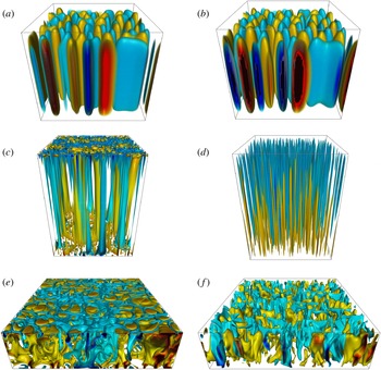
Three primary dynamical regimes of MC are found, which we refer to as the cellular, columnar and turbulent regimes. Each regime is illustrated in figure 1, where each panel shows a simulation domain with aspect ratio
 $5\unicode[STIX]{x1D706}_{c}\times 5\unicode[STIX]{x1D706}_{c}\times 1$
, where
 $\unicode[STIX]{x1D706}_{c}\approx 0.22$
,
 $0.15$
and
 $0.73$
, respectively, for the three different cases. Only the first two regimes are considered to be magnetically constrained in the sense that the Lorentz force plays a leading-order role in the dynamics. Each regime can be uniquely identified by: (1) the scaling of the heat transport and flow speeds with buoyancy forcing; (2) the physical structure and spectral characteristics of the flows; and (3) the relative sizes of each term in the governing equations.
Volumetric renderings of the three magnetoconvection regimes identified in the present study. Isosurfaces of fluctuating temperature are shown in the first column (a,c,e); isosurfaces of the vertical velocity are shown in the second column (b,d,f). (a,b) The cellular regime (
 $Q=10^{7}$
,
 $Ra=1.3\times 10^{8}$
); (c,d) the columnar regime (
 $Q=10^{8}$
,
 $Ra=4\times 10^{10}$
); (e,f) the turbulent regime (
 $Q=10^{4}$
,
 $Ra=2\times 10^{7}$
). For all three cases, the Prandtl number is fixed at
 $Pr=1$
, and an aspect ratio of
 $5\unicode[STIX]{x1D706}_{c}\times 5\unicode[STIX]{x1D706}_{c}\times 1$
is shown, where
 $\unicode[STIX]{x1D706}_{c}$
is the critical wavelength (see main text for details).

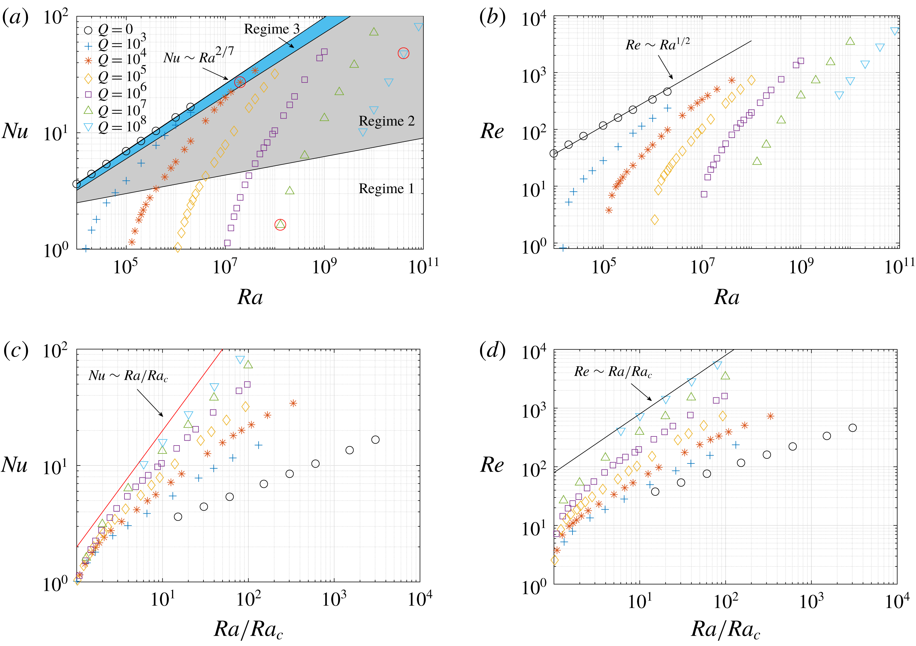
Figure 2(a,b) show the Nusselt number (
 $Nu$
) and Reynolds number (
 $Re$
) versus the Rayleigh number (
 $Ra$
) for all
 $Pr=1$
cases. The non-magnetic (
 $Q=0$
) case is shown for comparison, along with the
 $Nu\sim Ra^{2/7}$
scaling typically found in studies using moderate
 $Ra$
and
 $Pr=O(1)$
(e.g. Castaing et al.
Reference Castaing, Gunaratne, Heslot, Kadanoff, Libchaber, Thomae, Wu, Zaleski and Zanetti1989) and the ‘free-fall’ scaling,
 $Re\sim Ra^{1/2}$
. All of the MC cases show qualitatively similar behaviour to each other in their functional dependence of
 $Nu$
and
 $Re$
on
 $Ra$
. Figure 2(c,d) show
 $Nu$
and
 $Re$
versus
 $Ra/Ra_{c}$
, where the similarities between cases with different
 $Q$
values and the asymptotic behaviours can be more clearly seen.
Heat transport and flow speeds in magnetoconvection. (a) Nusselt number versus Rayleigh number (cases shown in figures 1 and 9 are marked with a red circle); (b) Reynolds number versus Rayleigh number; (c) Nusselt number versus
 $Ra/Ra_{c}$
; (d) Reynolds number versus
 $Ra/Ra_{c}$
. The three different regimes identified in the present study are illustrated in (a); regime 1 is the cellular regime, regime 2 is the columnar regime and regime 3 is the turbulent regime.

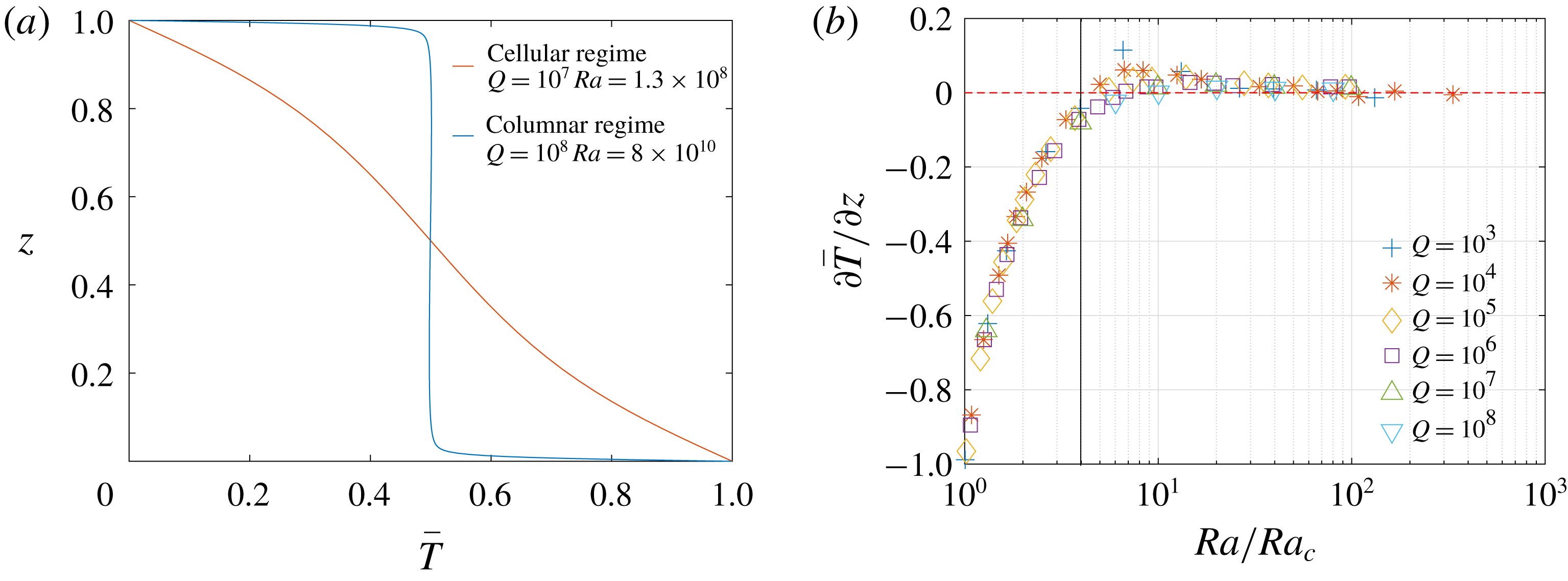
Characteristics of the time- and horizontally averaged (mean) temperature (
 $Pr=1$
). (a) Mean temperature profiles for two representative cases within the cellular and columnar regimes. (b) Vertical gradient of the mean temperature at the vertical midplane. The solid black line roughly suggests the transition from the cellular regime to the columnar regime. The dashed red line indicates an isothermal interior.

The first, cellular regime is characterized by the cellular structures reminiscent of linear convection, as illustrated in the visualizations of figure 1(a,b). In this regime, the heat transfer and flow speeds increase rapidly with increasing
 $Ra$
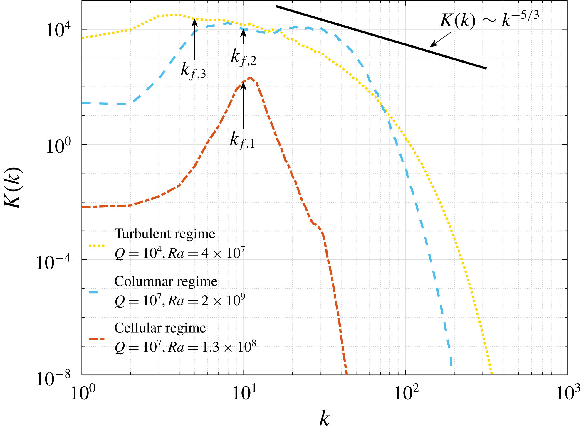
, but with a slope that continuously decreases. The time-averaged mean temperature profile for a typical case in this regime is shown in figure 3(a). Here, convective nonlinearities remain weak and the characteristic scale of fluid motion remains dominated by the critical horizontal wavenumber, as illustrated in the kinetic energy spectra shown in figure 4.
Instantaneous kinetic energy spectra,
 $K(k)$
, from representative cases of the three different magnetoconvection regimes; spectra are computed at the vertical midplane (
 $z=0$
). The cellular regime is shown with the dash-dot line (
 $Q=10^{7}$
,
 $Ra=1.3\times 10^{8}$
); the columnar regime is shown with the dashed line (
 $Q=10^{7}$
,
 $Ra=2\times 10^{9}$
); and the turbulent regime is shown with the dotted line (
 $Q=10^{4}$
,
 $Ra=4\times 10^{7}$
). The critical (forcing) wavenumbers for each case are
 $k_{f,1}$
,
 $k_{f,2}$
and
 $k_{f,3}$
. The
 $k^{-5/3}$
slope is shown for reference.

When
 $Ra$
is increased to
 $\simeq 4Ra_{c}$
, the slope of the (
 $Nu,Ra$
) and (
 $Re,Ra$
) curves for each value of
 $Q$
appear to approach a constant value over a wide range of
 $Ra$
. We refer to this (second) regime as ‘columnar’ because of the characteristic structure of the flow field shown in figure 1(c,d), which consists of a network of spatially localized columns that span the depth of the layer. Flow speeds, as indicated by the Reynolds number in figure 2(b), become large in this regime in the sense that an equivalent
 $Q=0$
case would yield a turbulent flow, yet the fluid remains quasi-laminar and coherent. The simulations show that the columnar regime occupies an increasing range of
 $Ra$
as
 $Q$
is increased. The spatial localization of the convection leads to a locally flattened kinetic energy spectrum centred near the critical wavenumber (
 $k=10$
for the case shown), as illustrated in figure 4. Within the columnar regime, figure 3(a,b) shows that the fluid interior becomes nearly isothermal and the thermal boundary layers are well-established.
Two-dimensional (
 $x,z$
) slice of temperature for a typical case in the magnetically constrained columnar regime (
 $Q=10^{6},Ra=1.5\times 10^{8},Pr=1$
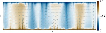
), showing the broadening of thermal structures as hot (cold) fluid ascends (descends). The arrows indicate the velocity in the plane.

As first observed by Cioni et al. (Reference Cioni, Chaumat and Sommeria2000), the interior mean temperature gradient can be positive for some of the cases. A possible explanation for this reversed (stable) gradient is due to the vertical structure of the anisotropic columns, as illustrated in the vertical slice of the temperature in figure 5. A given convection column exhibits an asymmetric structure about
 $z=0.5$
; for instance, upwelling flow tends to be thin near the bottom boundary where flow converges, and broader near the upper boundary where flow diverges. Horizontally averaging this flow structure results in a weakly stable interior temperature profile. The columns act as an efficient heat transfer mechanism in the sense that heat is carried directly from boundary to boundary with limited horizontal mixing.
The third, turbulent MC regime is marked by a decrease in the slope of both the
 $Nu$
(cf. Cioni et al.
Reference Cioni, Chaumat and Sommeria2000) and
 $Re$
scalings with
 $Ra$
. Here the columns disappear and, as a result, the flattened kinetic energy spectra observed in the columnar regime transition to a broader spectrum (figure 4) that is suggestive of a direct energy cascade and the development of an inertial subrange (the Kolmogorov spectrum
 $K(k)\sim k^{-5/3}$
is plotted for reference). However, the development of an inertial subrange is very slow and requires very large
 $Ra$
. The Lorentz force still plays an important role in the dynamics, and extremely large Rayleigh numbers are required to leave the third regime and access flows in which the Lorentz force plays a negligible role.
Comparison of simulation results with the
 $Pr=0.025$
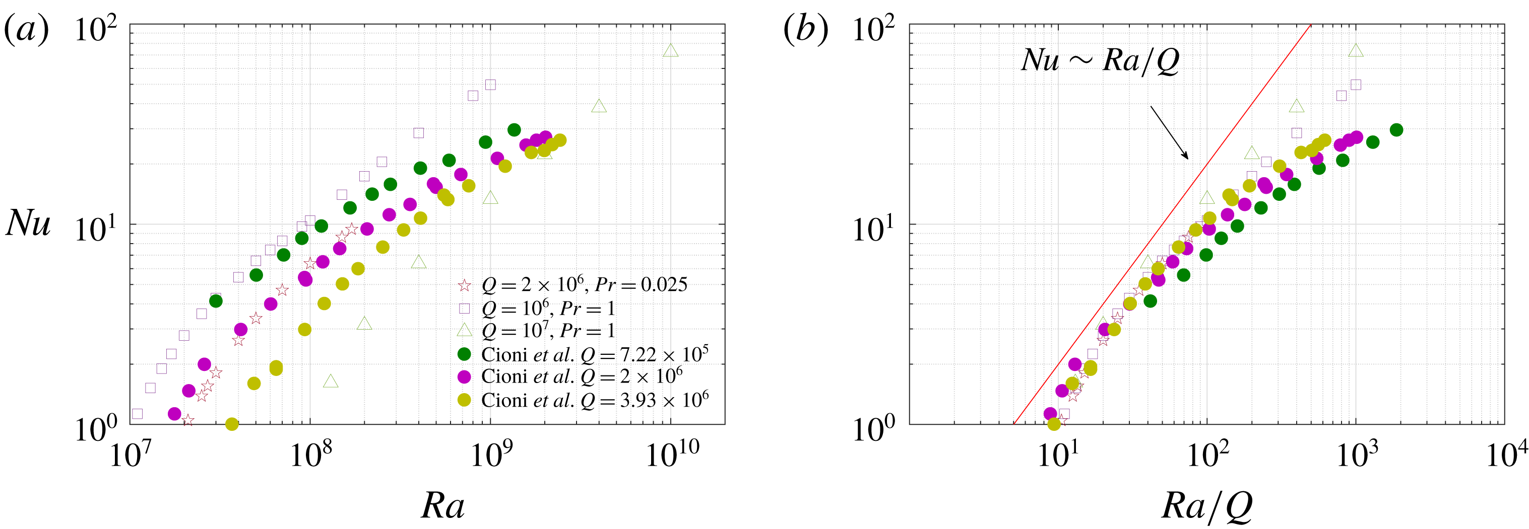
experimental data of Cioni et al. (Reference Cioni, Chaumat and Sommeria2000). (a) Nusselt number versus Rayleigh number; (b) Nusselt number versus
 $Ra/Q$
.

3.2 The influence of the Prandtl number
A total of ten simulations with
 $Pr=0.025$
have also been carried out to determine the dynamical influence of the thermal Prandtl number, and to compare with available data from laboratory experiments that use this same value of
 $Pr$
. Specifically, we use
 $Q=2\times 10^{6}$
to compare with the results of Cioni et al. (Reference Cioni, Chaumat and Sommeria2000) who used a cylindrical container filled with mercury. Figure 6 shows the Cioni et al. (Reference Cioni, Chaumat and Sommeria2000) data along with the
 $Pr=0.025$
and two
 $Pr=1$
cases with comparable
 $Q$
values (
 $10^{6}$
and
 $10^{7}$
) from the present work. In general, similar behaviour is seen between the simulations and the experimental data, despite the differences in boundary conditions and geometry. As revealed by our results, the regime I of Cioni et al. (Reference Cioni, Chaumat and Sommeria2000) actually consists of two distinct magnetically constrained regimes (cellular and columnar) in which the flow cannot accurately be described as turbulent. Although they suggest a
 $Nu\sim Ra/Q$
fit to their data, our simulations show that this fit only arises at much higher values of
 $Q$
. The most significant discrepancies between the two datasets appear at higher values of
 $Ra$
(or
 $Ra/Q$
), where the Cioni et al. (Reference Cioni, Chaumat and Sommeria2000) data shows a lower slope in comparison with the simulations (both
 $Pr=0.025$
and
 $Pr=1$
). Because this difference is largest at higher values of
 $Ra$
, it might be due to, as suggested by Cioni et al. (Reference Cioni, Chaumat and Sommeria2000), the formation of a large-scale circulation in the experimental apparatus due to the eventual loss of magnetic constraint and flow anisotropy (Vogt et al.
Reference Vogt, Horn, Grannan and Aurnou2018a
; Lim et al.
Reference Lim, Chong, Ding and Xia2019). Moreover, at the highest values of
 $Ra$
accessed by Cioni et al. (Reference Cioni, Chaumat and Sommeria2000) it is likely that the dynamics are within the third regime, within which different values of
 $Pr$
might lead to different scaling behaviour. Additional studies using the cylindrical geometry and higher values of
 $Ra$
are necessary to quantify this effect in more detail.
We find that the
 $Nu$
–
 $Ra$
scaling behaviour for
 $Pr=0.025$
is nearly identical to that observed for the
 $Pr=1$
cases, as shown in figure 6(b). In addition, we can identify the cellular and columnar regimes for the
 $Pr=0.025$
cases based on the
 $Nu$
scaling and flow structures. We note that single-mode MC dynamics are also
 $Pr$
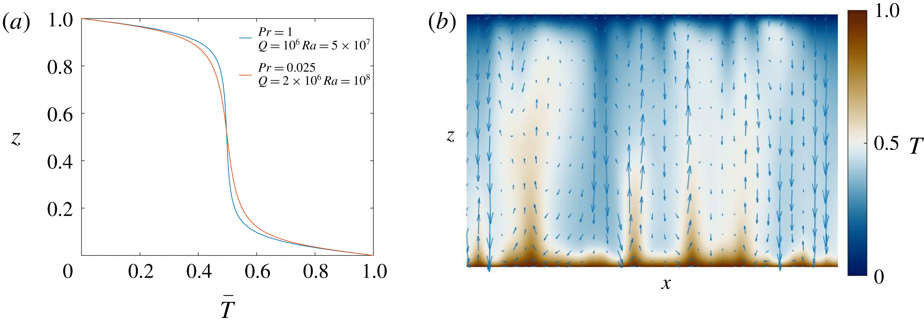
-independent (Julien, Knobloch & Tobias Reference Julien, Knobloch and Tobias1999; Matthews Reference Matthews1999). The mean temperature profiles in figure 7(a) show that the thickness of the thermal boundary layers observed in the
 $Pr=0.025$
cases is comparable to the corresponding cases with
 $Pr=1$
for a given value of
 $Ra/Q$
. However, a larger interior temperature gradient is present for the
 $Pr=0.025$
cases. Figure 7 shows a two-dimensional (
 $x,z$
) slice of the temperature field for a case in the columnar regime with
 $Pr=0.025$
. Both
 $Pr=0.025$
and
 $Pr=1$
cases show similar anisotropic columnar structures. However, as might be expected with a smaller
 $Pr$
, heat diffuses to the surrounding fluid more rapidly before it is carried to the top of the layer. As a result, cases with a smaller
 $Pr$
are expected to require a larger
 $Ra/Ra_{c}$
to reach an isothermal interior for finite values of
 $Q$
.
The influence of the thermal Prandtl number on magnetoconvection. (a) Time- and horizontally averaged (mean) temperature profile for cases with different
 $Pr$
but the same
 $Ra/Q$
; (b) two-dimensional (
 $x,z$
) slices of temperature for columnar regime with
 $Pr=0.025,(Q=2\times 10^{6},Ra=1.7\times 10^{8})$
.

3.3 Balances
The magnetic interaction parameter,
 $N={\mathcal{B}}^{2}L/(\unicode[STIX]{x1D70C}\unicode[STIX]{x1D707}\unicode[STIX]{x1D702}U)$
(where
 $L$
and
 $U=|\boldsymbol{u}|$
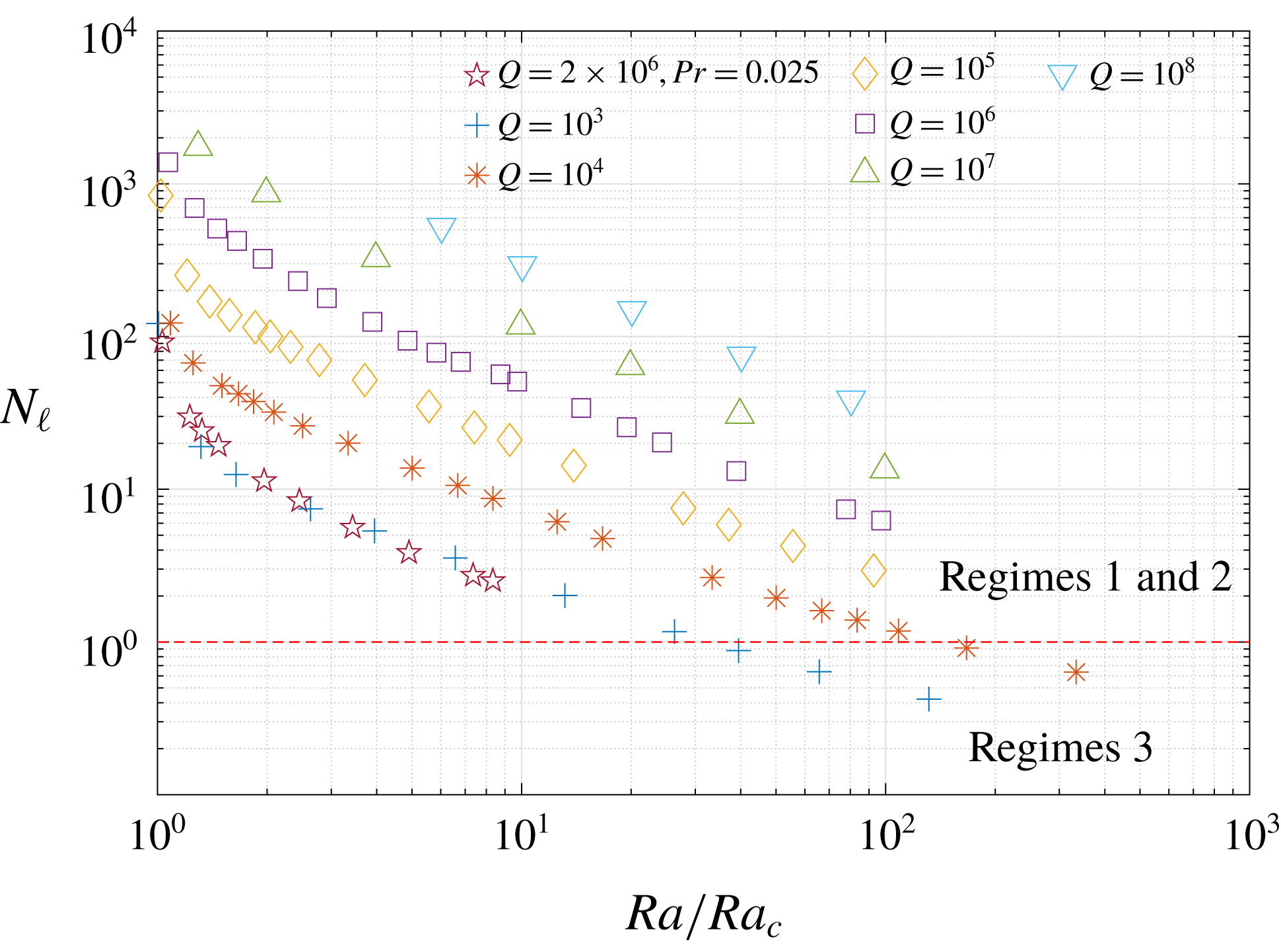
are generic characteristic length and speed scales) can be used to estimate the relative magnitudes of the Lorentz force to the advection terms in the momentum equation (e.g. Davidson Reference Davidson2013). If one assumes that
 $L\equiv H$
, we have
 $N=Q/Re$
(e.g. Cioni et al.
Reference Cioni, Chaumat and Sommeria2000). In the present work, however, a definition that better captures the transition between the regimes identified above can be found by incorporating the
 $Q$
-dependent horizontal length scale of the convective flows into the definition of the interaction parameter; we denote this rescaled interaction parameter by
 $N_{\ell }$
. From the vertical component of the momentum equation, for instance, we have
 $$\begin{eqnarray}N_{\ell }\sim \frac{Lorentz~force}{advection}\sim \frac{|Q\unicode[STIX]{x2202}_{z}b_{z}|}{|u_{z}\unicode[STIX]{x2202}_{z}u_{z}|}\sim Q\frac{|b_{z}|}{|u_{z}|^{2}}\sim Q\frac{|\ell ^{2}|}{|u_{z}|}\sim \frac{Q^{2/3}}{Re},\end{eqnarray}$$
where, from the vertical component of the induction equation, we have used
 $$\begin{eqnarray}b_{z}=-\unicode[STIX]{x1D6FB}^{-2}\unicode[STIX]{x2202}_{z}u_{z}\Rightarrow |b_{z}|\sim \ell ^{2}|u_{z}|=\ell ^{2}Re.\end{eqnarray}$$
We assume
 $\ell \sim Q^{-1/6}$
, vertical derivatives are of order one, and the vertical component of the velocity is asymptotically larger than the horizontal components so that
 $u_{z}\sim Re$
(e.g. Matthews Reference Matthews1999). An identical relationship can be found from the horizontal components of the momentum equation by relating the horizontal and vertical velocity components through the continuity equation. Thus, the transition from the columnar regime to the turbulent regime is expected when
 $N_{\ell }\simeq 1$
. Figure 8 shows the interaction parameter
 $N_{\ell }$
plotted versus
 $Ra/Ra_{c}$
. The dashed red line indicates the boundary between the columnar and turbulent regimes. It is suggested that with a larger
 $Q$
value, a larger
 $Ra/Ra_{c}$
is required to leave the columnar regime. The
 $Pr=0.025$
data suggests that smaller values of
 $Pr$
will yield a narrower (in terms of
 $Ra$
) columnar regime, and a broader turbulent regime for a fixed value of
 $Q$
.
Rescaled interaction parameter
 $N_{\ell }=Q^{2/3}/Re$
versus
 $Ra/Ra_{c}$
. The Lorentz force remains dominant provided
 $N_{\ell }\gtrsim 1$
. The dashed red line shows the approximate location for the transition from the columnar regime to the turbulent regime. Unless explicitly stated all curves are for
 $Pr=1$
.

Instantaneous dynamical balances in
 $Pr=1$
magnetoconvection. Vertical profiles of the horizontal root mean square of each term present in the momentum equation (2.1) (a,b,d,e,g,h) and fluctuating heat equation (2.3) (c,f,i) are shown. The cellular regime (
 $Q=10^{7}$
,
 $Ra=1.3\times 10^{8}$
): (a) horizontal forces
 $F_{xy}=(F_{x}^{2}+F_{y}^{2})^{1/2}$
; (b) vertical forces
 $F_{z}$
; (c) all terms in the fluctuating heat equation. The columnar regime (
 $Q=10^{8}$
,
 $Ra=4\times 10^{10}$
): (d) horizontal forces
 $F_{xy}$
; (e) vertical forces
 $F_{z}$
; (f) all terms in the fluctuating heat equation. The turbulent regime (
 $Q=10^{4}$
,
 $Ra=2\times 10^{7}$
): (g) horizontal forces; (h) vertical forces; (i) all terms in the fluctuating heat equation. Vertical velocity, horizontal velocity and horizontal gradient are given by
 $u_{z}$
,
 $u_{h}=(u_{x}^{2}+u_{y}^{2})^{1/2}$
and
 $\unicode[STIX]{x1D735}_{h}=(\unicode[STIX]{x2202}_{x},\unicode[STIX]{x2202}_{y},0)$
. Advection and the Lorentz, viscous, buoyancy and pressure gradient forces are denoted by
 $F_{a}$
,
 $F_{l}$
,
 $F_{v}$
,
 $F_{b}$
and
 $F_{p}$
, respectively. Inertia in the horizontal and vertical components of the momentum equation are denoted by
 $\unicode[STIX]{x2202}_{t}u_{h}$
and
 $\unicode[STIX]{x2202}_{t}u_{z}$
, respectively.

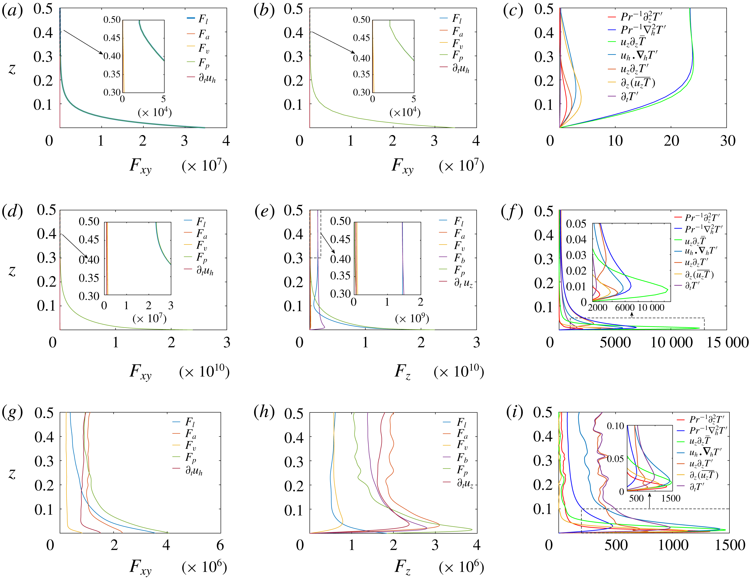
Figure 9 shows vertical profiles of the instantaneous horizontal root mean square of each term in the governing equations, for representative
 $Pr=1$
cases in the cellular (a–c), columnar (d–f) and turbulent (g–i) regimes. Instantaneous values of the profiles are used to demonstrate that the force balances in the magnetically constrained regimes apply at all times, and show remarkably smooth profiles; therefore, the choice of the particular instant in time does not affect the results. The interior and boundary layer are characterized by distinct balances, so it is helpful to consider the two regions separately. As predicted from the linear asymptotic scalings (e.g. Chandrasekhar Reference Chandrasekhar1961; Matthews Reference Matthews1999), figure 9(a,b,d,e) show that, for the cellular and columnar regimes, the leading-order force balance within the interior is between the Lorentz force (
 $F_{l}$
), buoyancy force (
 $F_{b}$
) and horizontal pressure gradient (
 $F_{p}$
),
 $$\begin{eqnarray}0\approx Q\unicode[STIX]{x2202}_{z}b_{z}+\frac{Ra}{Pr}T^{\prime },\quad 0\approx Q\unicode[STIX]{x2202}_{z}b_{h}-\unicode[STIX]{x1D735}_{\bot }\unicode[STIX]{x1D6F1}\quad (\text{Regimes 1 and 2, interior}).\end{eqnarray}$$
In the boundary layers we find that the pressure gradient balances the Lorentz force,
 $$\begin{eqnarray}0\approx Q\unicode[STIX]{x2202}_{z}\boldsymbol{b}-\unicode[STIX]{x1D735}\unicode[STIX]{x1D6F1},\quad (\text{Regimes 1 and 2, boundary layers}).\end{eqnarray}$$
For the cellular regime, the vertical advection of the mean temperature and the horizontal diffusion terms are in dominant balance in the entire flow domain (cf. Matthews Reference Matthews1999),
 $$\begin{eqnarray}u_{z}\unicode[STIX]{x2202}_{z}\overline{T}\approx Pr^{-1}\unicode[STIX]{x1D6FB}_{\bot }^{2}T^{\prime },\quad \text{(Regime 1)}.\end{eqnarray}$$
For the columnar regime, in the interior, the dominant terms in the fluctuating heat equation (2.3) are
 $$\begin{eqnarray}\unicode[STIX]{x2202}_{t}T^{\prime }+u_{z}\unicode[STIX]{x2202}_{z}T^{\prime }\approx Pr^{-1}\unicode[STIX]{x1D6FB}_{\bot }^{2}T^{\prime },\quad \text{(Regime 2, interior)}.\end{eqnarray}$$
whereas vertical advection of the mean temperature dominates in the boundary layers. The balance in the interior suggests that for a fixed value of
 $Q$
, the horizontal length scale of the columns is, in addition to being strongly dependent upon
 $Q$
, also limited by horizontal thermal diffusion.
In the turbulent regime (figure 9 d–f), the simulations show that advection, inertia and the pressure gradient and buoyancy forces are important throughout the fluid layer. The turbulent regime possesses no instantaneous force balance in the sense that inertia and advection are dominant, whereas the Lorentz and viscous forces are subdominant. The heat equation is dominated by nonlinear advection within the interior, and all terms except horizontal diffusion play a significant role in the thermal boundary layer.
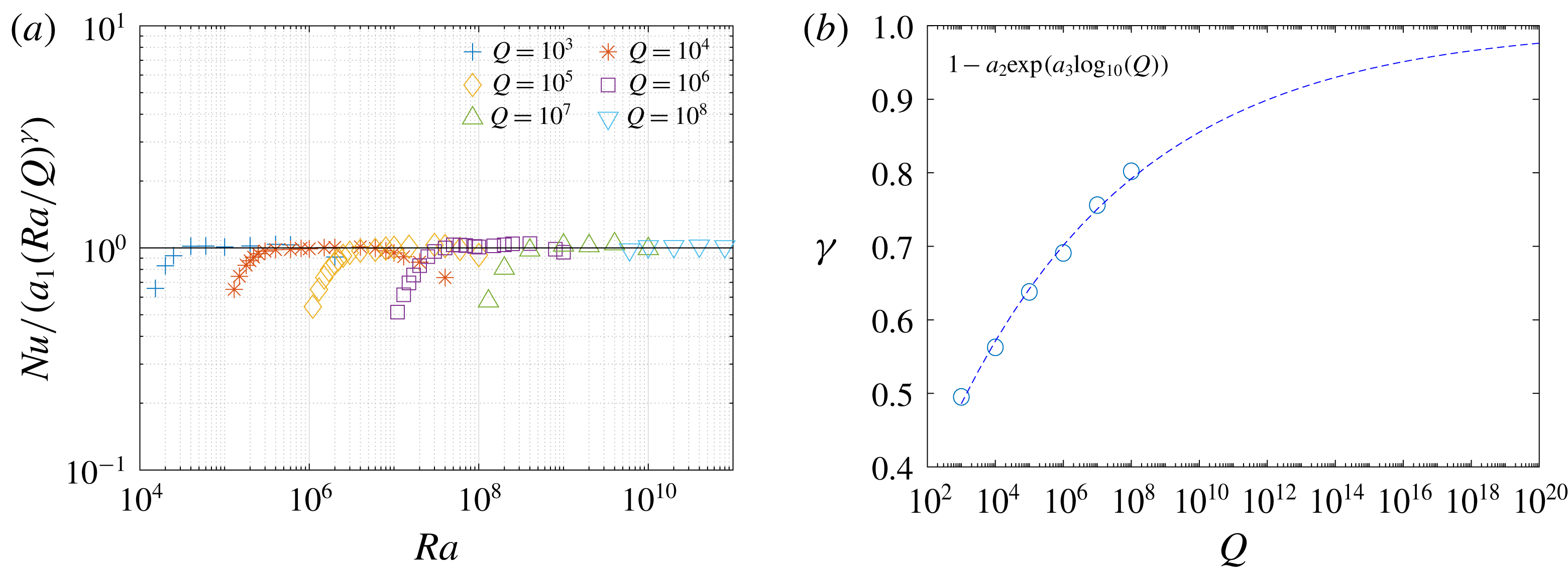
Power-law fits to the heat transport scaling within the columnar regime for
 $Pr=1$
. (a) The compensated Nusselt number,
 $Nu/(a_{1}(Ra/Q)^{\unicode[STIX]{x1D6FE}})$
, versus the Rayleigh number,
 $Ra$
, where
 $\unicode[STIX]{x1D6FE}=1-a_{2}\exp (a_{3}\log _{10}(Q))$
. (b)
 $\unicode[STIX]{x1D6FE}$
plotted versus
 $Q$
. Here
 $a_{1}=0.4088$
,
 $a_{2}=0.8847$
, and
 $a_{3}=-0.1810$
.

3.4 Power-law fits
The
 $Pr=1$
heat transport data shown in figure 2(c) suggests that a power-law scaling of the form
 $Nu=a_{1}(Ra/Q)^{\unicode[STIX]{x1D6FE}}$
(where
 $a_{1}$
is a constant) is present in the second, columnar regime, where
 $\unicode[STIX]{x1D6FE}$
appears to approach unity for increasing
 $Q$
. Since
 $\unicode[STIX]{x1D6FE}$
increases with
 $Q$
at a decreasing rate, we first compute
 $\unicode[STIX]{x1D6FE}$
in the columnar regime for individual
 $Q$
values, then compute a least-squares fit of the form
 $\unicode[STIX]{x1D6FE}=1-a_{2}\exp (a_{3}\log _{10}(Q))$
, where
 $a_{2}$
and
 $a_{3}$
are constants. This latter exponential fit for
 $\unicode[STIX]{x1D6FE}$
has no physical basis and is meant only to provide a guide for the behaviour at large values of
 $Q$
. Figure 10(a) shows the rescaled, or compensated, Nusselt number,
 $Nu/(a_{1}(Ra/Q)^{\unicode[STIX]{x1D6FE}})$
, plotted versus the Rayleigh number,
 $Ra$
, with the fitting results:
 $a_{1}=0.4088$
,
 $a_{2}=0.8847$
,
 $a_{3}=-0.1810$
.
Figure 10(b) shows in detail how
 $\unicode[STIX]{x1D6FE}$
changes with
 $Q$
. The exponential fit suggests that
 $\unicode[STIX]{x1D6FE}$
reaches
 $0.95$
around
 $Q=10^{16}$
, which is close to estimates for
 $Q$
in the Earth’s outer core (e.g. Gillet et al.
Reference Gillet, Jault, Canet and Fournier2010).
The flow speeds in the columnar regime can be understood by balancing the Lorentz force
 $F_{l}$
and buoyancy force
 $F_{b}$
in the vertical component of the momentum equation, such that
 $$\begin{eqnarray}Q\unicode[STIX]{x2202}_{z}b_{z}\approx (Ra/Pr)T^{\prime }\Rightarrow Qb_{z}\sim (Ra/Pr)T^{\prime },\end{eqnarray}$$
where we again assume
 $\ell \sim Q^{-1/6}$
, vertical derivatives are order one,
 $u_{z}\sim Re$
and
 $|b_{z}|\sim \ell ^{2}Re$
. If we also assume a weak
 $Q$
-dependence of
 $T^{\prime }$
we then have
 $$\begin{eqnarray}Q\ell ^{2}Re\sim Ra/Pr\Rightarrow Re\sim Ra/(PrQ^{2/3}).\end{eqnarray}$$
We emphasize that this magnetically constrained scaling is steeper than the turbulent, free-fall scaling in which
 $Re\sim Ra^{1/2}$
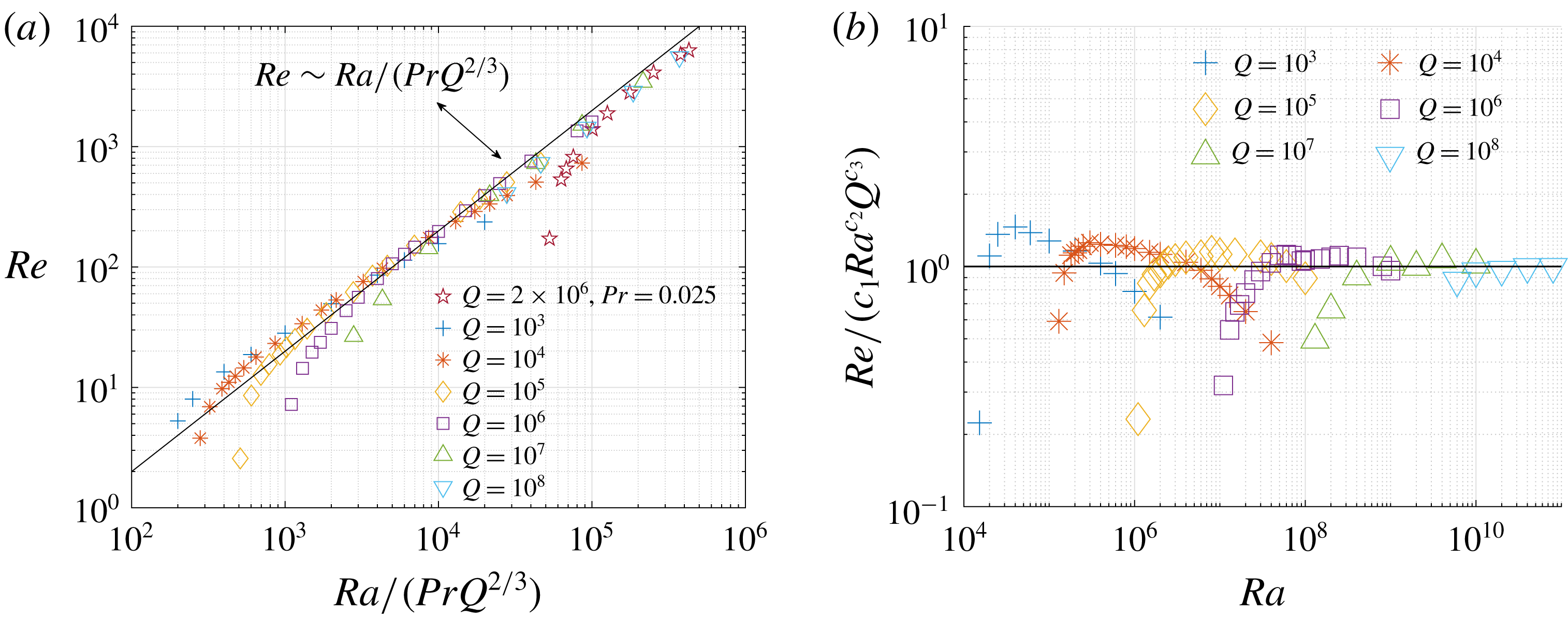
due to the linearity of the balance. In figure 11(a) we show that this scaling collapses the data well in the columnar regime. A least-squares fitting of
 $Re=c_{1}Ra^{c_{2}}Q^{c_{3}}$
applied to the
 $Re$
data in the columnar regime gives
 $c_{1}=0.0324$
,
 $c_{2}=0.9542$
, and
 $c_{3}=-0.6461$
. Figure 11(b) shows the compensated Reynolds number,
 $c_{1}^{-1}ReRa^{-c_{2}}Q^{-c_{3}}$
, plotted versus
 $Ra$
. As might be expected if one assumes an asymptotic state exists, the coefficients fit the data better as
 $Q$
increases.
Power-law scaling for the Reynolds number. (a) The Reynolds number versus
 $Ra/(PrQ^{2/3})$
. (b) The compensated Reynolds number,
 $Re/(c_{1}Ra^{c_{2}}Q^{c_{3}})$
, plotted versus the Rayleigh number,
 $Ra$
. Here
 $c_{1}=0.0324$
,
 $c_{2}=0.9542$
,
 $c_{3}=-0.6461$
are given by a least-squares fitting of
 $Re=c_{1}Ra^{c_{2}}Q^{c_{3}}$
applied to the
 $Re$
data in the columnar regime.

4 Conclusions
A systematic parameter survey of quasi-static magnetoconvection was carried out in a plane layer geometry. The results show three primary magnetoconvection regimes, with each regime distinguishable through unique heat transfer and convective-speed scalings, flow morphology, spectral characteristics and dominant balances in the momentum and heat equations. For a fixed value of
 $Q$
, and in order of increasing Rayleigh number, the first two regimes are characterized by a predominant Lorentz force and are therefore magnetically constrained; the third regime is transitional and weakly influenced by the Lorentz force. For large values of
 $Q$
, the convective flow is highly anisotropic in both the first (cellular) and second (columnar) regimes. The columnar regime is characterized by spatially localized convective columns that span the fluid depth, and numerical analysis of the governing equations demonstrates that this regime is characterized by asymptotically small advection and inertia, despite large Reynolds numbers.
Heat transport in the columnar regime is controlled by the thermal boundary layers and shows a power-law scaling with the Rayleigh number. Previous MC studies have suggested a
 $Nu\sim (Ra/Q)$
scaling for the
 $Q\rightarrow \infty$
limit. More generally, our simulations suggest a scaling of the form
 $Nu\sim (Ra/Q)^{\unicode[STIX]{x1D6FE}}$
, with
 $\unicode[STIX]{x1D6FE}\rightarrow 1$
as
 $Q\rightarrow \infty$
. Thus, previous work finding
 $\unicode[STIX]{x1D6FE}=1/2$
(Aurnou & Olson Reference Aurnou and Olson2001; Yu et al.
Reference Yu, Zhang and Ni2018) and
 $\unicode[STIX]{x1D6FE}=2/3$
(Burr & Müller Reference Burr and Müller2001) are transitional and observable only at relatively small values of
 $Q$
.
For non-magnetic convection, the so-called ‘ultimate’ regime is a hypothetical state of convection in which the entire fluid layer is turbulent, and is thought to arise in the asymptotic limit of large
 $Ra$
(Kraichnan Reference Kraichnan1962). Simulations of unconstrained convection in triply periodic domains have shown that the ultimate regime may occur in the absence of thermal boundary layers (Lohse & Toschi Reference Lohse and Toschi2003), and recent strongly forced, two-dimensional simulations in a bounded domain also show a transition in heat transport that is indicative of an ultimate regime (Zhu et al.
Reference Zhu, Mathai, Stevens, Verzicco and Lohse2018). Laboratory experiments using internal heating also show evidence of reaching an ultimate regime (Lepot, Aumaître & Gallet Reference Lepot, Aumaître and Gallet2018). When additional forces are present that constrain the convection, regimes of flow that are fundamentally different from those in unconstrained convection can be realized. Our results suggest that the columnar regime represents an ultimate state for magnetically constrained, quasi-static MC. Of course, the relatively limited accessible values of
 $Q$
(and
 $Ra$
) might hinder the ability to observe the
 $Nu\sim Ra/Q$
scaling that is thought to be indicative of this MC state, though our data suggests a trend toward this limit.
Finally, the Coriolis force, like the Lorentz force, can also act as a ‘constraint’ on convection that results in anisotropic flows. In contrast to MC, however, rotationally constrained convection does exhibit a turbulent state, as observed with direct numerical simulation (e.g. Favier, Silvers & Proctor Reference Favier, Silvers and Proctor2014; Guervilly, Hughes & Jones Reference Guervilly, Hughes and Jones2014; Stellmach et al.
Reference Stellmach, Lischper, Julien, Vasil, Cheng, Ribeiro, King and Aurnou2014) and numerical simulation of an asymptotically reduced equation set (Julien et al.
Reference Julien, Rubio, Grooms and Knobloch2012; Rubio et al.
Reference Rubio, Julien, Knobloch and Weiss2014). This difference may be due to the different energetic contributions that each of these two forces makes to convection, and to the different asymptotic scalings that characterize the two types of convection. While the Coriolis force has zero direct contribution to the energetics of rotating convection, the quasi-static Lorentz force is purely dissipative. Moreover, all three components of the velocity vector are of comparable magnitude in rotationally constrained convection (Sprague et al.
Reference Sprague, Julien, Knobloch and Werne2006), yet in MC the vertical component of the velocity vector is asymptotically larger than the corresponding horizontal components that results in different asymptotic-ordering of the various forces in the momentum equation (Matthews Reference Matthews1999). In particular, in large-
 $Q$
MC, the viscous force is asymptotically larger than the inertial force, whereas these two terms are of the same asymptotic order in rotationally constrained convection. Understanding how the Lorentz and Coriolis forces act in combination on convection is important in understanding magnetic field generation in stars and planets. Although numerical simulations have led to significant advances in our understanding of the role played by these two forces in convection (e.g. Yadav, Gastine & Christensen Reference Yadav, Gastine and Christensen2016; Aubert, Gastine & Fournier Reference Aubert, Gastine and Fournier2017; Schaeffer et al.
Reference Schaeffer, Jault, Nataf and Fournier2017), it is currently unknown what ultimate state appears at high Rayleigh numbers, or if such a state exists at all.
Acknowledgements
The authors thank two anonymous referees, whose comments helped to improve this manuscript significantly. This work was supported by the National Science Foundation under grant EAR #1620649 (M.Y., M.A.C., S.M. and K.J.). S.M.T. was supported by funding from the European Research Council (ERC) under the European Union’s Horizon 2020 research and innovation program (agreement no. D5S-DLV-786780). This work utilized the RMACC Summit supercomputer, which is supported by the National Science Foundation (awards ACI-1532235 and ACI-1532236), the University of Colorado Boulder and Colorado State University. The Summit supercomputer is a joint effort of the University of Colorado Boulder and Colorado State University. The authors acknowledge the Texas Advanced Computing Center (TACC) at The University of Texas at Austin for providing high-performance computing resources that have contributed to the research results reported within this paper. Volumetric rendering was performed with the visualization software VAPOR (Clyne & Rast Reference Clyne and Rast2005; Clyne et al. Reference Clyne, Mininni, Norton and Rast2007).
Appendix
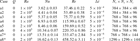
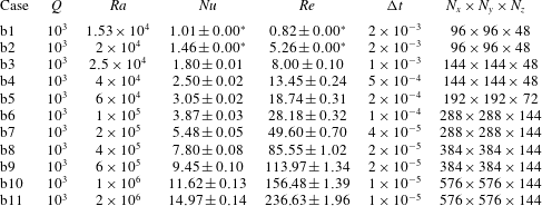
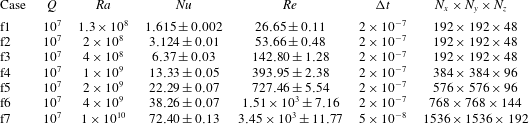
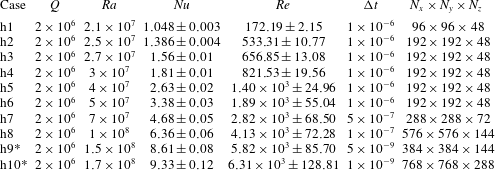
Here we provide tables with details of the numerical simulations.
Details of the RBC cases. The time step size is
 $\unicode[STIX]{x0394}t$
. The spatial resolution is denoted by
 $N_{x}\times N_{y}\times N_{z}$
. The box ratio is
 $10\unicode[STIX]{x1D706}_{c}\times 10\unicode[STIX]{x1D706}_{c}\times 1$
in cases without *, and
 $5\unicode[STIX]{x1D706}_{c}\times 5\unicode[STIX]{x1D706}_{c}\times 1$
in cases with * above. The horizontal wavenumber
 $k_{c}=2.2215$
.

Details of the
 $Q=10^{3}$
cases. The time step size is
 $\unicode[STIX]{x0394}t$
. The spatial resolution is denoted by
 $N_{x}\times N_{y}\times N_{z}$
. The box ratio is
 $10\unicode[STIX]{x1D706}_{c}\times 10\unicode[STIX]{x1D706}_{c}\times 1$
. The horizontal wavenumber
 $k_{c}=5.6842$
. The case with
 $\pm 0.00^{\ast }$
indicates that it is just above critical Rayleigh and has a stable
 $Nu$
or
 $Re$
.

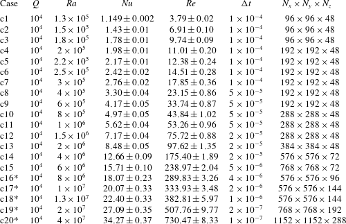
Details of the
 $Q=10^{4}$
cases. The time step size is
 $\unicode[STIX]{x0394}t$
. The spatial resolution is denoted by
 $N_{x}\times N_{y}\times N_{z}$
. The box ratio is
 $10\unicode[STIX]{x1D706}_{c}\times 10\unicode[STIX]{x1D706}_{c}\times 1$
in cases without *, and
 $5\unicode[STIX]{x1D706}_{c}\times 5\unicode[STIX]{x1D706}_{c}\times 1$
in cases with * above. The horizontal wavenumber
 $k_{c}=8.6062$
.

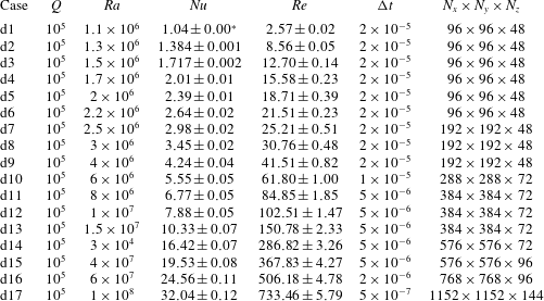
Details of the
 $Q=10^{5}$
cases. The time step is
 $\unicode[STIX]{x0394}t$
. The spatial resolution is denoted by
 $N_{x}\times N_{y}\times N_{z}$
. The box ratio is
 $10\unicode[STIX]{x1D706}_{c}\times 10\unicode[STIX]{x1D706}_{c}\times 1$
. The horizontal wavenumber
 $k_{c}=12.8343$
. The case with
 $\pm 0.00^{\ast }$
indicates that it is just above critical Rayleigh and has a stable
 $Nu$
or
 $Re$
.

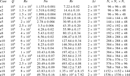
Details of the
 $Q=10^{6}$
cases. The time step is
 $\unicode[STIX]{x0394}t$
. The spatial resolution is denoted by
 $N_{x}\times N_{y}\times N_{z}$
. The box ratio is
 $10\unicode[STIX]{x1D706}_{c}\times 10\unicode[STIX]{x1D706}_{c}\times 1$
. The horizontal wavenumber
 $k_{c}=18.9823$
.

Details of the
 $Q=10^{7}$
cases. The time step is
 $\unicode[STIX]{x0394}t$
. The spatial resolution is denoted by
 $N_{x}\times N_{y}\times N_{z}$
. The box ratio is
 $10\unicode[STIX]{x1D706}_{c}\times 10\unicode[STIX]{x1D706}_{c}\times 1$
. The horizontal wavenumber
 $k_{c}=27.9622$
.

Details of the
 $Q=10^{8}$
cases. The time step is
 $\unicode[STIX]{x0394}t$
. The spatial resolution is denoted by
 $N_{x}\times N_{y}\times N_{z}$
. The box ratio is
 $5\unicode[STIX]{x1D706}_{c}\times 5\unicode[STIX]{x1D706}_{c}\times 1$
. The horizontal wavenumber
 $k_{c}=41.1115$
.

Details of the
 $Pr=0.025,Q=2\times 10^{6}$
cases. The time step is
 $\unicode[STIX]{x0394}t$
. The spatial resolution is denoted by
 $N_{x}\times N_{y}\times N_{z}$
. The box ratio is
 $10\unicode[STIX]{x1D706}_{c}\times 10\unicode[STIX]{x1D706}_{c}\times 1$
in cases without *, and
 $5\unicode[STIX]{x1D706}_{c}\times 5\unicode[STIX]{x1D706}_{c}\times 1$
in cases with * above. The horizontal wavenumber
 $k_{c}=18.9823$
.