I. INTRODUCTION
Hydrogen gas (H2) fuel is a clean energy, which is a good energy source for social sustainable development. Reference Morales-Guio, Stern and Hu1 Among many methods to obtain H2 in a large scale, water splitting with applied potential is regarded as the most promising strategy. Reference Zeng and Li2,Reference Lukowski, Daniel, English, Meng, Forticaux, Hamers and Jin3 In general, H2 could be obtained with certain potential according the half reactions of 2H+ + 2e− → H2 (the hydrogen evolution reaction, HER). Platinum (Pt) is most effective catalyst for water splitting, but the expensive price limits its wide application. Reference Zou, Huang, Goswami, Silva, Sathe, Mikmeková and Asefa4–Reference Zhou, Zhou, Zhou, Lu, Zhou, Yang, Tang, Li and Chen6 Thus, commercial electrocatalysts typically are inexpensive but inferior-performance materials, for example, nickel metal and its alloys. Reference Fan, Peng, Ye, Zhou and Guo7,Reference Deng, Ren, Deng, Yu, Yang and Bao8 To obtain electrocatalysts with low-cost and high catalytic efficiency, many researchers have focused on the transition metal-based materials because they possess the similar electronic structure with Pt. Among these alternatives, iron-based nitride, sulfide, and phosphide materials possess good catalytic properties and lower prices. So, they have been identified as promising materials for catalyzing the HER. Reference Faber, Lukowski, Qi, Kaiser and Song9–Reference Lv, Peng, Zhao, Huang and Zhang12 Furthermore, iron nitride is regarded as the most promised candidate because of it’s facile preparation and excellent chemical stability. Reference Yu, Wang, Sun, Zhao, Tian, Zhao, Liu, Wang and Fu13
There also have some works about the catalytic activities of iron nitride-based materials with different structure and composition. Reference Zhang, Xiao, Xie, Liang, Chen and Tang14–Reference Jiang, Li, Lu, Sun and Duan16 It is observed that the catalytic efficiency is mainly related to the chemical composition, structure, and material conductivity of catalysts. The nanostructure exhibited better catalytic performance than bulk because the more catalytic active sites had been exposed. Usually, the iron nitride materials are prepared with the pyrolysis of iron-based precursors, oxide sinteration, and chemical vapor deposition (CVD). But the Fe2N nanocatalysts obtained with these conventional synthetic methods often possess low crystallinity and bad dispersity in size, and, the intrinsic bad conductivity limit its catalytic performance. Reference Wang, Yin, Zhao, Tian, Yu, Wang and Fu17,Reference Agemi, Kayama, Noborisaka, Tachimoto, Shirakura and Suzuki18 So, during or after their preparation, iron nitride has to be attached onto conductive supports to improve the composite conductivity and size dispersity for higher catalytic activities. For example, Fe2N/nanocarbon composite has been prepared, and it possesses better electrocatalytic activity and chemical stability than naked Fe2N nanomaterials. Reference Schwarz, Wosylus, Wessel, Dronskowski, Hanfland, Rau and Niewa19 Nitrogen-doped reduced graphite oxide (NrGO) is a good two dimensional conductivity material, which could result in the well dispersion of Fe2N nanoparticles on the surface of NrGO. So, it may be a good choice to prepare Fe2N nanoparticles/NrGO composite to improve the HER performance.
In this work, Fe2N nanoparticles have been successfully dispersed on the surface of NrGO by a facile sol–gel method and further NH3 treatment. In this route, Fe(OH)3 sol/graphite oxide (GO) was first prepared, which granted the perfect dispersion of Fe(OH)3 on the GO surface. Then, during the following heat treatment, the precursor mixtures could be easily converted into the desired monodispersed iron nitride nanoparticles without nanoparticle aggregation. Furthermore, GO could be spontaneously be converted into NrGO, which possessed better conductivity for fast electron transfer. In result, the Fe2N/NrGO composite possessed two merits, that is, the more catalytic active site in Fe2N nanoparticles, and fast electron transfer in NrGO. The ratio of Fe2N and NrGO could be controlled by the amount of iron source and GO. With the modest ratio, the composite exhibited brilliant catalytic activity and durability in acidic media. It possesses the overpotential of 94 mV to obtain the current density of 10 mA/cm2, and its activity could be maintained for at least 10 h. That results could be compared with many other nitride catalysts in recently reports. This work may pave a new road for the preparation of monodispersed cheap iron-based nitride/NrGO composite for highly efficient HER.
II. EXPERIMENTAL SECTION
A. Chemicals
The ethanol, ammonia, FeCl3, and H2SO4 were bought from Tianjin Kermel Chemical Reagent Company (Tianjin, China), N-methyl-2-pyrrolidone and polyvinylidene fluoride were purchased from Aladdin Company (Shanghai, China), and the carbon paper was purchased from Shanghai Hesen Company (Shanghai, China).
B. The preparation of Fe2N/NrGO
Graphite oxide (GO) and Fe(OH)3 sol were firstly prepared, respectively. GO was prepared by a modified Hummers method. Reference Hummers and Offeman20 For the preparation of Fe(OH)3 sol, 2 M of FeCl3 solution was dropped into 400 mL of boiling distilled water. Then, the Fe(OH)3 sol was prepared after the solution was kept boiling for 5 min. For the synthesis of Fe2N/NrGO, 1 g of GO was firstly dispersed in 500 mL of distilled water by sonication. Then 1 mL of Fe(OH)3 sol and 5 mL of 37% ammonia were dropped into above solution, followed by stirring for 90 min. A solid was obtained after the solution was dried in an oven overnight. At last, Fe2N/NrGO composite was prepared after the solid was calcined at 800 °C for 3 h under NH3 atmosphere. The obtained sample is labeled Fe2N/NrGO. For the investigation of the best HER catalytic performance of Fe2N/NrGO composite, Fe2N/NrGO composite with different Fe2N content were also obtained by adding different amount of precursor Fe(OH)3 sol of 0.5 mol or 1.5 mol to precursor GO solution of 1 g. The obtained samples are named Fe2N/NrGO* and Fe2N/NrGO**, respectively.
C. Physical characterizations
A Bruker D8 diffractometer (Bruker corporation, Karlsruhe, Germany) using Cu Kα (λ = 1.5406 Å) radiation was used to measure the X-ray diffraction (XRD) patterns of samples. A Jobin Yvon HR 800 micro-Raman spectrometer (Horiba Jobin Yvon, Paris, France) at 457.9 nm was used to measure the Raman spectra. A VG ESCALAB MK II (VG Instruments, London, United Kingdom) with an Mg Kα (1253.6 eV) achromatic X-ray source was performed to analyze the X-ray photoelectron spectroscopy (XPS). Scanning electron microscopy (SEM) with an acceleration voltage of 5 kV and transmission electron microscopy (TEM) with an acceleration voltage of 200 kV were used to character the morphology and structure of samples.
D. Electrochemical measurements
An electrochemical station (BAS100B, CH Instruments, Shanghai, China) was used for the electrochemical measurements in a three-electrode system with a saturated calomel electrode (SCE) as the reference electrode, a carbon rod electrode as the counter electrode, and carbon paper coated with Fe2N/NrGO catalyst as the working electrode. The Fe2N/NrGO electrode was fabricated as follows: Fe2N/NrGO was firstly dispersed in N-methyl-2-pyrrolidone solvent with 5 wt% polyvinylidene fluoride under sonication and stirring to get a slurry, in which the weight ratio of Fe2N/NrGO to polyvinylidene fluoride was 8:1. Then the slurry was coated onto the surface of a carbon paper. The effective loading area was about 1 cm−2 and the loading density of Fe2N/NrGO nanocatalyst was 3 mg/cm2, which is calculated by weighing the difference of the carbon paper before and after coating. Linear sweep voltammetry was carried out in 0.5 M H2SO4 solution (deaerated by N2 gas) with a scanning rate of 5 mV/s. Based on the electrochemical impedance spectra, all the data have been corrected for a small ohmic drop. All the potentials have been calibrated to a reversible hydrogen electrode (RHE).
III. RESULTS AND DISCUSSION
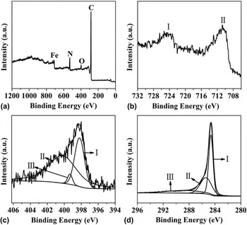
The synthesis process included the preparation of Fe(OH)3 sol/GO and the following reaction with ammonia to obtain Fe2N/NrGO composite. In this two-step process, Fe2N/NrGO composite with different Fe2N weight contents have been obtained by controlling the addition amount of Fe(OH)3 colloids into GO, and then the composites are calcined at 800 °C under ammonia atmosphere. XPS measurements can accurately test the element valence state so it is used to further explore the composition of products. As shown in Figs. 1(a) and 1(c), Fe, O, and N elements exist in the obtained composite. It can be found in Fig. 1(b) that there are two binding energy peaks at 710.5 eV and 724.1 eV, which corresponded to the Fe 2p 3/2 and 2p 1/2 level, respectively. The N 1s binding energy spectrum is displayed in Fig. 1(c), which could be fitted into three peaks. Peak I at 398.2 eV is attributed to metal nitride, which existed in Fe2N. Moreover, peak II at 399.3 eV and peak III at 400.0 eV can be ascribed to pyridinic-N and pyrrolic-N, respectively, which existed in NrGO. The XPS results indicate that the N atoms combine with C atoms in NrGO. Reference Qu, Liu, Baek and Dai21–Reference Lin, Waller, Liu, Liu and Wong24 The high-resolution C 1s XPS spectra is shown in Fig. 1(d). Binding energy peak I at 284.6 eV is ascribed to C–C bonding energy for the defect-free graphite, Peak II at 285.4 eV is ascribed to carbon bonding energy of C–N bonds. Peaks III at 288.6 eV should be attributed to the carbon binding energy of C=O bonds. The C binding energy spectra further confirm the combination of N atoms with C atoms in NrGO. The XPS data proved that Fe2N/NrGO composite had been prepared.
XPS of Fe2N/NrGO (a) wide scan, (b) Fe 2p, (c) N 1s, and (d) C 1s.

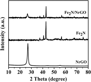
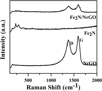
XRD and Raman spectra are used to characterize the composite composition. The XRD patterns of Fe2N/NrGO, Fe2N, and NrGO are exhibited in Fig. 2. For the composite, the peaks at 2θ = 38.5, 40.71, 43.18, 56.17, 68.2, and 75.8° are indexed to the (110), (002), (110), (112), (300), and (113) planes of Fe2N [(JCPDS) no.89-3939], respectively. The diffraction peak at 2θ = 26.4° is ascribed to the graphite (002) plane. Reference Zhang, Lu, Hao, Yang and Tang25 Fig. 3 shows the Raman spectra of Fe2N/NrGO, Fe2N, and NrGO, respectively. Below 1000 cm−1, the peaks of Fe2N/NrGO perfectly match the peak of pure Fe2N. The wavelengths at 1310 cm−1 and 1595 cm−1 indicated the disordered D and G band of carbon that proved the formation of Fe2N/NrGO composite at the same time. Reference Xie, Li, Zhang, Zhang, Wang, Zhang, Pan and Xie26 So, Fe2N/NrGO composite is obtained by the facile sol–gel method.
The XRD patterns of NrGO, Fe2N/NrGO, and Fe2N.

The Raman shifts of NrGO, Fe2N/NrGO, and Fe2N.

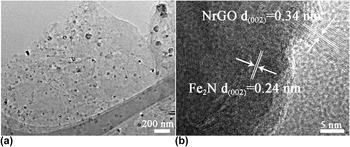
The microstructure of Fe2N/NrGO can be observed from TEM images. It can be seen in Fig. 4(a) that the monodispersed Fe2N nanoparticles with size of about 30 nm were embedded on the surface of NrGO. When Fe2N/NrGO composites are obtained, the graphite oxide layers remain flat, and all the Fe2N nanoparticles grew on the surface of NrGO, no separated Fe2N nanoparticles without NrGO could be found. From the high-resolution TEM (HRTEM) image [Fig. 4(b)], we can observe the plane distances of 0.24 nm and 0.34 nm, which corresponded to the (002) crystal facet of Fe2N and (002) crystal facet of NrGO, respectively. Reference Xiao, Sk, Thia, Ge, Lim, Wang, Lim and Wang27 Iron nitride is a kind of good catalyst, but monodispersed iron nitride nanoparticles could be aggregated easily during the high temperature synthesis process. To solve this problem, we use NrGO as conductive substrate, which makes the iron nitride nanoparticles distribute uniformly on the surface of NrGO. This could get the low resistance for the electron transfer during the HER process. So we think this kind of small size, uniformly-distributed iron nitride nanoparticles/NrGO possessed a great advantage for HER.
(a) TEM images of Fe2N/NrGO and (b) the HRTEM image of Fe2N/NrGO.

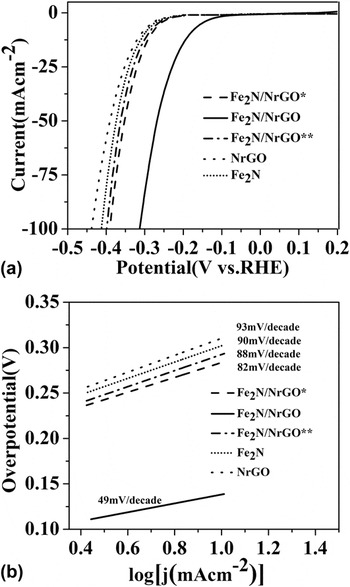
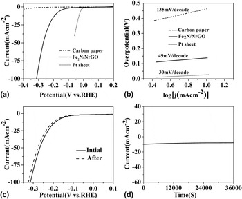
To obtain the best catalytic performance of Fe2N/NrGO composite for the HER measurement, composite with different Fe2N and NrGO ratio has been prepared. Figure 5 shows the polarization and Tafel curve of Fe2N/NrGO with different ratio. It can be seen that when we add 1 mol Fe(OH)3 sol to 1 g GO, the obtained catalytic sample (named Fe2N/NrGO) displayed the best catalytic performance than any other samples (Fe2N/NrGO* and Fe2N/NrGO**). Its overpotential is minimal and the current density is the largest. Also, the catalytic performance of Fe2N/NrGO is far better than that of single Fe2N or NrGO alone. So, the best composite sample Fe2N/NrGO is used for the below measurement. As a conventional HER catalyst, Pt sheet has excellent catalytic performance whose overpotential tends to zero [Fig. 6(a), green curves]. As a HER inert material, carbon paper shows very weak catalytic performance, but it has good conductivity, it is a good substrate for HER [Fig. 6(a), black curves]. The Fe2N/NrGO composite structure has an effective catalytic performance with an overpotential of 94 mV to reach the current density of 10 mA/cm2 [Fig. 6(a)], which is also smaller than the data for hierarchical nanostructure iron based sample FeNi3N/Ni foam (202 mV), Reference Zhang, Xiao, Xie, Liang, Chen and Tang14 Ni3FeN nanoparticles (158 mV) Reference Jia, Zhao, Chen, Shang, Shi, Kang, Waterhouse, Wu, Tung and Zhang15 and binary nickel–iron nitride nanoarrays (180 mV) Reference Jiang, Li, Lu, Sun and Duan16 reported in the previous literature. The details of HER mainly include protons combination with Fe2N, generation of hydrogen atoms in the surface of Fe2N, and hydrogen release. Because nitrogen-doped rGO has many functional groups that are easier to combine with iron ionics, Fe(OH)3 could be monodispersed on the surface of NrGO, which exposed more catalytic active sites for improved HER efficiency. The monodispersed Fe2N nanoparticles could fully contact with the protons of electrolyte, NrGO conductive substrate could improve the electron transfer, which are advantageous for the reaction between the protons and Fe2N catalysts to bring down HER overpotential, to reduce the Tafel, and to improve the reaction efficiency. Reference Voiry, Yamaguchi, Li, Silva, Alves, Fujita, Chen, Asefa, Shenoy, Eda and Chhowalla28 For further study of the HER activity of the Fe2N/NrGO electrocatalyst, Tafel plots are fitted to the equation η = blog (j) + a, where b is the Tafel slope and j is the current density. Figure 6(b) indicates that the Tafel slope of Pt is about 30 mV/dec, which is in accordance with the literature values. The Tafel slope of Fe2N/NrGO is around 51 mV/dec, which is smaller than that of hierarchical nanostructure iron based sample FeNi3N/Ni foam (98 mV/dec), Reference Zhang, Xiao, Xie, Liang, Chen and Tang14 and binary nickel–iron nitride nanoarrays (101 mV/dec). Reference Jiang, Li, Lu, Sun and Duan16 The HER dynamic process belongs to Volmer–Heyrovsky mechanism, and the rate-limiting step of hydrogen is electrochemical desorption. Reference Bockris and Potter29–Reference Shi, Pu, Liu, Asiri, Hu and Sun31
(a) Polarization curves for different proportion of Fe2N and NrGO with a scan rate of 5 mV/s. (b) Tafel plots for different proportion of Fe2N and NrGO with a scan rate of 1 mV/s.

(a) Polarization curves for Fe2N/NrGO, carbon paper, and Pt in 0.5 M H2SO4 with a scan rate of 5 mV/s. (b) Tafel plots for Fe2N/NrGO, carbon paper, and Pt with a scan rate of 1 mV/s. (c) The polarization curves of Fe2N/NrGO before and after 10 h in 0.5 M H2SO4 solution. (d) Cycling stability of Fe2N/NrGO at an overpotential of 120 mV.

HER electrochemical stability is also an indispensable standard to evaluate the catalyst properties. The HER electrochemical stability of Fe2N/NrGO nanocomposite is tested using chronopotentiometry [Figs. 6(c) and 6(d)]. The current density of Fe2N/NrGO only slightly decreased a little after 10 h, which indicated that Fe2N/NrGO composite possesses excellent electrochemical stability [Fig. 6(c)]. Furthermore, the catalytic times of Fe2N/NrGO was carried out at a fixed potential of 120 mV. It could be seen that the current density at 10 mA/cm2 remained relatively stable for 10 h [Fig. 6(d)]. So, the good durability of Fe2N/NrGO catalyst shows promise for practical applications over a long period.
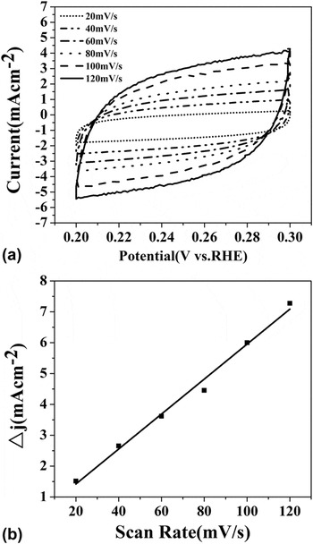
Generally, the exchange current density of catalysts is proportional to the catalytic active area. The catalytic active area is conventionally estimated by measuring the capacitance of the double layer at the solid–liquid interface via a simple cyclic voltammetry (CV) method. The current density was responded under the potential range of 0.2–0.3 V (versus RHE) with different scanning rates from 20 to 120 mV [Fig. 7(a)]. Then, the curves are obtained by plotting the Δj = j a − j c at a given potential (0.25 V versus RHE) against the CV scanning rates [Fig. 7(b)]. The capacitance of Fe2N/NrGO electrode is 56.6 mF/cm2, which means that Fe2N/NrGO electrode possessed relatively high catalytic active area. Reference Conway, Birss and Wojtowicz32 It is because the obtained nanocomposite possessed two merits, the more catalytic activity sites of Fe2N and fast electron transfer of NrGO.
(a) CVs for Fe2N/NrGO with different rates from 20 to 120 mV/s2. (b) The capacitive current at 0.25 V as a function of scan rate for Fe2N/NrGO (Δj 0 = j a − j c).

Electrochemical impedance spectroscopy (EIS) was further carried out at HER overpotential of 360 mV to illustrate the relative enhanced electron transfer. The Nyquist plots of Fe2N/NrGO, carbon paper substrate and Pt electrode are shown in Fig. 8. Experimental data were fitted with the equivalent circuit of R s (R ctCPE), where R s represents the ohmic resistance, R ct reflects the charge transfer resistance between Fe2N/NrGO and the electrolyte interface, CPE is a constant phase element. Reference Kubisztal, Budniok and Lasia33,Reference Liao, Wang, Xiao, Bian, Zhang, Scanlon, Hu, Tang, Liu and Girault34 Generally, a smaller R ct means a faster charge transfer. The Fe2N/NrGO electrode displays a smaller R ct than that of Fe2N, NrGO and carbon paper, only a little inferior than that of Pt. It indicated that Fe2N/NrGO electrode could provide a faster electron transfer than that of carbon paper, which is due to the combination of Fe2N and NrGO that makes the electron transfer faster.
Electrochemical impedance spectra (EIS) of Fe2N, NrGO, Fe2N/NrGO, carbon paper, and Pt catalyzed HER at overpotential of 360 mV.

IV. CONCLUSION
In this work, a facile and efficient method has been developed to synthesize monodispersed Fe2N nanoparticles/NrGO composite as a cheap and highly efficient catalyst for the hydrogen evolution reaction (HER). With the controlled ratio, monodispersed Fe2N/NrGO composite has high HER catalytic activity and great stability with a small onset overpotential of 94 mV to reach current density of 10 mA/cm2, and its Tafel slope is 51 mV/dec. It could be attributed to the specific composite structure that possessed two merits: more catalytic active sites of Fe2N nanoparticles and fast electron transfer of NrGO. Moreover, this kind of synthetic route could be extended to synthesis iron carbide and iron sulfide for greater performance catalyst for HER.
ACKNOWLEDGMENTS
We gratefully acknowledge the support of this research by the National Natural Science Foundation of China (21473051) and the Excellent Youth of Common Universities of Heilongjiang Province (1252G045).