I. INTRODUCTION
The growth of millimeter-wave identification system (MMID) is found vital due to higher bandwidth requirement, interference-free spectrum, compact size, low cost, and power consumption. A MMID reader can be used for high data rate applications such as the next generation wireless personal area network/local area network (WPAN/LAN), intelligent highways and human implants. The MMID systems are also cost-effective and support small-size identification tags [Reference Pursula1–Reference Ijaz4]. The 60 GHz band is an unlicensed spectrum with a 7 GHz bandwidth (57–64 GHz), which can support high-speed and high-capacity wireless links. It is considered to be an interference-free band due to the high O2 absorption of approximately 14 dB/km. Although such a high attenuation factor limits the communication range, it also reduces the effect of interferences significantly and increases the security. The 60 GHz band supports a compact size reader and tag, for instance, a dipole antenna on a low-temperature co-fire ceramic (LTCC) substrate at this frequency is almost 25 times smaller than its counterpart at 2.4 GHz, shown in Fig. 1. In fact, the entire reader can be implemented on a single compact-sized wafer.
Dipole antenna at 2.4 and 60 GHz using the same substrate material.

Among the various beamforming methods, a technique utilizing a Rotman lens is a viable solution due to its ease of implementation and integration with available fabrication technologies for integrated circuits. A properly designed Rotman lens can readily support the required beam scanning range and resolution to meet the design objectives. A 60 GHz Rotman lens feeding a microstrip patch antenna array can increase the communication range while supporting location positioning.
In this paper, a low phase error Rotman lens combined with a microstrip patch antenna array is proposed as a transceiver for high-speed applications. In the proposed scheme, λ/4 radial stubs are utilized as virtual grounds to terminate the dummy ports. The lens and antenna array can be fabricated back to back using a multilayer LTCC substrate to reduce the size of the reader. Simulations were carried out using high-frequency structure simulator and Agilent CAD tools (ADS, Genesys and Empro) for three-dimensional (3D) full-wave simulations to ensure the accuracy of the results and to optimize the geometry of the lens and antenna array.
II. SERIES-FED WIDE BANDWIDTH MICROSTRIP PATCH ANTENNA ARRAY
Series-fed microstrip patch antenna arrays are known for their high gain and directivity, low profile, and ease of implementation with low weight [Reference Wu, Yin and Yuan5]. Microstrip patches are connected in series along their resonant dimension via an arrangement of λ g /2 high-impedance microstrip transmission lines. Therefore, all patches are in the same phase and can resonate at the desired designed frequency. The associated losses of this antenna types is lower than other configurations due to the compactness of the feed arrangement and are therefore the most suitable choice for linear arrays. The main drawbacks of series-fed antenna arrays are: (a) the large impedance variation, (b) the main beam direction over a band of frequencies [Reference Garg, Bhartia, Bahl and Ittipiboon6, Reference Strickland7], and (c) the narrow radiation bandwidth. In this work, the radiation bandwidth is improved four times using periodic open-ended λ g /4 stubs in comparison to the same array without radial stubs.
Direction of the main beam and the scan sensitivity can be determined from (1) to (2) equations [Reference Garg, Bhartia, Bahl and Ittipiboon6]:
 $$d\sin \theta + \sqrt \varepsilon l = \lambda = \displaystyle{c \over f},$$
 $$\displaystyle{{\partial \theta} \over {\partial f}} = - \displaystyle{c \over {df^2 \cos \theta}}, $$
where d is the element spacing, l is the length of the transmission line joining the successive elements, c is the velocity of light, f is the frequency of the operation, and θ is the beam-pointing angle measured from the anticipated direction. In order to reduce the sidelobe level, the width of each patch element (in the non-resonant direction), can be adjusted to control the radiation resistance and the required amplitude distribution. Each resonant element in this configuration can be realized as a two-port microstrip rectangular element with ports located on its non-resonant edges.
The radiated power of a resonant element can be determined from its excitation. The reflection at each junction should be taken into consideration in the calculation of the available power for each radiator. The power radiated by the nth resonant element in the series-fed array configuration can be calculated from (3) [Reference Garg, Bhartia, Bahl and Ittipiboon6]:
 $$V_{rn}^2 = P_{rn} = g_n (1 - g_{n - 1} )(1 - g_{n - 2} ),$$
 $$(1 - g_1 )(1 - \vert \Gamma _1 \vert ^2 )(1 - \vert \Gamma _2 \vert ^2 ) \cdots (1 - \vert \Gamma _n \vert ^2 ),$$
where the normalized radiation conductance, g r , and reflection coefficient, Γ, for a given element are obtained from g r = Z 0/R rad and Γ n = (Z inn − Z fl )/(Z inn + Z fl ). R rad is the radiation resistance of the patch element, Z 0 is the characteristic impedance of the feed line, Z inn is the input impedance at the nth junction, and Z fl is the feed line impedance. From the insertion phase of the patch and connecting transmission line, the phase distribution across the array can be obtained. The relative phase and electrical length at each element of the array can be calculated from the wavelength in the patch and feed line. The radiation pattern and array factor can be calculated as the phase and amplitude are known.
Instead of using conventional step methods or tapers, three open-ended λ g /4 stubs in each λ g /8 portion of the transmission lines are used in order to match the patches with exciting ports and increase the impedance bandwidth of the series-fed microstrip patch antenna array. These capacitive stubs linearize and lower the characteristic impedance of the array to a constant value. They are not required to be 180° electrical length since they do not resonant. More pattern control in the E-plane is possible by controlling the phase of edges using stubs with different lengths. The bandwidth of a series-fed microstrip patch antenna increases significantly if periodic open-ended λ g /4 stubs are used to ensure a constant Bloch wave characteristic impedance [Reference Strickland7].
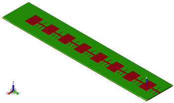
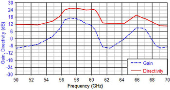
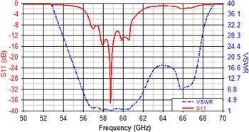
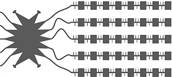
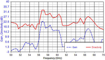
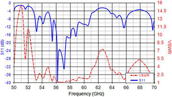
To design a wide bandwidth patch antenna array the characteristic impedance of the patches should be equal to the characteristic impedance of the feed lines [Reference Gong and Volakis8–Reference Lafond, Himdi, Daniel and Haese-Rolland10]. Each section of the loaded transmission line can be modeled as a high-impedance transmission line series with a low-impedance transmission line. Figure 2 shows a schematic diagram of an eight-element series-fed microstrip patch antennas including the λ g /2 transmission lines to connect these elements and the λ g /4 open-ended transmission lines. This array is designed and simulated on the top layer of a multilayer LTCC substrate with dielectric constant (ε r ) of 7.8 and thickness of 121 µM. Figure 3 presents the gain and directivity of series-fed microstrip patch antenna array with maximum of 18 and 25 dB, respectively. S 11 and voltage standing wave ratio (VSWR) of the series-fed microstrip patch antenna array are shown in Fig. 4.
Series-fed microstrip patch antenna array.

Gain and directivity of the series-fed microstrip patch antenna array.

S 11 and VSWR of the series-fed microstrip patch antenna array.

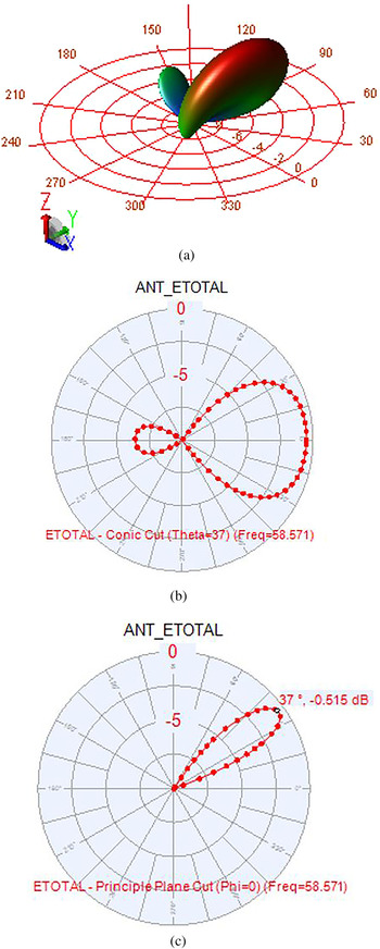
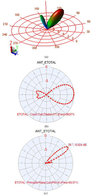
The 3D and 2D radiation patterns of a single microstrip patch antenna array at the center frequency of 58.57 GHz are presented in Fig. 5. The radiation patterns remain generally constant and symmetric across the matched impedance bandwidth.
(a) Full 3D radiation pattern of a single microstrip patch antenna array at a 58.57 GHz center frequency, (b) conic cut, sweep φ, θ = 37°, (c) E-plane, sweep θ, φ = 0°.

III. MICROSTRIP ROTMAN LENS WITH SMALL PHASE ERROR
Passive beamforming is a powerful method for location positioning at the millimeter frequency range. Increasing the directivity with a microstrip patch antenna array at the millimeter wave frequency band lowers the design complexity and reduces the costs. A Rotman lens is designed at the center frequency of 60 GHz for radio frequency identification (RFID) applications in this work. Five beam ports were chosen to allow for a wide range of beam steering with a small amount of phase error. A scan angle of 30° has been selected to cover an azimuthal angle of 60° at a −6 dB antenna radiation pattern to support a wide scanning capability. The antenna beam pattern is chosen to be approximately 15° at −3 dB to allow a beam overlap. The array element spacing along the outer contour was chosen to be 0.5λ 0. Element spacing determines the microstrip patch antenna row spacing and eventually the desired beamwidth.
To keep the geometry compact, the scan angle φ has been selected to be the same as the focal angle α. To implementation the structure, the same substrate with a dielectric constant (ε r ) of 7.8 and thickness of 121 µM as the series-fed microstrip patch array antenna is used. The LTCC substrate has a loss tangent of 0.001. The low line losses as well as competitive manufacturing costs are the main advantages of LTCC for RF and microwave applications.
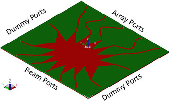
After the initial design objectives were set, the lens geometry was simulated with a finite-difference time-domain simulator and the results were confirmed with a finite-element method analysis. The design parameters including geometric dimensions and losses were then optimized using sidelobe levels, phase errors, and sidewall curvature as cost functions. A 3D view of the designed lens is shown in Fig. 6.
3D view of the designed Rotman lens geometry.

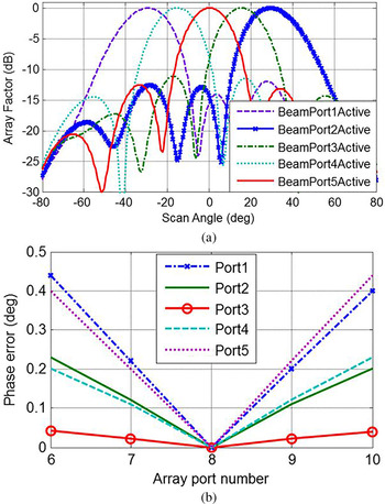
The main parameter for the Rotman lens is its array factor which presents the beam direction, angle, and level of side lobes. The array factor is shown in Fig. 7(a) for different beam port excitations which has sidelobes of less than −12 dB at a 60 GHz center frequency. The array factor analyses indicate that medium beam transmission lines and routed medium array transmission lines with small tapered flare angle are the best choices to lower the sidelobes level.
(a) Synthesized array factor for beam ports, (b) beam to array phase error for the different beam ports excited.

An important design factor is the accuracy in the beam steering and the maximum phase error associated with the different beam ports excitation. Phase error can be determined by comparing electrical lengths along two different paths from a given beam port through the lens [Reference Rotman and Turner11–Reference Singhal, Gupta and Sharma14]. The first path travels along each of the off-axis array ports. As for the second path, it begins at the same beam port but travels through the array curve center.
The beam to array phase error for all the ports of the proposed scheme are shown in Fig. 7(b); it is always zero for the center array port as it is the calculation reference point. All beam and array port locations are optimized to produce minimum phase errors. The maximum beam to array phase error for all beam ports was found below 0.45°, and the average phase error is lower than 0.25° which is a considerable improvement compared with the reported phase error in other works [Reference Lee, Kim and Yoon15, Reference Lee, Kim, Cho and Yoon16].
A) Terminating the dummy ports using λ/4 radial stubs
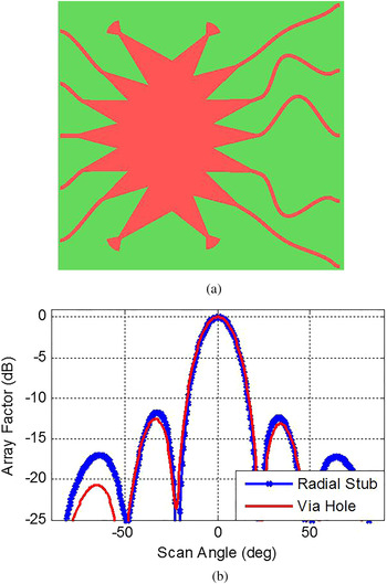
To further reduce the costs of fabrication, λ/4 radial stubs, instead of via hole through the substrate, are used to terminate the dummy ports of the proposed lens. This also reduces the costs of testing by eliminating the need for costly connectors for each dummy port during the test phase. Figure 8(a) shows the top view of the proposed lens and Fig. 8(b) shows the array factor of the proposed Rotman lens with radial stubs for terminating the dummy ports. A comparison to the via-hole termination design (shown in Fig. 6) with the center beam port excited.
(a) Top view of the proposed lens using radial stub for terminating the dummy ports, (b) array factor using radial stub and via hole through the substrate.

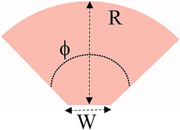
The array factors of the lens for the center beam port show that the main lobes are unaffected while the main sidelobe levels increased almost by 0.5 dB. In addition to the cost reduction, the λ/4 radial stub reduces the area overhead. The stubs are connected in series with 50 Ω tapers. The geometry calculation of the radial stub is illustrated below in Fig. 9.
Geometry of the radial stub.

The width, W, of the stub is set to be 50 Ω to match with the taper of the lens shown in Fig. 9. The length, R, is chosen to be λ/4, which makes an open circuit stub act as a short circuit. The angle, ϕ, is limited to a range: ϕ min < ϕ < 170°; these limitations support practical geometries. The minimum angle, ϕ min , is limited to where the chord across the arc is less than W and can be calculated from: ϕ min = 2 × arcsin(0.5 W/R). The ϕ is chosen to be 70° to meet the design requirement while reducing sidelobe levels.
IV. MICROSTRIP SERIES ANTENNA ARRAY FED BY THE ROTMAN LENS
One approach to reduce the costs of an RFID reader or wireless communication systems is to employ micro electro mechanical systems (MEMS) technology utilizing low-cost materials and to omit any analog or digital circuitry devices. A microwave beamformer, such as a Rotman lens, offers a path delay mechanism to form the desired beamforming without any extra analog or digital circuitry. The lens can be combined with a highly directional series-fed antenna array utilizing the same technology and substrate to ease the packaging complexity and reduce the fabrication costs. These two components provide an inexpensive and compact solution to implement a 60 GHz transceiver. Figure 10 shows the geometry of the proposed lens connected to a series-fed microstrip patch antenna arrays. Figures 11 and 12 present the gain, directivity, return loss, and voltage standing wave ratio of the proposed lens connected to the arrays of antenna. In a uniformly excited planer antenna array with equal space of λ/2, the directivity and gain are highly depended on the element spacing and the number of elements.
Rotman lens connected to five series-fed microstrip eight-patch antenna arrays.

Gain and directivity of the planner antenna connected to Rotman lens.

S 11 and VSWR of the planner antenna connected to Rotman lens.

Far-field 3D and 2D radiation patterns of a Rotman lens combined with five microstrip patch antenna arrays at a center frequency of 58.57 GHz for an excited center beam port are presented in Fig. 13.
(a) Full 3D radiation pattern of a Rotman lens combined with five microstrip patch antenna arrays at 58.57 GHz center frequency, (b) conic cut sweep φ, θ = 37°, (c) E-plane, sweep θ, φ = 0°.

A) A fabrication alternative
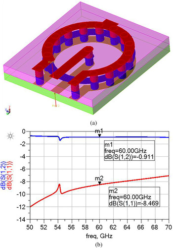
The wafer area costs could further be reduced by fabricating the Rotman lens and antenna back to back on different sides of a multilayer LTCC substrate. This approach enhances the compactness of the whole package considerably as most of the area is consumed by the antenna especially if the number of patches is increased in the arrays; however, the fabrication cost increases due to many via holes through the substrate. From Fig. 10, for an array of eight microstrip patch antennas, the back-to-back design approach would cut the wafer size in half. The transition between layers can be done either electrically using vias or magnetically coupled slots. The power loss between layers is critical because it can reduce the efficiency of the entire system. To minimize this effect, via holes in a coaxial structure are realized to follow the fabrication process rules of the multilayer LTCC substrate. Figure 14 shows the insertion loss and the return loss of a via hole using two 121 µM layers of the LTCC substrate at the center frequency of 60 GHz.
(a) Two-layer coaxial via-hole structure, (b) insertion and return losses of the coaxial via hole.

V. CONCLUSION
A new design technique to realize an efficient microstrip Rotman lens combined with a wide bandwidth patch antenna array for 60 GHz applications is presented in this work to support location positioning and increase the communication range through beam steering. The progressive phase delay is realized independent of the length of transmission lines to reduce the design complexity while improving the phase error. A wideband microstrip patch antenna array is developed with high gain, directivity, and bandwidth using λ/4 microstrip transmission lines. Four radial stubs are used as virtual grounds to terminate the dummy ports instead of via holes in the Rotman lens to reduce the costs of fabrication and testing.
ACKNOWLEDGEMENT
The authors would like to thank the research and financial supports received from Natural Sciences and Engineering Research Council (NSERC) of Canada and CMC Microsystems.
 Ali Attaran received the B.A.Sc. and M.A.Sc. degrees in Electrical Engineering in 2005 and 2008 and also his Ph.D. degree in Electrical Engineering at the University of Windsor, Windsor, ON, Canada in 2015. RFID, Radar, Analog, Digital, RF and Microwave-Integrated Circuit Design, and MEMS are his research interests. He is currently working as a Research Assistant in Research Center for Integrated Microsystems (RCIM) laboratory.
 Rashid Rashidzadeh received the B.S.E.E. degree from Sharif University of Technology, Tehran, Iran, in 1989 and the M.A.Sc. and Ph.D. degrees in Electrical Engineering from the University of Windsor, Windsor, ON, Canada in 2003 and 2007, respectively. From 1990 to 2000 he worked in industry where he was involved with the design and test of analog and RF circuits for telecommunication systems. He is currently with the Electrical and Computer Engineering Department at the University of Windsor. His research focuses on design and test of analog/RF cores in mixed-signal system-on-chip environments.
 Roberto Muscedere received his Ph.D. (2003), M.A.Sc. (1999), and B.A.Sc. (1996) degrees from the University of Windsor, ON, Canada in Electrical and Computer Engineering. During most of this time he was also the laboratory manager for the Research Centre for Integrated Microsystems, formally VLSI Research Group.