


I. INTRODUCTION
Laboratory-scale X-ray diffractometers may be used to analyze various samples, such as a powder, film, fiber, or solid. By changing attachments, they can also be used for various purposes, such as qualitative and quantitative analysis, in situ measurement during heat treatment, and pole figuring. The goniometer radius of an apparatus that is used for these various types of measurements must have a long length to enable the changing of optical components and to obtain special resolution. While the resolution is better with a larger, rather than a smaller, goniometer radius, there is an inverse relationship between the intensity and the resolution. Thus, to obtain high intensity data, the goniometer radius must be short. Bench-top X-ray diffractometers have short-length goniometer radii because of their limited size. An additional advantage of bench-top X-ray diffractometers is their portability; they can be operated using a 100 V power supply.
Bench-top X-ray diffractometers are ideal for the crystalline phase analysis of cement, because it must be analyzed in a short time because of its rapidly changing compositions, and high X-ray intensity data may be obtained. There are various types of cements with wide ranging compositions depending on the application, such as buildings (Pulselli et al., Reference Pulselli, Simoncini, Ridolfi and Bastianoni2008), tunnels (Ba et al., Reference Ba, Qian and Zhuang2012), dams (Yang, Reference Yang2004), and bridges (Gebauer and Harnik, Reference Gebauer and Harnik1975). For example, the cement used to construct tunnels located in seawater must solidify rapidly. Cement consists of clinker (Kristmann, Reference Kristmann1979), calcium sulfate hydrate, aggregate, and water. Clinker is the major raw material and is made from limestone, and contains residues from the production process, such as lime (CaO). It is well known that the composition of cement changes with time, in part because of the presence of lime. The crystalline phases in cement can also change very easily and quickly to other phases depending on the environment. The quantity of lime in cement indicates the degree of calcination; over time, the lime can change to portlandite (Ca(OH)2) or calcite (CaCO3) through reaction with moisture or carbonic acid present in the atmosphere, respectively. These changes can lead to damage and degradation of the concrete. The surface of reinforced concrete, for example, is covered with goethite (FeO(OH)) to prevent corrosion. If portlandite is produced through the reaction of lime and moisture, the reinforced concrete can be degraded by neutralization. Therefore, the composition of cement must be known. Recently, high intensity data have been obtained in a short time by employing a silicon strip detector in place of a scintillation counter in an X-ray diffractometer. Therefore, Rietveld refinement data may be obtained rapidly and easily.
Here an improved apparatus for X-ray diffraction that is designed for rapid measurement is described. Cement may be analyzed within 5 min, and the composition determined using the Rietveld refinemenet technique.
II. EXPERIMENTAL
A. Apparatus
X-ray diffractometry was performed by using a Rigaku MiniFlex600 diffractometer equipped with a vertical goniometer (radius of 150 mm), a one-dimensional silicon strip detector D/teX Ultra, CuKα radiation with a Ni filter operating at a tube voltage of 40 kV and a tube current of 15 mA. The optical setup was in the Bragg-Brentano focusing geometry with a variable divergence slit and a 13-mm receiving slit. The samples were rotated at 60 rpm during the measurement to mitigate the preferred orientation.
Data for the Rietveld refinement were recorded in the 2θ range from 5 to 65° at 0.02° intervals and a scan speed of 25°/min. The diffraction patterns were analyzed using the Rietveld refinement method and PDXL2 software. The parameters for the initial structures of the phases in the samples were obtained from the literature: alite (Torre et al., Reference Torre, Bruque, Campo and Aranda2002), belite (Tsurumi et al., Reference Tsurumi, Hirano, Kato, Kamiya and Daimon1994), ferrite (Waerenborgh et al., Reference Waerenborgh, Rojas, Vyshatko, Shaula, Kharton, Marozau and Naumovich2003), aluminate (Mondal and Jeffery, Reference Mondal and Jeffery1975), periclase (Tsirelson et al., Reference Tsirelson, Avilov, Abramov, Belokoneva, Kitaneh and Feil1998), and lime (Huang et al., Reference Huang, Chmaissem, Caponi, Chaillout, Marezio, Tholence and Santoro1986).
A centrifugal-type ball mill (P-7; Fritsch GmbH) with an agate bowl (45 ml) was used for grinding the samples.
B. Samples
The clinker reference sample (NIST 2686 standard reference material) was obtained from the National Institute of Standards and Technology. Ordinary Portland cement was used for quantitative determination of the lime content. The cement used for observation of the calcification process was a rapidly hardening cement.
C. Quantitative analysis of the lime content in cement
Quantitative analysis of the lime was conducted in accordance with the JCAS I-01 method issued by the Japan Cement Association, which is a titrimetric method using ethylene glycol. Approximately 1 g of cement was mixed with 40 ml of ethylene glycol and heated at 80 °C, followed by the addition of phenolphthalein as an indicator. The eluted lime in the mixing material was titrated with ammonium acetate.
III. RESULTS AND DISCUSSION
A. Apparatus for measurement of cement
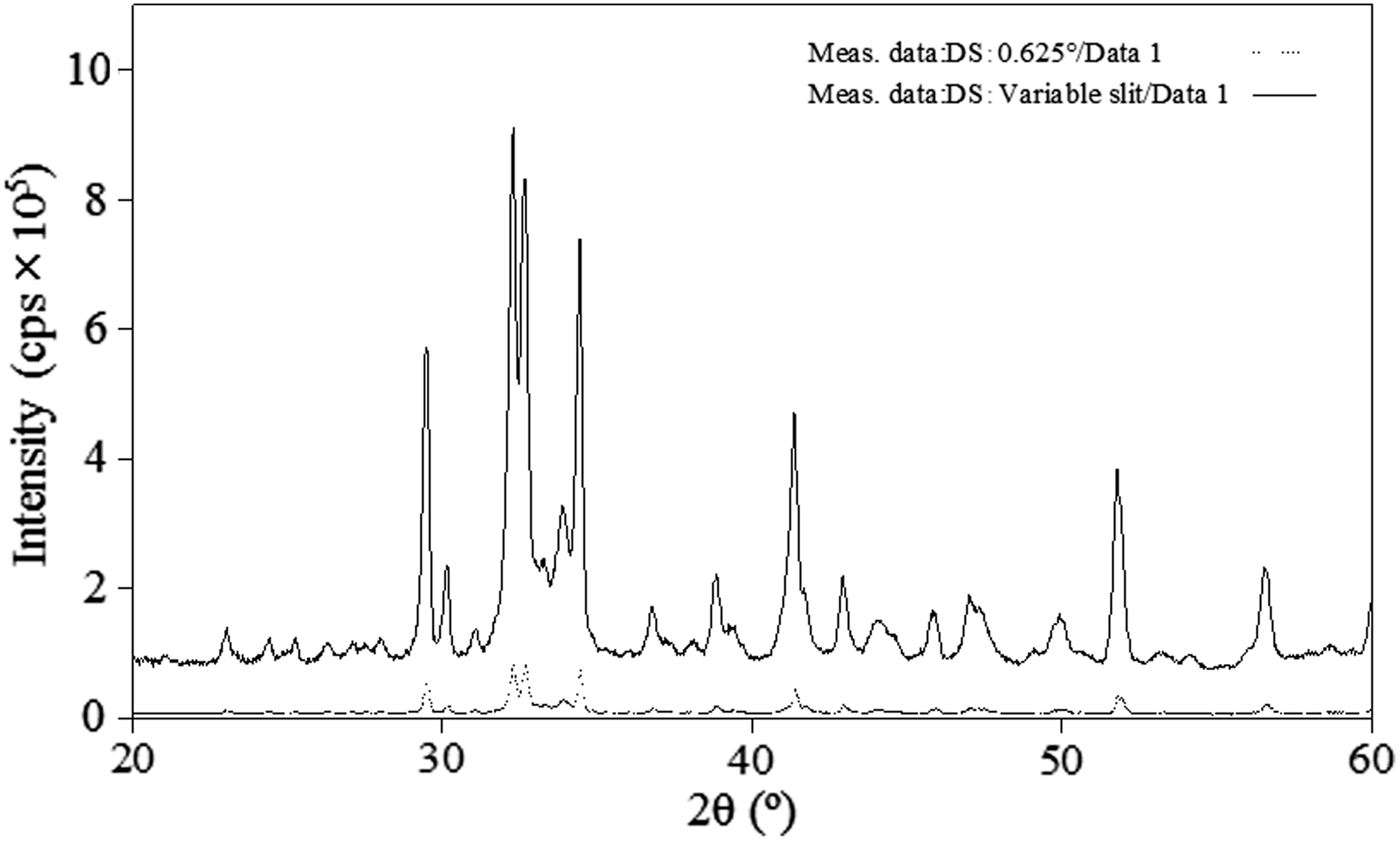
For the rapid measurement of a powder, an X-ray diffractometer was devised with the following features, as can be seen in the photograph presented in Figure 1. The apparatus is 560 mm wide, 460 mm deep, and 700 mm high, i.e., it is a bench-top X-ray diffractometer. A 100 V power supply and cooling water are needed to operate the bench-top X-ray diffractometer, which may be used as a portable instrument. The apparatus consists of a 600 W CuKα radiation with a Ni filter, soller slits, a divergence slit, a sample holder, a variable knife edge, a scattering slit, a receiving slit, and a detector. The goniometer radius of the bench-top X-ray diffractometer was set at 150 mm. The resolution of a one-dimensional silicon strip detector is equal to that of a scintillation counter when it is used with a 0.1 mm receiving slit. In this diffractometer, high resolution can be obtained by using a one-dimensional silicon strip detector, because a divergence slit was used in the variable mode in order to obtain high X-ray intensity data. The area illuminated by the X-rays was held constant by the variable slit to 2θ = 67°. A comparison of the X-ray intensities obtained using the variable slit and a fixed slit is shown in Figure 2. The intensity with the variable slit is approximately eight times stronger than that obtained with the fixed slit. For detection, a high-speed one-dimensional silicon strip detector was used instead of a scintillation counter because it can obtain high intensity data approximately 100 times more rapidly. A comparison of the X-ray intensities obtained with the one-dimensional silicon strip detector and a scintillation counter is shown in Figure 3. With the incorporation of these components into the modified bench-top diffractometer, it was possible to collect X-ray diffraction measurements for cement within 5 min. In addition, a variable knife edge, which is effective for eliminating the effect of air scattering on diffraction data, can be used with the bench-top X-ray diffractometer; however, it is possible to cut off the X-ray diffraction reflections at high 2θ angles with a fixed knife edge. Thus, the system was designed to address this issue. The variable knife edge is automatically moved to adjust the distance between the sample surface and the knife edge during the measurement, such that the distance between the sample and the knife edge at high 2θ angles was longer than that at low 2θ angles (Figure 4). Furthermore, the sample can be rotated during measurement to determine the average diffraction intensities.
Photograph in MiniFlex600 optics system.

Comparison of the reflection intensities obtained using fixed (0.625°) and variable divergence slit. (The data of variable slit was converted to the fixed slit mode.)
Comparison of reflection intensities in Si material using a one-dimensional detector (solid line) and a scintillation counter (dotted line).

Schematic diagrams of the goniometer at (a) low and (b) high 2θ (°) angles. The distance between the sample and the variable knife edge is greater in (b) than in (a).

B. Quantitative analysis of the crystalline phases in the NIST standard and cement
The Bogue method (Bogue, Reference Bogue1929) is a theoretical method for quantitative analysis of components in cement. Bogue proposed an equation for calculating the quantities of diffrerent components in cement using elemental information. With the Bogue method, the contents of major chemical compounds in the clinker, such as alite or hatrurite (3CaO·SiO2), belite or larnite (2CaO·SiO2), ferrite or brownmillerite (4CaO·Al2O3·Fe2O3), and aluminate (3CaO·Al2O3), can be calculated; however, this method cannot be used to determine the content of other components in cement, such as lime and portlandite. Scanning electron microscopy (SEM) (Ghose and Barnes, Reference Ghose and Barnes1979) with the counting method is thus used for the evaluation of cement, but this method is time consuming. On the other hand, with X-ray diffraction, the crystalline phases in cement may be identified, and the Rietveld refinement technique (Rietveld, Reference Rietveld1969) can be used for the quantitative analysis of these phases.
Cement composition should be measured rapidly, because the phases change with time. With the newly modified X-ray diffractometer, it was possible to obtain measurements in 3 min using the various functions of the apparatus. The Rietveld refinement technique is a pattern-fitting method for calculating crystalline structures, and may also be used for determination of the weight fraction of the crystalline phases in a sample using a scale factor for each phase. The quantitative analysis of the major components in the NIST 2686 standard reference material was performed using the Rietveld refinement technique. The pseudo-Voigt function (Toraya, Reference Toraya1990) was used for the Rietveld refinement integrated in the software program PDXL2. The results of the Rietveld refinement are shown in Figure 5, and the analytical results for alite or hatrurite (C3S), belite or larnite (C2S), ferrite or brownmillerite (C4AF), aluminate (C3A), and periclase (MgO) are shown in Table I. The quantitative results for the major components are in good agreement with the certified values of the NIST 2686 standard reference material. The quantitative analyses of the lime content in two cements were also conducted by using the Rietveld refinement technique, as well as the titrimetric method. The results of these analyses are shown in Table II. It can be clearly seen in the table that the quantitative determination for the lime content in the two cements using the modified bench-top diffractometer were in agreement with the quantitative values obtained via the titrimetric method.
Observed (solid line) and calculated (dotted line) diffraction patterns and the difference curve with Rietveld refinement for the NIST 2686 reference material. Hat: Hatrurite (C3S), Bel: Belite (C2S), Bro: Brownmillerite (C4AF), Alu: Aluminate (C3A), Per: Periclase (MgO).

Analytical results (mass%) of major components in the NIST 2686 reference material.

(): Standard deviation (3σ).
Analytical results (mass%) of the lime in the cements.

(): Standard deviation (3σ).
C. Observation of the calcification process in rapidly hardening cement
The calcification process in rapidly hardening cement was observed by dropping water on the cement immediately before measurement. Prior to observation of the calcification process, the components of the rapidly hardening cement were analyzed. Alite, belite, ferrite, aluminate, calcite, dolomite (CaMg(CO3)2), quartz (SiO2), gypsum (CaSO4·2H2O), anhydrite (CaSO4), and bassanite (CaSO4·0.5H2O) were identified (Figure 6), and the composition was calculated using the Rietveld refinement method. In clinker, alite, belite, ferrite, and aluminate contribute to the calcification process. Not surprisingly, in the rapidly hardening cement, alite, which rapidly influences calcification, was the dominant phase. The calcification process was observed by evaluating the changes in the diffraction patterns over time, as shown in Figure 7. Notably, diffraction reflections for ettringite ((3CaO·Al2O3·3CaSO4·32H2O)) were clearly observed after approximately 40 min. Ettringite is a crystalline phase related to the calcification process, and is produced via the reaction of aluminate, gypsum, and water. In the calcification of conventional cement, ettringite is produced over a much longer period of time than that observed in the rapidly hardening cement. In addition, the diffraction reflections for ettringite cannot be observed during the calcification of conventional cement because it is formed in very limited quantities.
Results for the qualitative analysis of the rapidly hardening cement.

Diffraction patterns collected during the calcification of the rapidly hardening cement.

D. Conclusion
An improved bench-top X-ray diffractometer for obtaining high X-ray intensity data was developed. A 600 W CuKα radiation with a Ni filter, variable divergence slit, and one-dimensional silicon strip detector were used in the bench-top X-ray diffractometer, which makes it possible to collect high X-ray intensity data more readily than is possible with a conventional floor-type diffractometer. The utility of the improved instrument was demonstrated by analyzing various cements. The results of the quantitative analysis of the components in a NIST standard reference material using the Rietveld refinement technique were in good agreement with the certified values, and the quantitative values calculated for the lime content in regular cement as determined by using the Rietveld refinement technique were also in agreement with the values obtained using the titration method. In addition, the calcification process in rapidly hardening cement was observed immediately after the cement was mixed with water. The production of ettringite during the calcification process was detected based on evaluation of the changing reflections in the diffraction pattern of the cement over time.



