

Introduction
Implantation of bone-anchored hearing devices in children is a widely accepted technique for external ear deformities like microtia and malformation of the external auditory canal. These bone-anchored hearing devices are also used in children with conductive hearing loss due to chronic otitis media who are unable to wear conventional hearing aids. The technique is based on the principle of osseointegration of a titanium screw into the skull for transmission of the sound. Improvement in speech recognition with bone-anchored hearing devices over conventional hearing aids is well documented.Reference Mylanus, Snik, Cremers, Jorristma and Verschuure1
Case report
An otherwise fit and well 12-year-old boy was referred from the audiology department with deterioration in hearing and an abnormal-looking tympanic membrane. He wore bilateral hearing aids. He had undergone myringoplasty on the left side at age seven years, for recurring discharge from a perforation.
He was reviewed in the ENT out-patients department and found to have bilateral chronic otitis media (adhesive type). He had a mixed hearing loss, with an average bone conduction of 40 dB bilaterally and air conduction 60 dB on the right and 80 dB hearing loss on the left.
The patient continued to wear his conventional hearing aids and was followed up in the clinic regularly. During the course of the follow up, he started developing bilateral recurrent ear infections, persistent on the right side, and this made the use of hearing aids problematic. He was assessed for bone-anchored hearing device suitability while waiting to undergo right middle-ear exploration. Following the assessment by the audiologist, it was concluded that the patient would benefit from a bone-anchored hearing device compared to the current conventional hearing aid.
The patient was 15 years old when he underwent endoscopic-assisted atticotomy. He was noted to have two separate cholesteatoma sacs, one in the lateral semicircular canal and the other in the anterior epitympanum. The lenticular process of the incus and the anterior crus of the stapes were eroded. The right attic defect was repaired using conchal cartilage with perichondrium.
In order to implant the bone-anchored hearing device, the patient had three pilot holes drilled in different areas of the skull on the left side for implanting the abutment; however, none were more than 2.5 mm in depth and hence the procedure was abandoned.
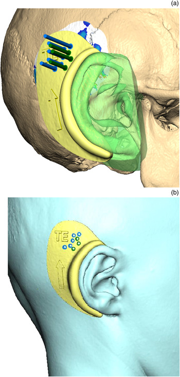
A computed tomography (CT) scan of the temporal bone was requested. With the help of the reconstructive maxillofacial laboratory, a colour-coded map showing the different areas of skull thickness was created (Figure 1). The previous drilling attempts were also identified and marked. A template was created free form using a three-dimensional (3D) system. The engagement area was highlighted and copied, with the post-aural sulcus and helix as landmarks. An ‘offset’ of 2–3 mm was applied to create the body of the splint. The ear anatomy was removed from the splint, using a Boolean operation to create a perfect fitting surface, with holes showing different areas of skull thickness to aid in identifying the appropriate area for implantation during surgery (Figure 2). The patient subsequently underwent successful implantation of the bone-anchored hearing device using the template (Figure 3).
Original skull with colour map (red area = 6 mm bone thickness, blue = 3 mm bone thickness, green = 4 mm bone thickness, white = less than 3 mm bone thickness; black circles indicate previous implant attempt).

(a) & (b) Soft tissue guide upon the soft tissue of the patient (blue holes = 3 mm of bone thickness, green holes = 4 mm of bone thickness). Arrow on guide indicates upright placement. TE = Departmental Template Identifier

Soft tissue guide alone (blue holes = 3 mm of bone thickness, green holes = 4 mm of bone thickness). Arrow on guide indicates upright rotation. TE = Departmental Template Identifier

Discussion
Implantation of bone-anchored hearing devices for conductive hearing loss in children has been shown to be effective in hearing rehabilitation. Current Food and Drug Administration guidelines recommend implantation in patients aged over five years, given the concerns with bone thickness at the implantation site. However, a review of temporal bone CT imaging in children aged 1–5.99 years showed the temporal bone thickness to be greater than 3 mm in all age groups, in normal and diseased ears.Reference Baker, Fanelli, Kanekar and Isildak2 This is in line with another study where the mean bone thickness lateral to the sinodural angle in the atretic ear in children aged less than six years was at least 4.8 mm, with a thickness of 4.1 mm in the non-atretic ear.Reference Ukatu, Desai and Todd3
• A bone-anchored hearing device can be implanted in patients with a chronically discharging ear who are unable to wear conventional hearing aids
• Patients need to be aged over one year and have temporal bone thickness of at least 3 mm for device implantation
• In patients with thin and irregular skull bone, a computed tomography guided three-dimensional template of the temporal bone can be crafted
• This template can help identify an appropriate site for safe bone-anchored hearing device implantation
Shallow cortical bone thickness and exposed dura at the base of the drill hole can lead to failure caused by fixture loss.Reference Lloyd, Almeyda, Sirimanns, Albert and Bailey4
Computer-aided design and manufacturing technology for craniofacial prostheses has been used effectively in various maxillofacial procedures. This system can be used to guide the implant surgery and to project the position of the implant.Reference Ciocca, Fantini, De Crescenzio, Persiani and Scotti5
Our patient did not have any medical conditions that raised concerns regarding temporal bone thickness for implantation. In patients with a skull bone of irregular thickness, 3D mapping of the skull can be undertaken and a suitable area for implantation can be identified with the help of a template (Figure 2), for safe implantation of the abutment.
Conclusion
Bone-anchored hearing devices can be implanted in patients with chronic suppurative otitis media to improve hearing. A CT and 3D reconstruction is an effective way of finding an appropriate site, if a previous implantation attempt has failed.
Competing interests
None declared