1. Introduction
Flow separation resulting in free vortex generation other than from a trailing edge (TE) are very common phenomena in both natural and artificial flow problems, such as for flapping wings (Ellington et al. Reference Ellington, van Den Berg, Willmott and Thomas1996; Birch & Dickinson Reference Birch and Dickinson2001; Muijres et al. Reference Muijres, Johansson, Barfield, Wolf, Spedding and Hedenstrom2008; Zhang Reference Zhang2017), for fixed delta wings (Polhamus Reference Polhamus1966, Reference Polhamus1971; Ma, Wang & Gursul Reference Ma, Wang and Gursul2017), for car aerodynamics (Rao et al. Reference Rao, Minelli, Basara and Krajnovic2018) and for wind turbines (Mao & Sorense Reference Mao and Sorense2018). These vortex structures, essentially formed of continuous vortex sheets, are represented by discrete vortices with specified circulation in discrete vortex simulation (Xia & Mohseni Reference Xia and Mohseni2013), or distributed vorticity in cells in computational fluid dynamics (CFD) (Li & Lu Reference Li and Lu2012) or in experimental measurements (Dickinson & Gotz Reference Dickinson and Gotz1993; Pitt Ford & Babinsky Reference Pitt Ford and Babinsky2013). The integral of the vorticity within and perpendicular to a given element of cross-sectional area gives the circulation of that area element. Each such small area element may be represented by a discrete vortex. Basically, all the vortex elements in the flow field are ‘free’ and convect with the local velocity. The vortex structures in a separated region which may be represented by a cluster of vortex elements can be stabilized under some self-equilibrium conditions (Saffman Reference Saffman1992).
Usually, the free vortices have a great impact on the aerodynamic forces acting on the body (Polhamus Reference Polhamus1971; Li, Dong & Zhao Reference Li, Dong and Zhao2018). For example, they have been shown to be capable of enhancing lift (Polhamus Reference Polhamus1971; Dickinson & Gotz Reference Dickinson and Gotz1993) or generating thrust (Zhang Reference Zhang2017), and they could also reduce lift or increase drag in case of dynamic stall (Akbari & Price Reference Akbari and Price2003) or drag augmentation (Zhang, Wang & Fu Reference Zhang, Wang and Fu2017).
Due to the importance of free vortices on aerodynamic forces, great efforts have been made to develop approaches that establish a relationship between aerodynamic forces and the properties of free vortices. Various methods have been proposed, including integral approaches derived from a momentum method (Wu Reference Wu1981; Saffman Reference Saffman1992; Howe Reference Howe1995; Wu, Lu & Zhuang Reference Wu, Lu and Zhuang2007) and point vortex approaches derived from unsteady Bernouilli or Blasius equations (Pitt Ford & Babinsky Reference Pitt Ford and Babinsky2013; Xia & Mohseni Reference Xia and Mohseni2013).
The majority of existing vortex force approaches, such as the integral approaches in Wu (Reference Wu1981) and Howe (Reference Howe1995), require the vorticity distribution in the entire flow field to be known. For applications without knowledge of the pressure distribution and with only limited information of the data in a truncated domain, e.g. provided by particle image velocimetry (PIV), it is very helpful if only free vortices near the body are required in the vortex force approaches. Some approaches requiring incomplete knowledge of the vorticity distribution have been derived, see for instance Noca, Shiels & Jeon (Reference Noca, Shiels and Jeon1997), Graham, Pitt Ford & Babinsky (Reference Graham, Pitt Ford and Babinsky2017) and Kang et al. (Reference Kang, Liu, Su and Wu2018).
Moreover, it is also useful if a vortex force approach can produce a vortex force map (VFM) that is capable of identifying critical regions and directions for vortex force enhancement or reduction without knowing the flow field, and meanwhile can help interpret the role of various concentrated vortices such as leading edge vortices (LEVs) and trailing edge vortices (TEVs). Such a VFM method has been proposed by Li & Wu (Reference Li and Wu2015, Reference Li and Wu2016), in the framework of two-dimensional (2-D) flat plate flows.
To have an approach that meets the above two requirements, Li & Wu (Reference Li and Wu2018) proposed a VFM method based on Howe's integral force formula. With this approach different stages of force evolution have been associated with the positions of the LEVs and TEVs. For instance, force enhancement and force recovery can be associated with the effects of the LEVs and the TEVs, similarly to the pressure suction analogy of Polhamus (Reference Polhamus1971) for delta wings and for a flapping wing (Dickinson & Gotz Reference Dickinson and Gotz1993). However, this approach has been studied only for 2-D flow of general airfoils, though Li & Wu (Reference Li and Wu2018) provided a short discussion on a possible extension to three dimensions.
Here in this paper, the VFM method is extended to three-dimensional (3-D) unsteady flows. This extension is still based on Howe's integral approach and a force decomposition is performed to make sure that only near-body vortices are needed. Vortex force maps in each spatial direction are produced to identify the force contribution of vortices in different spatial directions. Similar to Li & Wu (Reference Li and Wu2018), CFD is used to provide the velocity/vorticity field. The preliminary study of this method on truncated domains has been done after the validation of this method using CFD data, while the research on the feasibility of this method for application in PIV field, such as systematically decreasing the domain, coarse sampling and using noisy data, is beyond the scope of this work. The starting flow about a delta wing at high angle of attack (AOA) is specially chosen for the demonstration, since both steady attached and detached LEVs are possible flow structures in this case. The empirical force equation by Polhamus (Reference Polhamus1971) and the experimental results by Earnshaw & Lawford (Reference Earnshaw and Lawford1966) are used to test the CFD method. The forces calculated by the 3-D VFM method are validated against those directly obtained from CFD. It is of particular interest to see whether the force evolution still exhibits similar behaviour as in 2-D high-AOA airfoil flow for a high-AOA delta wing whose force is dominated by LEVs, and how the vortex force is influenced by the LEVs.
The extension of the force approach to three dimensions is presented in § 2. Section 3 is devoted to the VFM analysis of a 3-D delta wing, with comparison to 2-D flat plate maps. The application of the vortex force approach to a delta wing at a range of AOAs and different Reynolds numbers is presented in § 4. Concluding remarks are given in § 5.
2. VFM method for 3-D flow
Figure 1 is the schematic diagram of a delta wing configuration in symmetric flow conditions. The free stream velocity  $V_{\infty }$ is started impulsively at
 $t=0$, and it is in the plane of symmetry with an incidence of
 $\alpha$. In the body-fixed frame,
 $x,y,z$ Cartesian axes are defined aligned with the body axes:
 $x$ is along the streamwise/axial direction,
 $y$ is along the spanwise/sideward direction and
 $z$ is along the vertical/normal direction. The force vector acting on the body is composed of a normal component
 $F_{3}$, an axial component
 $F_{1}$ and a lateral component
 $F_{2}$. Alternatively it may be decomposed into a lift component
 $L$, a drag component
 $D$ and a lateral force component
 $F_{S}$. The fluid density
 $\rho$ is constant since we only consider incompressible flow. The velocity of the flow in the body-fixed frame is
 $\boldsymbol{U} =(u,v,w)$ and the vorticity is
 $\boldsymbol{\omega }=( \omega _{x},\omega _{y},\omega _{z})$ with its three components
 \[ \omega _{x}= \frac{\partial w}{\partial y}-\frac{\partial v}{\partial z},\quad \omega _{y}= \frac{\partial u}{\partial z}-\frac{\partial w}{\partial x},\quad \omega _{z}= \frac{\partial v}{\partial x}-\frac{\partial u}{\partial y}. \]
 $(a)$ A schematic diagram of vortex flow and various force components for a 3-D body at an incidence of
 $\alpha$, using a delta wing for demonstration (
 $x$ is along the streamwise/axial direction,
 $y$ is along the spanwise/sideward direction and
 $z$ is along the vertical/normal direction). The force may be decomposed into a lift component (
 $L$), a drag component (
 $D$) and a side force component (
 $F_{S}$) or alternatively as a normal component (
 $F_{3}$), an axial component (
 $F_{1}$) and a side component (
 $F_{2}$).
 $(b)$ The analogy between the normal force of a slender delta wing and that of a 2-D flat plate with steadily growing width.
 $(c)$ Analysis of the contribution of a given vortex to the body force based on Wu's (Reference Wu1981) impulse force formula.

2.1. Basic force expressions in three dimensions
The 2-D vortex force expression for general airfoils in Li & Wu (Reference Li and Wu2018) is
 \begin{equation} F_{k}=\rho \iint_{\Omega } \boldsymbol{\Lambda}_{k}\boldsymbol{\cdot} \boldsymbol{U}\omega \,\textrm{d}\Omega , \end{equation}
where  $\boldsymbol{\Lambda}_{{k}} =({\partial \phi _{k}}/{\partial y},- {\partial \phi _{k}}/{\partial x})$ and
 $\phi _{k}$ is the hypothetical potential of an ideal flow with a unit incident velocity in the
 $k$th-direction about the body, while
 $\boldsymbol{U}$ and
 $\omega ={ \partial w}/{\partial x}-{\partial u}/{\partial z}$ are the velocity field and the vorticity field of the actual (or physical) flow defined in 2-D coordinates
 $(x,z)$. As a straightforward extension of this force formula to three dimensions, Li & Wu (Reference Li and Wu2018) showed that the vortex force of a rigid body in the
 $k$th-direction due to vortices in the body-fixed frame can be written as
 \begin{align} F_{k} & =-\rho
\iiint_{\Omega } \boldsymbol{\Lambda}_{k,3}\cdot
(u,v,0)\omega _{z}\,\textrm{d}\Omega -\rho \iiint_{\Omega
} \boldsymbol{\Lambda}_{k,1}\cdot (0,v,w)\omega
_{x}\,\textrm{d}\Omega\nonumber\\ & \quad -\rho \iiint_{\Omega }
\boldsymbol{\Lambda}_{k,2}\cdot (u,0,w)\omega
_{y}\,\textrm{d}\Omega ,
\end{align}
where  $\Omega$ is the entire flow domain and
 $\boldsymbol{\Lambda}_{k,1}$,
 $\boldsymbol{\Lambda}_{k,2}$ and
 $\boldsymbol{\Lambda}_{k,3}$ are the VFM vectors which can be derived through Howe's (Reference Howe1995) force expression
 \begin{equation} F_{k}=-\rho \iiint_{\Omega }\nabla \phi _{k}\cdot \left( \boldsymbol{\omega } \times \boldsymbol{U}\right)\,\textrm{d}\Omega. \end{equation}
Here the added mass force and the skin friction force are excluded, since the added mass force only exists at the initial moment and the skin friction is negligible compared with the pressure force for the application to an impulsively started flow at relatively high Reynolds numbers. Moreover, as will be shown in § 4, the long-time asymptotic results at small AOA given by CFD agree well with Polhamus’ inviscid theoretical results, which shows the rationality of excluding the skin friction force. Expression (2.2) can be used to derive the normal force  $F_{3}$, the axial force
 $F_{1}$ and the lateral force
 $F_{2}$ by choosing
 $k=3,1$ and
 $2$ (which denote
 $z,x$ and
 $y$ directions), respectively, with the VFM vectors given by
 \begin{align} \boldsymbol{\Lambda}_{k,1} & =\left(0,-\frac{\partial \phi _{k}}{\partial z}, \frac{\partial \phi _{k}}{\partial y}\right),\quad \boldsymbol{\Lambda}_{k,2}=\left( \frac{\partial \phi _{k}}{\partial z},0,-\frac{\partial \phi _{k}}{\partial x }\right),\nonumber\\ \boldsymbol{\Lambda}_{k,3} & =\left(-\frac{\partial \phi _{k}}{\partial y}, \frac{\partial \phi _{k}}{\partial x},0\right). \end{align}
According to its definition,  $\phi _{k}$ can be easily obtained by solving the following Laplace equations:
 \begin{gather} \left. \begin{array}{ll@{}} \dfrac{\partial ^{2}\phi _{3}}{\partial x^{2}}+\dfrac{\partial ^{2}\phi _{3}}{ \partial y^{2}}+\dfrac{\partial ^{2}\phi _{3}}{\partial z^{2}}=0 & \\ \dfrac{\partial \phi _{3}}{\partial n}=0 & \left( x,y,z\right) \rightarrow S_{B},\\ \dfrac{\partial \phi _{3}}{\partial x}=0,\dfrac{\partial \phi _{3}}{\partial y} =0,\dfrac{\partial \phi _{3}}{\partial z}=-1 & \left( x,y,z\right) \rightarrow \infty, \end{array} \right\} \end{gather}
 \begin{gather} \left. \begin{array}{ll@{}} \dfrac{\partial ^{2}\phi _{1}}{\partial x^{2}}+\dfrac{\partial ^{2}\phi _{1}}{ \partial y^{2}}+\dfrac{\partial ^{2}\phi _{1}}{\partial z^{2}}=0 & \\ \dfrac{\partial \phi _{1}}{\partial n}=0 & \left( x,y,z\right) \rightarrow S_{B},\\ \dfrac{\partial \phi _{1}}{\partial x}=-1,\dfrac{\partial \phi _{1}}{\partial y }=0,\dfrac{\partial \phi _{1}}{\partial z}=0 & \left( x,y,z\right) \rightarrow \infty, \end{array} \right\} \end{gather}
 \begin{gather} \left. \begin{array}{ll@{}} \dfrac{\partial ^{2}\phi _{2}}{\partial x^{2}}+\dfrac{\partial ^{2}\phi _{2}}{ \partial y^{2}}+\dfrac{\partial ^{2}\phi _{2}}{\partial z^{2}}=0 & \\ \dfrac{\partial \phi _{2}}{\partial n}=0 & \left( x,y,z\right) \rightarrow S_{B},\\ \dfrac{\partial \phi _{2}}{\partial x}=0,\dfrac{\partial \phi _{2}}{\partial y} =-1,\dfrac{\partial \phi _{2}}{\partial z}=0 & \left( x,y,z\right) \rightarrow \infty, \end{array} \right\} \end{gather}
here,  $S_{B}$ denotes the body surface.
2.2. A decomposed form of vortex force expression for a symmetrical delta wing, such that vortices far away from the body have negligible effect
Note that in the vortex force expressions (2.2), which are directly extended from the standard 2-D VFM approach in Li & Wu (Reference Li and Wu2018), vortices far from the body have important effects on the force (Howe Reference Howe1995), while physically only vortices close to the body will influence the pressure field around the body. For the convenience of application of this vortex force method, especially in the case where far vortices cannot be captured in a proper way, in this section we will derive a vortex force expression which ensures that there is negligible effect when vortices far from the body are not included in the sampled distribution. In § 2.2.1, normal and axial force will be derived. Lift and drag formulas will be given in the form of streamwise, spanwise and vertical decomposition in § 2.2.2. In § 2.2.3, lift and drag are decomposed into two terms, one of which can be regarded as a correction for the missing vortices. With only symmetric wing and symmetric flow considered, the lateral force component vanishes (i.e.  $F_{S}=F_{2}=0$).
2.2.1. Normal and axial force in the form of streamwise, spanwise and vertical decomposition
In order to get a normal and axial force formula where only near-body vortices affect the force, we introduce the conservation law of vorticity in an infinite flow field (Wu Reference Wu1981)
 \begin{equation} \iiint_{\Omega } \boldsymbol{\omega }\,\textrm{d}\Omega =0. \end{equation}
For an AOA of  $\alpha$ (which may be large), the free stream velocity is
 $\boldsymbol{V}_{\infty }=\left ( V_{\infty }\cos \alpha ,0,V_{\infty }\sin \alpha \right )$. Adding the identically zero term
 $\rho \iiint _{\Omega }(0,0,1)\cdot (\boldsymbol{\omega }\times \boldsymbol{V}_{\infty }) \textrm {d}\Omega \ (\equiv 0)$ to the force formula (2.2) with
 $k=3$ gives the normal force as the sum of three components
 \begin{equation} \left. \begin{array}{c@{}} \displaystyle
F_{3}=F_{3}^{\left( \omega _{x}\right) }+F_{3}^{\left(
\omega _{y}\right) }+F_{3}^{\left( \omega _{z}\right) },\\
\displaystyle F_{3}^{\left( \omega _{x}\right) }=-\rho \iiint_{\Omega
} \boldsymbol{ \Lambda}_{3,1}\cdot (0,v,w)\omega
_{x}\,\textrm{d}\Omega,\\
\displaystyle F_{3}^{\left( \omega _{y}\right)}=-\rho \iiint_{\Omega }\left( \boldsymbol{ \Lambda}
_{3,2}\cdot (u,0,w)-V_{\infty }\cos \alpha \right)\omega
_{y}\,\textrm{d}\Omega,\\ \displaystyle F_{3}^{\left( \omega _{z}\right)
}=-\rho \iiint_{\Omega } \boldsymbol{ \Lambda} _{3,3}\cdot (u,v,0)\omega _{z}\,\textrm{d}\Omega,
\end{array} \right\} \end{equation}
where the normal VFM vectors  $\boldsymbol{\Lambda}_{3,1}$,
 $\boldsymbol{\Lambda}_{3,2}$ and
 $\boldsymbol{\Lambda}_{3,3}$ are given in (2.4a--c) with
 $k=3$.
Similarly, adding the identically zero term  $\rho \iiint _{\Omega }(1,0,0)\cdot \left (\boldsymbol{\omega }\times \boldsymbol{V}_{\infty } \right )\,\textrm {d}\Omega \ ( \equiv 0)$ to the force formula (2.2) with
 $k=1$ gives the axial force as the sum of three components
 \begin{equation} \left. \begin{array}{c@{}}
\displaystyle F_{1}=F_{1}^{\left( \omega _{x}\right) }+F_{1}^{\left(\omega _{y}\right) }+
F_{1}^{\left( \omega _{z}\right) },\\
\displaystyle F_{1}^{\left( \omega _{x}\right) }=-\rho \iiint_{\Omega} \boldsymbol{ \Lambda}_{1,1}\cdot (0,v,w)\omega
_{x}\,\textrm{d}\Omega,\\
\displaystyle F_{1}^{\left( \omega _{y}\right) }=-\rho \iiint_{\Omega }\left( \boldsymbol{ \Lambda}
_{1,2}\cdot (u,0,w)+V_{\infty }\sin \alpha \right)\omega
_{y}\,\textrm{d}\Omega,\\ \displaystyle F_{1}^{\left( \omega _{z}\right)
}=-\rho \iiint_{\Omega } \boldsymbol{\Lambda}
_{1,3}\cdot (u,v,0)\omega _{z}\,\textrm{d}\Omega,
\end{array} \right\} \end{equation}
where the axial VFM vectors  $\boldsymbol{\Lambda}_{1,1}$,
 $\boldsymbol{\Lambda}_{1,2}$ and
 $\boldsymbol{\Lambda}_{1,3}$ are given in (2.4a--c) with
 $k=1$.
2.2.2. Lift and drag in the form of streamwise, spanwise and vertical decomposition
With the normal and axial force given and for AOA being  $\alpha$, the lift
 $L$ and drag
 $D$, are
 \begin{equation} \left. \begin{array}{c@{}}
L=F_{3}\cos \alpha -F_{1}\sin \alpha, \\ D=F_{3}\sin \alpha
+F_{1}\cos \alpha . \end{array} \right \}
\end{equation}
Using (2.9) and (2.10), the vortex lift is
 \begin{equation} \left. \begin{array}{c@{}}
\displaystyle L=L^{\left( \omega _{x}\right) }+L^{\left( \omega
_{y}\right) }+L^{\left( \omega _{z}\right) },\\
\displaystyle L^{\left( \omega _{x}\right) }=-\rho \iiint_{\Omega
} \boldsymbol{\Lambda}_{L,1}\cdot (0,v,w)\omega
_{x}\,\textrm{d}\Omega,\\ \displaystyle L^{\left( \omega _{y}\right)
}=-\rho \iiint_{\Omega }\left( \boldsymbol{ \Lambda}
_{L,2}\cdot (u,0,w)-V_{\infty }\right)\omega
_{y}\,\textrm{d}\Omega,\\ \displaystyle L^{\left( \omega _{z}\right)
}=-\rho \iiint_{\Omega } \boldsymbol{\Lambda}
_{L,3}\cdot (u,v,0)\omega _{z}\,\textrm{d}\Omega,
\end{array} \right\} \end{equation}
and the vortex drag is
 \begin{equation} \left. \begin{array}{c@{}}
\displaystyle D=D^{\left( \omega _{x}\right) }+D^{\left( \omega
_{y}\right) }+D^{\left( \omega _{z}\right) },\\ \displaystyle D^{\left(
\omega _{x}\right) }=-\rho \iiint_{\Omega
} \boldsymbol{\Lambda}_{{D,1}}\cdot (0,v,w)\omega
_{x}\,\textrm{d}\Omega,\\ \displaystyle D^{\left( \omega _{y}\right)
}=-\rho \iiint_{\Omega } \boldsymbol{\Lambda}_{{D,2}}\cdot (u,0,w)\omega _{y}\,\textrm{d}\Omega,\\
\displaystyle D^{\left( \omega _{z}\right) }=-\rho \iiint_{\Omega
} \boldsymbol{\Lambda}_{{D,3}}\cdot (u,v,0)\omega
_{z}\,\textrm{d}\Omega, \end{array} \right\}
\end{equation}
where
 \begin{equation} \left. \begin{array}{l@{}}
\boldsymbol{\Lambda}_{{L,i}}= \boldsymbol{\Lambda}_{{3,i}}\cos \alpha - \boldsymbol{\Lambda}_{{1,i}}\sin
\alpha, \\ \boldsymbol{\Lambda}_{{D,i}}= \boldsymbol{\Lambda}_{{3,i}}\sin \alpha +
\boldsymbol{\Lambda}_{{1,i}}\cos \alpha, \\ i=1,2\text{
or }3, \end{array} \right \}
\end{equation}
are the VFM vectors for lift and drag.
Note that, when a vortex is far from the wing, we have
 \[ \left. \left( \frac{\partial \phi _{3}}{\partial x},\frac{\partial \phi _{3} }{\partial y},\frac{\partial \phi _{3}}{\partial z}\right) \right \vert _{x,y,z\rightarrow \infty }=\left( 0,0,1\right) \]
and
 \[ \left. \left( \frac{\partial \phi _{1}}{\partial x},\frac{\partial \phi _{1} }{\partial y},\frac{\partial \phi _{1}}{\partial z}\right) \right \vert _{x,y,z\rightarrow \infty }=\left( 1,0,0\right) . \]
Similarly the velocity far from the body is the free stream velocity  $(( u,v,w) \vert _{x,y,z\rightarrow \infty } =( V_{\infty }\cos \alpha ,0,V_{\infty }\sin \alpha ))$ and therefore its contribution to lift and drag are both zero in (2.12) and (2.13). Thus the vorticity far from the body doesn't contribute to the aerodynamic force and the present force formulas are compatible with the physical understanding that only near-body vortices induce pressure load on the body and affect lift and drag.
2.2.3. Decomposition of lift and drag, such that the correction for uncaptured vortices is treated separately
For applications where there are vortices very close to or far from the body surface, other unsteady vortex force approaches including the one presented in expression (2.2) fail to provide an accurate estimation of force. In order to give the correction term when applying the proposed force method, (2.12) and (2.13) are rewritten as a decomposed form similar to that in Li & Wu (Reference Li and Wu2018)
 \begin{align} \left. \begin{array}{c@{}}
\displaystyle L=L^{\left( 1\right) }+L^{\left( 2\right) }, \\
\displaystyle L^{\left( 1\right) }=-\rho \iiint_{\Omega }[ \boldsymbol{\Lambda}_{L,1} \cdot (0,v,w)\omega _{x}+ \boldsymbol{\Lambda}_{{L,2}}\cdot (u,0,w)\omega _{y}+ \boldsymbol{\Lambda}_{{L,3}}\cdot (u,v,0)\omega _{z}]\,\textrm{d}\Omega, \\
\displaystyle L^{\left( 2\right) }=\rho V_{\infty }\iiint_{\Omega }\omega
_{y}\,\textrm{d}\Omega \end{array}
\right\} \end{align}
and
 \begin{align} \left. \begin{array}{c@{}}
\displaystyle D=D^{\left( 1\right) }+D^{\left( 2\right) }, \\
\displaystyle D^{\left( 1\right) }=-\rho \iiint_{\Omega }[ \boldsymbol{\Lambda}_{{D,1}} \cdot (0,v,w)\omega _{x}+ \boldsymbol{\Lambda}_{{D,2}}\cdot (u,0,w)\omega _{y}+ \boldsymbol{\Lambda}_{{D,3}}\cdot (u,v,0)\omega _{z}]\,\textrm{d}\Omega, \\
D^{\left( 2\right) }=0. \end{array} \right\}
\end{align}
Here the vortex lift and drag vectors are defined in (2.14).
(i) In the limit of vanishing viscosity, the vortices which are in the boundary layers and very close to the body surface become the bound vorticity of the inviscid flow as a sheet of vorticity on the body surface.
Consider first spanwise vorticity
 $\omega _{y}$. Since the vortex force results above have been derived for a flow field which starts from rest, the total circulation about the $y$-axis remains equal to zero for all time (by the Helmholtz theorem). Therefore in any given finite sample of the flow field $\Omega$ the part of the bound circulation around the body associated with the spanwise vorticity which has been missed from the sample will have a value
\[ \Gamma _{\infty }=-\iiint_{\Omega }\omega _{y}\,\textrm{d}\Omega . \]
This missing circulation will be either due to the excluded vortices too close to the body surface which are not able to be picked up (a typical problem for PIV) or due to the vortices far from the body lying in a uniform velocity field
$( V_{\infty },0,0)$ relative to the body. Both of them contribute to the bound circulation $-\Gamma _{\infty }$. Therefore $L^{( 2) }=-\rho V_{\infty }\Gamma _{\infty }$ and $D^{( 2) }=0$ represent the correction to the forces due to the missing vortices.In the present case, where the flow is symmetric about the midplane
$(x\text {--}z)$ and the mean relative velocity of the body to the fluid is in the $x$-direction, there is no contribution to either $L^{( 2) }$ or $D^{( 2) }$ from $\omega _{x}$ or $\omega _{z}$.(ii) In steady or quasi-steady flows where the vortex structures and the vorticity inside them are treated as fixed and unvarying in the flow, i.e.
$(u,v,w)=0$, the terms $L^{( 2) }$ and $D^{( 2) }$ will be the only forces. These terms can be used to help understand the LEV suction analogy for high lift production in some quasi-steady flow problems such as flapping wings (Dickinson & Gotz Reference Dickinson and Gotz1993) and delta wings (Polhamus Reference Polhamus1971), where the concentrated LEV may be stably attached to the wing.





2.3. VFMs and implementation of the vortex force method
Given the geometry of the 3-D body (for instance a delta wing), the VFM vectors can be precomputed as follows.
(A) Equations (2.5)–(2.6) are solved to get
$\phi _{3}$ and $\phi _{1}$. Then $\phi _{3}$ and $\phi _{1}$ are substituted into (2.4a--c) with $k=3$ and $1$ to get the VFM vectors $\boldsymbol{\Lambda}_{{3,i}}$ and $\boldsymbol{\Lambda}_{{1,i}}$$( i=1,2,3)$. These vectors are only dependent on the geometry of the body and independent of other conditions such as the AOA and the Reynolds number.(B) With AOA (
$\alpha$) given, $\boldsymbol{\Lambda}_{{3,i}}$ and $\boldsymbol{\Lambda}_{{1,i}}$$( i=1,2,3)$ are then substituted into (2.14) to obtain the VFM vectors $\boldsymbol{\Lambda}_{{L,i}}$ and $\boldsymbol{\Lambda}_{{D,i}}$$( i=1,2,3)$, which therefore only depend on the geometry and the AOA.


Using the geometry-dependent VFM vectors, geometry-dependent VFMs can be designed in a similar way as in Li & Wu (Reference Li and Wu2018) to analyse the effect of each vortex on the body forces. On the other hand, once the near-body vortices (or velocity field by which the vortices can be calculated) can be computed numerically or measured experimentally, the vortex force approach can be used to obtain the forces acting on the body.
2.3.1. VFMs
Li & Wu (Reference Li and Wu2018) have given a detailed introduction on building a 2-D VFM  $( p,q)$. In their work, the vortex force lines were displayed as lines with arrows which were locally parallel to the VFM vectors in the same way as streamlines are locally parallel to the fluid velocity. The magnitude of the vortex force vector was displayed as contour lines in the map. For any given vortex, the force contribution depends on the angle between the vortex force line and the relative velocity streamline at the location of the vortex, as well as its circulation and the magnitude of the vortex force vector.
Here for the 3-D case, a display of the sectional VFMs will be presented. The VFM vectors defined in (2.14) have three components  $\boldsymbol{\Lambda}_{{L,i}}$
 $( i=1,2,3)$ for lift and three components
 $\boldsymbol{\Lambda}_{{D,i}}$
 $( i=1,2,3)$ for drag. Thus the 3-D VFMs can be projected into three coordinate planes, i.e.
 $y\text {--}z,$
 $x\text {--}z$ and
 $x\text {--}y$ planes, accordingly. They describe the contribution of streamwise vorticity
 $(\omega _{x})$, spanwise vorticity
 $(\omega _{y})$ and vertical vorticity
 $(\omega _{z})$, respectively, to the total force. Note that the 2-D VFM is a section which only contains the spanwise vorticity
 $(\omega _{y})$ in the
 $x\text {--}z$ plane of a 3-D vortex force distribution.
The projected VFM for 3-D flow in each plane is drawn in a similar way as in the 2-D flow. For example, the projected VFM in the  $y\text {--}z$ plane contains vortex force lines locally parallel to the vortex force vector
 $\boldsymbol{\Lambda}_{L,1}\ (\boldsymbol{\Lambda}_{{D,1}})$ and the contour lines for the magnitude of
 $\boldsymbol{\Lambda}_{L,1}\ ( \boldsymbol{\Lambda}_{{D,1}})$. The VFMs in the
 $x\text {--}z$ and
 $x\text {--}y$ planes are similar.
2.3.2. Vortex force analysis
With the VFM vectors  $\boldsymbol{\Lambda}_{{L,i}}$ and
 $\boldsymbol{ \Lambda}_{D,i}$
 $( i=1,2,3)$ precomputed, and with the flow vorticity
 $( \omega _{x},\omega _{y},\omega _{z})$ and velocity
 $( u,v,w)$ computed by CFD or measured in experiments, forces can be directly obtained from the vortex force formulas as follows.
(i) Substitute
$\boldsymbol{\Lambda}_{{L,i}}$ and $\boldsymbol{ \Lambda}_{D,i}$$( i=1,2,3)$ into (2.12) and (2.13) to get the lift and drag contributed by streamwise, spanwise and vertical vortices.(ii) Substitute
$\boldsymbol{\Lambda}_{{L,i}}$ and $\boldsymbol{ \Lambda}_{D,i}$$( i=1,2,3)$ into (2.15) and (2.16) to get the lift and drag $(L^{( 1) },D^{( 1) })$ contributed from the vortices in the sampled field and the correction terms $(L^{( 2) },D^{( 2) })$ from missing vortices.


This VFM method will be implemented for specific flow problems in the next section with more detailed discussions.
3. VFM analysis for a delta wing
In this section, a symmetric delta wing, with a wing span  $b=1$ defined at the TE and a root chord length
 $\ell _{b}=2$ (i.e. aspect ratio
 $AR=1$), is employed to demonstrate the way to build projected VFMs in three coordinate planes for both lift and drag. The projected VFMs facilitate the analysis of the force contribution of streamwise, spanwise and vertical vorticity.
For a delta wing at moderate to high-AOAs, the main contribution of the body force comes from the LEVs (Polhamus Reference Polhamus1971), which have most vorticity in the streamwise direction if the wing is slender. Moreover, as shown in figure 1 $(b)$, based on slender wing theory and a conical field assumption, the 3-D delta wing flow problem could be reduced to a 2-D one by introducing the analogy between the normal force on the section of the delta wing with that on the impulsively started, growing flat plate due to rate of change of the potential around the plate as the flow continually developing (Mangler & Smith Reference Mangler and Smith1959). The VFM for the lift contribution of streamwise vorticity is analysed specifically and compared with that for
 $F_{N}\cos \alpha$ on a 2-D flat plate normal (at
 $90^{\circ }$ incidence) to the flow, to demonstrate the applicability of the aforementioned analogy in the cross-flow sections close to the apex of the delta wing, even for relatively large AOAs.
3.1. Building VFMs
As discussed in § 2.3, VFMs are only dependent on geometry and AOA, and independent of flow conditions including Reynolds number. For the given delta wing at AOA  $\alpha =15,\ 45\text { and }60^{\circ }$, respectively, the hypothetical potentials
 $\phi _{3}$ and
 $\phi _{1}$ in Laplace equations (2.5) and (2.6) are solved numerically at discrete points of a grid as in Li & Wu (Reference Li and Wu2018). Note that the Laplace equations are only applied to the mesh points adjacent to the leading edge (LE) to avoid singularity. The VFM vectors
 $\boldsymbol{\Lambda}_{{L,i}}$ and
 $\boldsymbol{\Lambda}_{{D,i}}$
 $( i=1,2,3)$ are then precomputed and the projected VFMs are built in figures 2–7 following the instructions in § 2.3. As a validation for this 3-D numerical method, the VFM in the cross-section of a rectangular plate with infinite span has been calculated and proved to be the same as the analytical results of VFM for a 2-D flat plate. As a comparison, the 2-D VFM for the normal force of a plat plate with
 $90^{\circ }$ incidence to the flow, i.e.
 $\boldsymbol{\Lambda}_{{N}}$ defined in Li & Wu (Reference Li and Wu2018), is also drawn following the 2-D VFM method in Li & Wu (Reference Li and Wu2018). It is then projected into the lift direction of the delta wing at different AOAs, i.e.
 $\boldsymbol{\Lambda}_{{N}}\cdot \cos \alpha$, in figures 2, 4 and 6.
Projected VFMs for lift force on a delta wing with  $AR=1$ at
 $\alpha =15^{\circ }$, which contains the vortex lift force lines shown as blue arrowed lines locally parallel to the vector
 $\boldsymbol{ \Lambda}_{L,i}$,
 $( i=1,2,3)$ and the contours of magnitude of
 $\boldsymbol{\Lambda}_{{L,i}}$,
 $( i=1,2,3)$ shown as black lines without arrows.
 $(a{,}d{,}g)$ The 3-D views of the contours of vortex lift factors
 $\vert \boldsymbol{\Lambda}_{{L,i}} \vert$,
 $( i=1,2,3)$ at different cross-sections;
 $(b{,}c)$ 2-D views of VFMs for
 $\boldsymbol{\Lambda}_{L,1}$ related to streamwise contribution to lift at plane
 $x=0$ and
 $x=0.9$, and their comparison to the VFMs (red dashed lines with and without arrows) for
 $\boldsymbol{\Lambda}_{{N}}\cdot \cos \alpha$ of a 2-D flat plate;
 $(e{,}f)$ 2-D views of VFMs for
 $\boldsymbol{\Lambda}_{{L,2}}$ related to spanwise contribution to lift at plane
 $y=0$ and
 $y=0.25$;
 $(h{,}i)$ 2-D views of VFMs for
 $\boldsymbol{\Lambda}_{{L,3}}$ related to vertical contribution to lift at plane
 $z=0.1$ and
 $z=0.2$.

Projected VFMs for drag force of a delta wing with  $AR=1$ at
 $\alpha =15^{\circ }$, which contains the vortex drag force lines shown as blue arrowed lines locally parallel to the vector
 $\boldsymbol{ \Lambda}_{D,i}$,
 $( i=1,2,3)$ and the contours of magnitude of
 $\boldsymbol{\Lambda}_{{D,i}}$,
 $(i=1,2,3)$ shown as black lines without arrows.
 $(a{,}d{,}g)$ The 3-D views of the contours of vortex drag factors
 $\vert \boldsymbol{\Lambda}_{{D,i}} \vert$,
 $( i=1,2,3)$ at different cross-sections;
 $(b{,}c)$ 2-D views of VFMs for
 $\boldsymbol{\Lambda}_{{D,1}}$ related to streamwise contribution to drag at plane
 $x=0$ and
 $x=0.5$;
 $(e{,}f)$ 2-D views of VFMs for
 $\boldsymbol{\Lambda}_{{D,2}}$ related to spanwise contribution to drag at plane
 $y=0$ and
 $y=0.25$;
 $(h{,}i)$ 2-D views of VFMs for
 $\boldsymbol{\Lambda}_{{D,3}}$ related to vertical contribution to drag at plane
 $z=0.1$ and
 $z=0.2$.

Projected VFMs for lift force on a delta wing with  $AR=1$ at
 $\alpha =45^{\circ }$, which contains the vortex lift force lines shown as blue arrowed lines locally parallel to the vector
 $\boldsymbol{ \Lambda}_{L,i}$,
 $( i=1,2,3)$ and the contours of magnitude of
 $\boldsymbol{\Lambda}_{{L,i}}$,
 $( i=1,2,3)$ shown as black lines without arrows.
 $(a{,}d{,}g)$ The 3-D views of the contours of vortex lift factors
 $\vert \boldsymbol{\Lambda}_{{L,i}} \vert$,
 $( i=1,2,3)$ at different cross-sections;
 $(b{,}c)$ 2-D views of VFMs for
 $\boldsymbol{\Lambda}_{L,1}$ related to streamwise contribution to lift at plane
 $x=0$ and
 $x=0.9$, and their comparison to the VFMs (red dashed lines with and without arrows) for
 $\boldsymbol{\Lambda}_{{N}}\cdot \cos \alpha$ of a 2-D flat plate;
 $(e{,}f)$ 2-D views of VFMs for
 $\boldsymbol{\Lambda}_{{L,2}}$ related to spanwise contribution to lift at plane
 $y=0$ and
 $y=0.25$;
 $(h{,}i)$ 2-D views of VFMs for
 $\boldsymbol{\Lambda}_{{L,3}}$ related to vertical contribution to lift at plane
 $z=0.1$ and
 $z=0.2$.

Projected VFMs for drag force of a delta wing with  $AR=1$ at
 $\alpha =45^{\circ }$, which contains the vortex drag force lines shown as blue arrowed lines locally parallel to the vector
 $\boldsymbol{ \Lambda}_{D,i}$,
 $(i=1,2,3)$ and the contours of magnitude of
 $\boldsymbol{\Lambda}_{{D,i}}$,
 $(i=1,2,3)$ shown as black lines without arrows.
 $(a{,}d{,}g)$ The 3-D views of the contours of vortex drag factors
 $\vert \boldsymbol{\Lambda}_{{D,i}} \vert$,
 $( i=1,2,3)$ at different cross-sections;
 $(b{,}c)$ 2-D views of VFMs for
 $\boldsymbol{\Lambda}_{{D,1}}$ related to streamwise contribution to drag at plane
 $x=0$ and
 $x=0.5$;
 $(e{,}f)$ 2-D views of VFMs for
 $\boldsymbol{\Lambda}_{{D,2}}$ related to spanwise contribution to drag at plane
 $y=0$ and
 $y=0.25$;
 $(h{,}i)$ 2-D views of VFMs for
 $\boldsymbol{\Lambda}_{{D,3}}$ related to vertical contribution to drag at plane
 $z=0.1$ and
 $z=0.2$.

Projected VFMs for lift force on a delta wing with  $AR=1$ at
 $\alpha =60^{\circ }$, which contains the vortex lift force lines shown as blue arrowed lines locally parallel to the vector
 $\boldsymbol{ \Lambda}_{L,i}$,
 $( i=1,2,3)$ and the contours of magnitude of
 $\boldsymbol{\Lambda}_{{L,i}}$,
 $( i=1,2,3)$ shown as black lines without arrows.
 $(a{,}d{,}g)$ The 3-D views of the contours of vortex lift factors
 $\vert \boldsymbol{\Lambda}_{{L,i}} \vert$,
 $( i=1,2,3)$ at different cross-sections;
 $(b{,}c)$ 2-D views of VFMs for
 $\boldsymbol{\Lambda}_{L,1}$ related to streamwise contribution to lift at plane
 $x=0$ and
 $x=0.9$, and their comparison to the VFMs (red dashed lines with and without arrows) for
 $\boldsymbol{\Lambda}_{{N}}\cdot \cos \alpha$ of a 2-D flat plate;
 $(e{,}f)$ 2-D views of VFMs for
 $\boldsymbol{\Lambda}_{{L,2}}$ related to spanwise contribution to lift at plane
 $y=0$ and
 $y=0.25$;
 $(h{,}i)$ 2-D views of VFMs for
 $\boldsymbol{\Lambda}_{{L,3}}$ related to vertical contribution to lift at plane
 $z=0.1$ and
 $z=0.2$.

Projected VFMs for drag force of a delta wing with  $AR=1$ at
 $\alpha =60^{\circ }$, which contains the vortex drag force lines shown as blue arrowed lines locally parallel to the vector
 $\boldsymbol{ \Lambda}_{D,i}$,
 $( i=1,2,3)$ and the contours of magnitude of
 $\boldsymbol{\Lambda}_{{D,i}}$,
 $( i=1,2,3)$ shown as black lines without arrows.
 $(a{,}d{,}g)$ The 3-D views of the contours of vortex drag factors
 $\vert \boldsymbol{\Lambda}_{{D,i}} \vert$,
 $( i=1,2,3)$ at different cross-sections;
 $(b{,}c)$ 2-D views of VFMs for
 $\boldsymbol{\Lambda}_{{D,1}}$ related to streamwise contribution to drag at plane
 $x=0$ and
 $x=0.5$;
 $(e{,}f)$ 2-D views of VFMs for
 $\boldsymbol{\Lambda}_{{D,2}}$ related to spanwise contribution to drag at plane
 $y=0$ and
 $y=0.25$;
 $(h{,}i)$ 2-D views of VFMs for
 $\boldsymbol{\Lambda}_{{D,3}}$ related to vertical contribution to drag at plane
 $z=0.1$ and
 $z=0.2$.

3.2. VFM analysis
Based on the VFMs for both lift and drag in figures 2–7, a brief analysis of the force contributions of streamwise, spanwise and vertical vortices will be given. The comparison between the 3-D VFMs for streamwise vortices on a delta wing and the 2-D VFM for a flat plate is also discussed.
3.2.1. VFM for streamwise vortex $(\omega _{x})$

Figures 2(a–c), 4(a–c) and 6(a–c) are the projected VFMs for lift of a delta wing at  $\alpha =15,\ 45\text { and }60^{\circ }$, respectively. These maps can be used to analyse the force contributions of the streamwise vortex (
 $\omega _{x}$) in different transverse cross-sections
 $(y\text {--}z)$ along the wing axis. Each vortex force line with arrows defines the direction for maximum increase in lift for an anticlockwise rotating LEV or maximum decrease in lift for a clockwise rotating LEV. Figures 3(a–c), 5(a–c) and 7(a–c) are for drag at the same AOAs. Similarly, an anticlockwise (clockwise) rotating LEV provides positive (negative) drag if it has a local velocity aligned with the vortex drag force lines.
Because of the analogy between the normal force of a delta wing and that of a 2-D flat plate whose width is steadily increasing with time, there should also be an analogy between the lift ( $L$) of a delta wing and
 $F_{N}\cos \alpha$ on a corresponding 2-D flat plate, as shown in figure 1
 $(b)$. Accordingly, correspondence between the
 $( y\text {--}z)$ sectional VFM for
 $L$ on the delta wing and that for
 $F_{N}\cos \alpha$ on the 2-D flat plate are found in figures 2(b,c), 4(b,c) and 6(b,c). Note that although the normal force or lift here is total for the whole delta wing rather than sectional
 $(y\text {--}z)$, these VFMs for total force can represent those for sectional force if the body is slender and conical. It is shown that in the front part of the delta wing, the VFM for the 2-D flat plate nearly coincides with the VFM for the delta wing. The small offset between them comes from the effect of finite
 $AR$ and the fact that the flat plate result is for a case with a constant width whereas the analogue of the delta wing is a plate whose width grows with time. In the rear part of the delta wing especially the part close to the TE, the VFMs show bigger differences as expected since the analogy is no longer accurate in this region.
Vortex force lines are nearly horizontal straight lines with some deformation near the body. They converge or diverge at the two edges. This means that in most cases, streamwise vortices moving in the horizontal direction are most likely to contribute (positively or negatively) to the lift or drag. This conclusion is conditionally consistent with Wu's (Reference Wu1981) force formula revealing the fact that the transverse motion of a vortex contributes to the vertical force, which will be discussed in detail in § 4.3.
The lift and drag are proportional to the magnitude of the VFM vectors, which are displayed as contour lines in the VFMs. By symmetry, the contour lines are symmetric about  $y=0$, and the regions for large contribution of lift (or drag) lie close to the LEs. The larger the AOA is, the smaller is this region for lift while the larger it is for drag. The VFM function is singular at LEs, and goes to zero at the points in the middle span close to the wing section.
3.2.2. VFM for spanwise vortex $(\omega _{y})$

Figures 2(d–f ), 4(d–f) and 6(d–f) are the projected VFMs for the lift contribution of spanwise vortex ( $\omega _{y}$) at
 $\alpha =15,\ 45\text { and }60^{\circ }$ which are in different axial cross-sections of a delta wing. Figures 3(d–f), 5(d–f) and 7(d–f) are for the drag.
The vortex force lines depend on the AOA according to (2.14). In most regions except the part very close to the wing, the vortex force lines for lift are parallel to the free steam velocity and those for drag are perpendicular to the free stream velocity, which means that vortices with a spanwise component convected with the free stream are more likely to contribute to the lift while less likely to contribute to the drag.
Although the VFMs for the spanwise vortex are distorted by the 3-D effect and they are significantly different at different axial cross-sections, the fact that the critical value  $\left ( \vert \boldsymbol{\Lambda}_{{L,2}} \vert =1, \vert \boldsymbol{\Lambda}_{{D,2}} \vert =1\right )$ at infinity divides the whole area into four parts is similar to that in a 2-D VFM for a flat plate. For VFMs for lift, the region above the middle part of the wing section where
 $\left \vert \boldsymbol{ \Lambda}_{L,2} \right \vert <1$ becomes smaller and moves towards the LE when the AOA gets larger . For VFMs for the drag, a similar region above the TE where
 $\vert \boldsymbol{\Lambda}_{{D,2}} \vert <1$ moves to the middle when increasing AOA.
3.2.3. VFM for vertical vortex $(\omega _{z})$

Figures 2(g–i), 4(g–i) and 6(g–i) are the projected VFMs for the lift contribution of vertical vortex ( $\omega _{z}$) at different AOAs (
 $15,\ 45\text { and }60^{\circ }$), and at different normal cross-sections of the domain above the wing. While figures 3(g–i), 5(g–i) and 7(g–i) are for the drag.
Vortex force lines are approximately parallel to the  $y$-axis with some deformation near the body. For the lift, they bend towards the TE, and the smaller the AOA, the more curved the vortex lift force line. For the drag, they bend towards the LE, and the greater the AOA, the more curved the vortex drag force line.
The contour lines for the magnitude of VFM vectors show that the regions with the largest contribution to forces lie above the LE and the regions with the smallest contribution lie above the TE area in both VFMs for lift and drag.
4. Application of the vortex force approach to the starting flow problem of a delta wing
As discussed in § 2.3, the 3-D VFM method can be also implemented to obtain vortex forces when the velocity and vorticity field are given. Here, as an illustration, we apply this method to the starting flow of a delta wing at high-AOA, where LEVs may be stabilized by the axial flow effect. We use CFD to test the 3-D VFM method and study the origin of the force contribution. We find that the force evolution exhibits a similar behaviour to the 2-D starting flows. For a slender delta wing, the main lifting vortices lie just inboard of the LEs with the main vorticity component in a direction close to axial. Hence the VFMs for streamwise vorticity are used to analyse the force contribution of the LEVs.
4.1. Force approach and CFD method
Based on § 2.3.2, the force approach is applied here to calculate forces with VFM vectors  $\boldsymbol{\Lambda}_{{L,i}}$ and
 $\boldsymbol{\Lambda}_{{D,i}}$
 $( i=1,2,3)$ obtained by the numerical method in § 3 and with the time-dependent velocity
 $\boldsymbol{U}=( u,v,w)$ and the vorticity
 $\boldsymbol{ \omega }=( \omega _{x},\omega _{y},\omega _{z})$ given by CFD here. The obtained lift and drag results are validated against those from integrating the body surface pressure by CFD. Note that Howe's original approach aimed at 3-D flows still needs further exploration since its application in airfoil or wing aerodynamics is not complete (Hsieh et al. Reference Hsieh, Kung, Chang and Chu2010; Lee et al. Reference Lee, Hsieh, Chang and Chu2012; Li & Lu Reference Li and Lu2012). The non-dimensional force coefficients, the lift coefficient and drag coefficient, are defined as
 \begin{equation} C_{L}=\frac{L}{\dfrac{1}{2}\rho V_{\infty }^{2}S},\quad C_{D}=\frac{D}{\dfrac{1}{2} \rho V_{\infty }^{2}S}, \end{equation}
where  $S$ is the area of the delta wing. The forces are time-dependent and are functions of the non-dimensional time
 $\tau =tV_{\infty }/ \overline {c_{A} }$ (
 $\overline {c_{A}}=S/b$ denotes the mean chord length), which measures the number of mean chords travelled.
In CFD, the Navier–Stokes equations for unsteady laminar flow are solved numerically. Note that the laminar flow solver is still used for large Reynolds numbers purely for the purpose of numerical comparison, since the purpose of this work is to study the accuracy of the 3-D vortex force approach and to understand the influence of different vortices rather than turbulent modelling or simulation. A second-order upwind ‘semi-implicit method for pressure-linked equations’ (known as SIMPLE) pressure–velocity coupling method is used on four different meshes with 23 762 grids on the surface of the wing for four different Reynolds numbers. For Reynolds numbers  $Re=1\times 10^{4}$ and
 $Re=5\times 10^{4}$, the computational domain is a rectangular box of length
 $40b$ (streamwise)
 $\times$ width
 $20b$ (spanwise)
 $\times$ height
 $25b$ (vertical), with
 $22\,495\,252$ and
 $23\,350\,802$ grid points, respectively. For
 $Re=1\times 10^{5}$,
 $Re=4\times 10^{5}$ and
 $Re=1\times 10^{6}$, we choose a smaller rectangular computational domain of length
 $20b$
 $\times$ width
 $10b$
 $\times$ height
 $12.5b$, with
 $12\,914\,590$ grid points for the first two cases and
 $14\,215\,522$ grid points for the last case. The reason we use these two different domain sizes is to check the validity of the 3-D VFM method using a truncated region, especially when some early shed vortices have moved outside of this region. The size of grid in the region close to and normal to the wall is fine enough to capture the boundary layer (at least 30 cells normal to the wall in the laminar boundary layer is guaranteed), and a grid independence check is carried out.
As a validation of the 3-D VFM approach, it is easy to check that for 2-D flows equations, (2.15) and (2.16), are reduced to the 2-D vortex force formula given by Li & Wu (Reference Li and Wu2018). As a validation of the numerical method, for the 3-D delta wing starting flow, the long-time asymptotic lift coefficients at  $Re=4\times 10^{5}$ and a series of AOAs calculated by directly integrating surface pressures of the CFD are compared with those from Polhamus’ (Reference Polhamus1971) potential theory and Earnshaw & Lawford's (Reference Earnshaw and Lawford1966) experimental results at
 $Re=2\backsim 4\times 10^{5}$ in figure 8. Polhamus (Reference Polhamus1971) gave the lift coefficient of a delta wing based on an LE-suction analogy,
 \begin{equation} C_{L}=K_{P}\sin \alpha \cos ^{2}\alpha +K_{V}\cos \alpha \sin ^{2}\alpha , \end{equation}
which is a reasonable approximation for inviscid steady flow at small AOA ( $\alpha <25^{\circ }$). For a delta wing with aspect ratio
 $AR=1$,
 $K_{P}=1.1$ and
 $K_{V}=3.15$ constants are obtained from an appropriate lifting-surface theory. It is seen from figure 8 that the CFD results at
 $Re=4\times 10^{5}$ agree well with experimental results at similar Reynolds numbers. Both of them are in good agreement with Polhamus’ theory for AOA below approximately
 $35^{\circ }$, which indicates the relative unimportance of viscous effects on the lift at these Reynolds numbers. Above
 $35^{\circ }$ differences increase, which is likely due to the complex vortical structures affected by the Reynolds number and the vortex breakdown (Luckring Reference Luckring2019).
The steady asymptotic lift coefficient calculated by CFD for starting flow of a delta wing at different AOAs for  $Re=4\times 10^{5}$, with comparison to Polhamus’ potential theory and Earnshaw & Lawford's experimental results.

4.2. Forces for an impulsively started delta wing at $\alpha =60^{\circ }$ and $Re=5\times 10^{4}$


Here, the VFM method is used to study the lift and drag for a delta wing at  $\alpha =60^{\circ }$ and Reynolds number
 $Re=5\times 10^{4}$. The total force coefficient obtained by the VFM method will be compared with the ones predicted by CFD. The decomposed force coefficients contributed by the streamwise, spanwise and vertical vorticity will be analysed. The force contribution of the vorticity in the three spatial coordinates will be studied both qualitatively and quantitatively.
4.2.1. Evolution with time of the total force and decomposed force
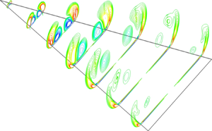
Figure 9 shows the total lift coefficient and the vorticity field (in the form of isosurfaces for  $Q$-criteria
 $ \, =3$) at a series of instants. It is shown that the total lift coefficient
 $C_{L}$ computed by the VFM method agrees well with that obtained directly from the CFD. The lift coefficient is singular at the initial moment (which is similar to that in the starting flow of a 2-D airfoil), then drops down to a first minimum point at approximately
 $\tau =1$. After a short period during which the lift increases again from
 $\tau =1$ to
 $\tau =2.6$, it begins to drop to its long-term asymptotic value with some small amplitude oscillations. The initial singularity is mainly caused by the inertia effect at
 $\tau =0$ and the roll-up of the LEVs (Graham Reference Graham1983), while the growth and the forming of stable conical structures of the LEVs are responsible for the rapid reduction and the asymptotic behaviour of the force, respectively.
Comparison of time-dependent lift coefficients generated by the VFM method and directly from the CFD and the isosurfaces of  $Q$-criteria
 $=3$ at typical instants for a delta wing flow at
 $\alpha =60^{\circ }$ and
 $Re=5\times 10^{4}$.

As we know, four regimes can be described for steady flow incident on a delta wing at AOA from  $0^{\circ }$ to
 $60^{\circ }$ (Ayoub & McLachlan Reference Ayoub and McLachlan1987). They are the regime of symmetric pair of LEVs (I), the regime of independent vortex breakdowns (vortex bursting) (II), the regime of interaction between vortex asymmetry and breakdown (III) and the regime of apex vortex (IV). From the isosurfaces for
 $Q$-criteria in figure 9, we can observe the regime of initial roll-up of the LEVs (O), as well as regimes (I), (II) and (III) during the unsteady starting process considered here. These different vortex flow regimes are closely related to the force behaviour, which will be discussed in detail in § 4.2.2.
Figure 10 shows the three components of lift coefficient contributed by streamwise, spanwise and vertical vorticity ( $\omega _{x}$,
 $\omega _{y}$ and
 $\omega _{z}$). It can be seen that the lift from
 $\omega _{x}$ is dominant and its overall trend is similar to that of the total lift. In the asymptotic state, the lift from
 $\omega _{z}$ oscillates slightly around
 $0$ and, according to the componential lift from
 $\omega _{x}$ and
 $\omega _{y}$, the vorticity direction giving main force contribution can be identified as
 $( 0.13,0.58,0)$ in the wing plane (i.e. the
 $x\text {--}y$ plane), at an angle
 $\delta \approx 12.63^{\circ }$ to the axis of the wing, which is slightly smaller than the semivertex angle of the delta wing (
 $\beta =\arctan /{4}$). Note that
 $\omega _{y}$ contains both bound vorticity in the plane of the wing and the component of LEVs in the spanwise direction.
Time-dependent lift coefficients contributed by vorticity in different directions for a delta wing flow at  $\alpha =60^{\circ }$ and
 $Re=5\times 10^{4}$.

4.2.2. The spatial distribution of vortex force contribution
A quantitative study on how much the vorticity in the flow field contributes to lift is demonstrated here. Drag can be analysed in a similar way. By normalizing equation (2.12), we have
 \begin{equation} C_{L}=\iiint_{\Omega }\left(\frac{\textrm{d}C_{L,1}}{\textrm{d}\Omega }+\frac{\textrm{d}C_{L,2}}{\textrm{d}\Omega }+ \frac{\textrm{d}C_{L,3}}{\textrm{d}\Omega }\right)\,\textrm{d}\Omega, \end{equation}
where the local lift coefficient intensity contributed by  $\omega _{x}$,
 $\omega _{y}$ and
 $\omega _{z}$ are defined as
 \begin{equation} \left. \begin{array}{c@{}}
\dfrac{\textrm{d}C_{L,1}}{\textrm{d}\Omega
}=-\dfrac{2 \boldsymbol{\Lambda}_{L,1}\cdot
(0,v,w)\omega _{x}}{V_{\infty }^{2}S},\\
\dfrac{\textrm{d}C_{L,2}}{\textrm{d}\Omega
}=-\dfrac{2\left( \boldsymbol{\Lambda}_{{L,2}} \cdot
(u,0,w)-V_{\infty }\right) \omega _{y}}{V_{\infty
}^{2}S},\\ \dfrac{\textrm{d}C_{L,3}}{\textrm{d}\Omega
}=-\dfrac{2 \boldsymbol{\Lambda}_{{L,3}}\cdot
(u,v,0)\omega _{z}}{V_{\infty }^{2}S}. \end{array}
\right\} \end{equation}
For four typical instants ( $\tau = 0.2,\ 1,\ 6.5$ and 11.5) located in the four different regimes (O, I, II, III), the spatial distribution of
 ${\textrm {d}C_{L,1}}/{\textrm {d}\Omega }$,
 ${\textrm {d}C_{L,2}}/{\textrm {d}\Omega }$ and
 ${ \textrm {d}C_{L,3}}/{\textrm {d}\Omega }$ at different cross-sections are shown in figure 11. The red contours show the positive lift contribution while the blue contours show the negative lift contribution. The lift contribution of each concentrated LEV contains both positive and negative parts. It is shown that the main region to contribute lift is consistent with the region where LEVs are located, which reflects the fact that near-body vortices are more likely to induce pressure (thus lift) variation according to the Biot–Savart law. Except for regime O, the lift due to
 $\omega _{y}$ or
 $\omega _{z}$ is much lower than that from
 $\omega _{x}$.
Contours of vortex lift coefficient distribution for a delta wing starting flow at  $\alpha =60^{\circ }$ and
 $Re=5\times 10^{4}$ for instants
 $\tau =0.2$,
 $\tau =1$,
 $\tau =2.5$ and
 $\tau =11.5$.
 $(a{,}d{,}g{,}j)$ Contours of
 $\textrm {d}C_{L,1}/\textrm {d}\Omega$ contributed by streamwise vorticity
 $\omega _{x}$.
 $(b{,}e{,}h{,}k)$ Contours of
 $\textrm {d}C_{L,2}/\textrm {d}\Omega$ contributed by spanwise vorticity
 $\omega _{y}$.
 $(c{,}f{,}i{,}l)$ Contours of
 $\textrm {d}C_{L,3}/\textrm {d}\Omega$ contributed by vertical vorticity
 $\omega _{z}$.

In regime O (e.g.  $\tau =0.2$), the LEVs’ area, thus the vortex lift contributing area expands while the total lift decreases as shown in figure 9. This is because the lift contribution is proportional to not only the circulation but also the magnitude of VFM vectors. The circulation of the LEV spreads to a larger area where the magnitude of the VFM vectors decay as
 $1/r^{3}$ (
 $r$ is the distance from the LE) according to the properties of the solution for Laplace equation.
In regime I (e.g.  $\tau =1$), the LEVs are fully developed in a near-conical area above the wing and stabilized by the axial flow effect. For the streamwise vortex, the outer part contributes positive lift, while the inner part contributes negative lift. The lift contribution from spanwise vorticity is small, and the lift contribution from vertical vorticity mainly locates above the front part of the wing.
Regime II occurs in the rear part of the wing and propagates towards the apex, which can be seen from figure 9. Figure 11 $(g)$ shows that in this regime, the negative lift contribution regions for streamwise vortex are squashed to the wing and the lift contribution regions for vertical vortex spread downstream as shown in figure 11
 $(i)$.
Regime III leads to an asymmetrical vorticity distribution, and then an asymmetrical lift distribution (figure 11j–l). It is worth noting that the main lift contribution comes from streamwise vortex and the main region for positive lift contribution lies in an approximate symmetric region at the outer edge of the concentrated LEV. The flow structure reaches a quasi-steady state since then, leading to an asymptotic value of the total lift coefficient.
4.3. Analysis of the force due to LEV
As mentioned above, the lift due to LEV is dominant, which can be represented approximately by the lift due to the streamwise vortex ( $\omega _{x}$). Here the spatial distribution of
 ${\textrm {d}C_{L,1}}/{\textrm {d}\Omega }$ contributed by
 $\omega _{x}$ is studied both for large AOA flow at different instants and for moderate AOA flow at different cross-sections.
To qualitatively analyse the contribution of vortices in the delta wing flow field to the force, Wu's (Reference Wu1981) impulse force formula
 \begin{equation} \boldsymbol{F}=-\rho \frac{\textrm{d}}{\textrm{d}t}\iint_{\Omega } \boldsymbol{x}\times \boldsymbol{\omega }\,\textrm{d}\Omega \end{equation}
is applied to the vertical 2-D flat plate flow in figure 1 $(b)$ to give the normal force formula acting on the flat plate
 \begin{equation} F_{N}=-\rho \iint_{\Omega }\left[ \boldsymbol{U}\times \boldsymbol{\omega }\right] _{N}\,\textrm{d}\Omega -\rho \iint_{\Omega } \left[ \boldsymbol{x}\times \frac{\textrm{d} \boldsymbol{\omega }}{\textrm{d}t}\right] _{N}\,\textrm{d}\Omega. \end{equation}
If  ${\textrm {d}\boldsymbol{\omega }}/{\textrm {d}t}=0$, the normal force will only be determined by the first term in (4.6). Note that, strictly,
 ${\textrm {d}\boldsymbol{\omega }}/{\textrm {d}t}\neq 0$ at any time because in the 2-D flat plate analogy the changing rate of the feeding vortex sheet is always non-zero and for the 3-D delta wing flow the wake is continuously developing and changing. Therefore there will be a contribution from
 ${\textrm {d} \boldsymbol{\omega }}/{\textrm {d}t}$ at all times, which effectively gives a contribution to the inertia force term. However, as mentioned before, in some area of the flow field for unsteady and quasi-steady flows at specific instants, the vortex structures and the vorticity inside them can be treated as fixed and unvarying, in other words,
 ${\textrm {d}\boldsymbol{\omega }}/{\textrm {d}t}$ can be treated as zero. In these areas, by simply analysing the sign of
 $- \boldsymbol{U}\times \boldsymbol{\omega }$ as shown in figure 1(b,c), and considering the analogy between
 $L$ on the delta wing and
 $F_{N}\cos \alpha$ on the flat plate, one can easily come to the conclusion that a pair of streamwise vortices contribute a positive lift when separating laterally, and lead to a negative lift when moving transversely towards each other. This qualitative conclusion will be further verified and compared with the results from our 3-D VFM methods.
4.3.1. For large AOA flow at different instants
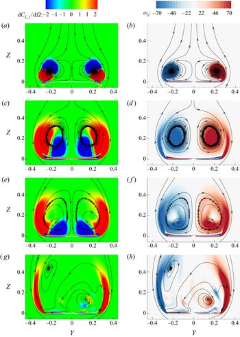
Figure 12 shows the lift coefficient distribution in the midchord cross-section ( $x=0$) normal to the delta wing at
 $\alpha =60^{\circ }$ and
 $Re=5\times 10^{4}$ at four typical instants
 $( \tau =0.2,1,2.5\text { and }11.5)$. Each instant represents a specific regime. The 2-D streamlines in the same cross-section are also shown.
Contours of vortex lift coefficient distribution  $\textrm {d}C_{L,1}/\textrm {d}\Omega$
 $(a{,}c{,}e{,}g)$ and contours of streamwise vorticity
 $\omega _{x}$
 $(b{,}d{,}f{,}h)$ at a cross-section of
 $x=0$ of a delta wing, which is starting from rest at
 $\alpha =60^{\circ }$ and
 $Re=5\times 10^{4}$, for typical instants
 $\tau =0.2$ (a,b),
 $1$ (c,d),
 $2.5$ (e,f) and
 $11.5$ (g,h).

According to the streamlines and contours of vorticity in figure 12, a pair of contra-rotating LEVs form and grow symmetrically during regime O, I, II (e.g.  $\tau =0.2$,
 $1$ and
 $2.5$). Part of the vorticity (shown as red in figure 12
 $a{,}c{,}e$) in the concentrated LEVs contributes a large positive lift and the other part (shown as blue in figure 12
 $a{,}c{,}e$) contributes a small negative lift, leading to a positive total lift. The symmetrical vortical structure breaks down in regime III (e.g.
 $\tau =11.5$) and the contours of vorticity in the vortex sheet connecting to both starboard and port LEs are much denser than in the core region of the LEVs, leading to the corresponding positive lift contributing region shown as red in figure 12
 $(g)$. This region is relatively stable in the asymptotic state of regime III since the vortex spiral doesn't grow any more and the velocity away from the axis only depends on the lateral flow effect (
 $V_{\infty }\cos \alpha \tan \beta$).
Moreover, it is not surprising to find that in regimes O and III, the vortex force distribution in figure 12(a,g) are in agreement with the qualitative conclusion apparent from (4.6), i.e. a pair of streamwise vortices contribute a positive lift when separating laterally, and lead to a negative lift when moving transversely towards each other. This is because, in these two regimes, the vorticity reduction effect is weak thus the lift contribution from  ${\textrm {d} \boldsymbol{\omega }}/{\textrm {d}t}$ is small. On the contrary, in the regimes I and II, the vorticity reduction effect is strong, thus the first term in (4.6) alone cannot represent the total vortex force contribution accurately and the quantitative results shown in figure 12(c,e) do not agree with the qualitative conclusion mentioned above.
4.3.2. For moderate AOA flow at different cross-sections
For delta wing flow at large AOA, it is surprising to find that, in the asymptotic state, the force comes mainly from the spiral vortex sheet rather than the centre core region of the LEVs. As a comparison, a common case, the quasi-steady delta wing flow at  $Re=5\times 10^{4}$ and a moderate AOA (
 $\alpha =35^{\circ }$) is studied using the VFM method proposed here. The results are shown in figure 13. Without any LEV bursting or interaction, the flow is symmetric. The left halves of figures 13(a)–13(c) show the
 $y\text {--}z$ plane contours of
 ${\textrm {d}C_{L,1}}/{\textrm {d}\Omega }$ at three different chordwise cross-sections
 $x=-0.5$ (a quarter chord),
 $0.5$ (3/4 quarter chord) and
 $0.99$ (near the TE), and the right halves show the contours of
 $\omega _{x}$. Streamlines are also drawn. It is obvious that the magnitude of the vorticity directly determines the intensity of the lift contribution. In all cross-sections, the vorticity of the LEVs are condensed in the vortex core region as well as the spiral vortex sheet region, in which the upper part with a cross-flow
 $( y\text {--}z)$ velocity towards the axis of symmetry contributes a negative lift (blue) while the lower part with a cross-flow
 $( y\text {--}z)$ velocity away from the axis of symmetry contributes quasi-steady flow field considered here, the results in figure 13 shows good agreement with the qualitative conclusion drawn from Wu's impulse force formula (4.6).
The  $y\text {--}z$ plane contours of lift coefficient intensity
 $\textrm {d}C_{L,1}/\textrm {d}\Omega$, contours of the streamwise vorticity
 $\omega _{x}$ and the streamlines at various chordwise locations for the
 $AR=1$ delta wing with
 $\alpha =35^{\circ }$,
 $Re=5\times 10^{4}$ at asymptotic flow state:
 $(a)$
 $x=-0.5$;
 $(b)$
 $x=0.5$;
 $(c)$
 $x=0.99$.

The drag coefficient can be analysed in a similar way as the lift coefficient, thus we omit the details here.
4.4. Vortex force at different AOAs and for different Reynolds numbers
Figure 14 shows good comparisons of lift and drag between theory and CFD for three AOAs  $(\alpha =60,\ 45\text { and }15^{\circ })$ at
 $Re=5\times 10^{4}$. Among these results, the lift coefficient is the largest at
 $\alpha =45^{\circ }$, while the drag coefficient increases with the increasing of AOA. Both lift and drag curves present the same trend. They drop down from singularity to a minimum value and then oscillate up and down to an asymptotic value with some small amplitude oscillations. The period of oscillation seems to be independent of the AOA while the amplitude of oscillation increases with the increasing of AOA. Good agreements are also found for the lift coefficients at
 $\alpha =45^{\circ }$ with different Reynolds numbers (
 $1\times 10^{4}$,
 $5\times 10^{4}$,
 $1\times 10^{5}$ and
 $1\times 10^{6}$), as shown in figure 15. As mentioned earlier, for the Reynolds numbers considered here, the CFD results show that the skin friction force is negligible compared with the pressure force, thus the friction force has been excluded in figures 14 and 15. The small offset between VFM and CFD predicted loads is due to the numerical methods which calculate the VFM coefficients and provide the velocity/vorticity fields.
Comparison between the theoretical and CFD results for lift and drag coefficients for delta wing flow at  $Re=50\,000$ and at different AOAs.

Comparison between theory and CFD for time-dependent lift coefficients for delta wing flow at  $\alpha =45^{\circ }$ and at different Reynolds numbers. The two components
 $L^{( 1) }$ and
 $L^{( 2) }$ are also shown as dashed lines and dash–dot lines, respectively.

The non-dimensional coefficients of the two lift components  $L^{( 1) }$ and
 $L^{( 2) }$ calculated by (2.15) are also shown in figure 15. Two domains with different sizes given in § 4.1 are used here to extract forces. The lift coefficients in figures 15
 $(a)$ and 15(b) are obtained from a larger domain and those in figures 15
 $(c)$ and 15
 $(d)$ are obtained from a smaller domain. We mention again that the feasibility on truncated domain shown here is only a preliminary study for the application of this VFM method. More feasibility studies related to the application of this method to PIV data will be conducted in future works.
It is shown in figure 15 that the first component ( $L^{( 1) }$), which is contributed from the vortices in the sampling field, follows the same trend as the total vortex lift for a long period of time, and it begins to grow slowly and monotonically over time when the total lift changes asymptotically to a constant. During a period of time after starting, the second component (
 $L^{( 2) }$) is only contributed by the vortices close to the body surface. It is slightly negative and decreases monotonically with time. When there are vortices moving out of the computation domain (
 $\tau \gtrsim 9$ in figure 15c,d),
 $L^{( 1) }$ starts to decline while
 $L^{( 2) }$, containing the lift contribution from all the missing vortices, begins to rise.
From another point of view, in unsteady flow problems, the first term is dominant while in steady or quasi-steady flows, the second term is dominant as discussed in § 2.2.3.
5. Summary
The 3-D VFM method for flow around an arbitrary wing at relatively large Reynolds numbers has been developed. As a bridge between the integral force and the evolution of local vortical structures, the 3-D VFMs together with an integral force formula are capable of performing accurate force predictions and showing the force contribution of complex flow structures. With the ability to analyse the force contribution of each given vortex without knowing the flow field, the designers can take advantage of a ‘useful’ vortex and try to minimize an ‘adverse’ vortex through flow control. Another advantage of this 3-D VFM method lies in the potential for extracting force from incomplete flow data, e.g. PIV fields.
The total force acting on the wing has been expressed either as the sum of streamwise vortex force, spanwise vortex force and vertical vortex force, or as the sum of a main term and a correction term which represents the force contribution of excluded vortices which are very close to or far from the body. The main force term is the sum of the vector products of the vortex force vector  $( \boldsymbol{\Lambda}_{{L,i}}/\boldsymbol{\Lambda}_{{D,i}},i=1,2\text { or }3)$ and the local velocity
 $(( 0,v,w) ,( u,0,w)$ or
 $( u,v,0) )$ multiplied by the local vorticity
 $(\omega _{x},\omega _{y}$ or
 $\omega _{z})$ in three coordinate planes. The VFM vectors can be easily precomputed by solving a 3-D Laplace equation and used to build VFMs.
Through the sectional VFMs study, we found that in the front part of the delta wing, the VFM for normal force in the  $y\text {--}z$ plane for streamwise vorticity
 $( \omega _{x})$ is similar to that for a 2-D flat plat, while the similarity doesn't extend to the rear part, especially the part close to the TE. This is consistent with the analogy between the lift of a slender delta wing and the normal force of a 2-D flat plate with growing width. The analogy is no longer accurate in the rear part of the wing due to the 3-D effect.
The precomputed VFMs, together with vortices obtained by CFD have been used to predict the vortex force on an impulsively started delta wing at high-AOAs. The long-time asymptotic results from CFD are compared with Polhamus’ inviscid theory as well as Earnshaw & Lawford's experimental results. The proposed VFM method performs well compared with direct CFD evaluation. It has been observed that the force curve shows some similar characteristics to that in 2-D airfoil starting flow, and the vortical structures during the unsteady starting process experience four different regimes: the initial roll-up of the LEVs (O), the regime of symmetric pair of LEVs (I), the regime of independent vortex breakdowns (II), the regime of interaction between vortex asymmetry and breakdown (III). A quantitative study on how much the individual vortex elements in the concentrated LEVs contribute to force during each regime is demonstrated. It was found that part of the LEV contributes a large positive lift and part of it contributes a small negative lift, leading to a positive total lift. Moreover, we found that the force contribution is mainly due to the conical vortex sheet rather than the central core, which differs from the moderate AOA cases where the large force contribution area lies in both the conical vortex sheet and the centre core areas.
Since the main scope of this work is the development and validation of a theoretical method, the capability of the method as the domain is decreased in size or as the sampling is made coarser or when dealing with noise in real data has not been studied in this work. Future work will consider these points with real PIV data and also extend the work to turbulent flows.
Acknowledgements
We are grateful to Professor Zi-Niu Wu for his contribution to this work. This work has received funding from the European Union's Horizon 2020 research and innovation programme under the Marie Skłodowska-Curie grant agreement no. 765579.
Declaration of interests
The authors report no conflict of interest.