
I. INTRODUCTION
Light weight magnesium alloys are of great potential to be used in the aerospace, military, biomedical devices, and automotive industries for their high specific strength, and excellent machinability.Reference Zheng, Liu, Wan, Yang and Shu1,Reference Luo2 At present, a large number of applications of magnesium alloys are casting parts, such as engine blocks, transfer cases, and wheel hubs.Reference Hono, Mendis, Sasaki and Oh-ishi3–Reference Zhu, Gibson, Nie, Easton and Abbott5 Accordingly, the development of high-strength casting magnesium alloys is of significance to promote further applications of magnesium alloys.
It was reported that the addition of rare-earth (RE) elements to magnesium alloys shows good precipitation hardening during the aging process.Reference Wang, Meng, Zhang and Tang6,Reference Jafari Nodooshan, Liu, Wu, Alizadeh, Mahmudi and Ding7 A certain amount of Zn addition can significantly improve the strengthening of the Mg-RE alloys, and different types of LPSO structures including 6H, 10H, 14H, 18R, and 24R can be easily observed in the Mg-RE-Zn series.Reference Matsuda, Li and Kawamura8–Reference Nishida, Kawamura and Yamamuro10 Kawamura et al.Reference Kawamura, Hayashi, Inoue and Masumoto11 developed a Mg97Zn1Y2 (at.%) alloy, which exhibited the tensile yield strength (YS) of about 610 MPa and elongation to failure of 5% at RT, by rapidly solidified powder metallurgy. Xu et al.Reference Xu, Zheng, Xu, Wu, Wang, Kamado, Wang and Lv12 fabricated a high-strength Mg–8.2Gd–3.8Y–1.0Zn–0.4Zr (wt%) alloy with an ultimate tensile strength (UTS) of 517 MPa, YS of 426 MPa, and elongation to failure of 4.5%. Zheng et al.Reference Zheng, Liu and Wang13 reported that the UTS and elongation of Mg–10Gd–6Y–2Zn–0.6Zr (wt%) alloy were 432 MPa and 5% by extrusion and aging treatment. Proper controlling of the morphology, size, volume fraction, and distribution of the strengthening phase is important to optimize mechanical properties of the alloys; alloying is a relatively simple and effective method.
Current research about Mg–Gd–Y–Zn–Zr alloys mainly focuses on extrusion alloys, while cast alloys are more widely used. How to obtain high strength and ductility simultaneously in a cast magnesium alloy is an important question. In the present work, the evolution of the microstructure and mechanical properties of the Mg–Gd–Y–Zn–Zr alloys from the as-cast to the solution-treated and aging-treated conditions were systematically investigated.
II. EXPERIMENTAL PROCEDURES
Alloys of actual composition Mg–10.10Gd–2.98Y–0.53Zn–0.61Zr, Mg–10.05Gd–3.05Y–0.98Zn–0.59Zr, and Mg–10.06Gd–2.98Y–1.58Zn–0.61Zr (wt%, are identified as A, B, and C, respectively) were prepared from high purity (≥99.9%) Mg, Zn, and Mg–30Y, Mg–30Gd, and Mg–30Zr (wt%) master alloys by induction melting in a mild steel crucible at approximate 1053 K under a protective Ar atmosphere. The melt was cooled in water after adequate stirring. The as-cast ingots were solution-treated at 793 K for 8 h followed by an immediate water quenching. Artificial aging process was carried out at 493 K to investigate the age hardening behaviors with different times.
The microstructures of the specimens were analyzed using optical microscopy (OM; DM2500M, Leica Microsystems, Wetzlar, Germany), scanning electron microscopy (SEM; SU5000, Hitachi, Tokyo, Japan), and energy dispersive spectroscopy (EDS). Phase analysis was conducted using a Rigaku D/MAX2500PC X-ray diffractometer (Rigaku, Tokyo, Japan) with a copper target at scanning angles from 20° to 90° and a scanning speed of 5°/min. The detailed microstructure of the samples was further analyzed using a TEM (JEM-2100F, JEOL Ltd., Tokyo, Japan) operated at an accelerating voltage of 200 kV. Vickers hardness testing was taken using 1.96N load and a holding time of 15 s, where at least 8 points were measured for each sample. Tensile testing at ambient temperatures was performed on a Zwick/Roell Z020 tensile testing machine (Zwick Roell, Ulm, Germany) at a stretching rate of 1.5 mm/min. An average of three measurements was used. The fracture surfaces were analyzed by SEM.
III. RESULTS
A. Microstructures of the as-cast and solution-treated alloys
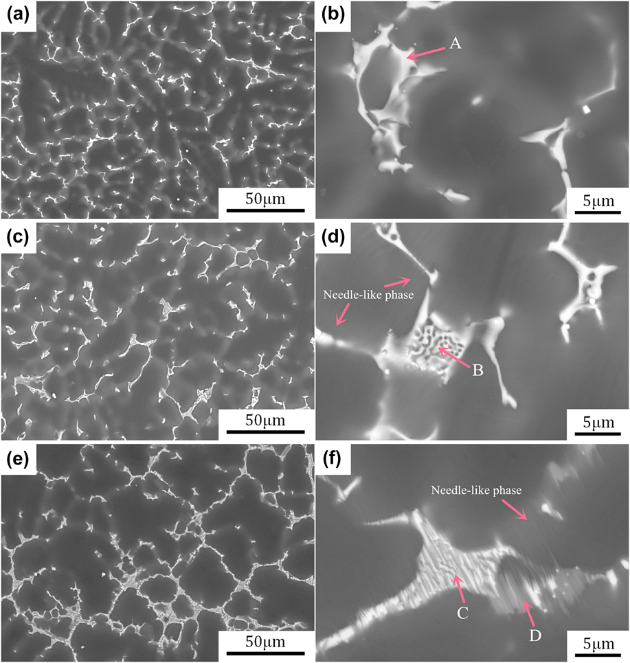
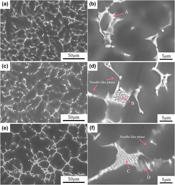
Figure 1 shows the SEM images of the as-cast Mg–Gd–Y–Zn–Zr alloys. The as-cast alloys mainly contain bright second phases distributing along the grain boundaries discontinuously, and the average grain sizes of the alloys A, B, and C are 39.5 ± 1.3, 37.2 ± 0.8, and 34.6 ± 1.1 μm, respectively. The eutectic phase become coarse and continuous with the increase of Zn content, as shown in Figs. 1(a), 1(c), and 1(e). In the alloy A, the eutectic phases are distributed at grain boundaries in the form of island-shaped. While in the alloys B and C, most of the eutectic phases are mainly distributed along the grain boundaries with a hollow-out skeleton morphology. In addition, some needle-like phases can be observed near the grain boundaries in the alloys B and C [Figs. 1(d) and 1(f)]. Moreover, in the alloy C, some gray lamellar phases are observed adjacent to the hollow-out skeleton phases, as shown in Fig. 1(f).
SEM images of the as-cast Mg–Gd–Y–Zn–Zr alloys: (a and b) alloy A, (c and d) alloy B and (e and f) alloy C.

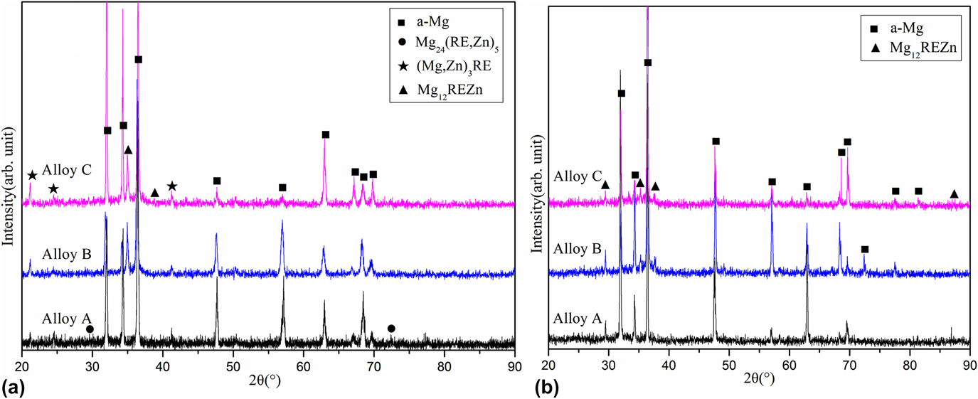
Figure 2(a) shows the XRD patterns of the as-cast Mg–Gd–Y–Zn–Zr alloys. This indicates that the microstructure of the as-cast alloy A mainly consists of α-Mg, Mg24(RE,Zn)5 and (Mg,Zn)3RE phases. While in the as-cast alloys B and C, the Mg24(RE,Zn)5 phase disappeared, and the main second phases are (Mg,Zn)3RE and Mg12REZn (LPSO) phases.
XRD patterns of the Mg–Gd–Y–Zn–Zr alloys in the (a) as-cast and (b) solution-treated conditions.

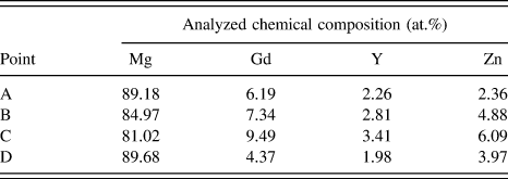
Table I summarizes the chemical compositions of the selected points in Figs. 1(b), 1(d), and 1(f), as detected by EDS. Combined with the XRD results, the island-shaped second phases (point A) in the alloy A are mainly composed of Mg24(RE,Zn)5, with a small amount of Zn content. While the bright hollow-out skeleton phases (point B and C) in the alloys B and C are mainly composed of the (Mg,Zn)3RE phase. The gray lamellar phases (point D), which are observed in the alloy C with a RE/Zn ratio of nearly 1, mainly consist of Mg12REZn phase.
EDS elemental analysis of the phase in as-cast alloys marked A, B, C, and D in Fig. 1.

Figure 3(a) shows the bright-field TEM images and the corresponding SAED pattern of needle-like phases in the as-cast alloy B. The needle-like phases with a width of several nanometers are parallel to each other. The 2H–Mg crystal structure is recognized from the corresponding diffraction pattern and the light streaks appeared between diffraction spots of (0001)α and (0002)α demonstrate that these line contrasts are stacking faults on (0001)α basal planes, which are similar to reports.Reference Suzuki, Kimura, Koike and Maruyama14,Reference Suzuki, Kimura, Koike and Maruyama15 It is obvious that these needle-like phases are not LPSO phases but stacking faults. Figure 3(b) shows the bright-field TEM images and the corresponding SAED pattern of the gray lamellar phases in the as-cast alloy C. It is obvious that five extra diffraction spots occur at the intervals between (0000)18R and (00018)18R spots, which suggested that the gray lamellar phases are 18R-LPSO phases.Reference Liu, Bai, Yan, Yan, Ma and Jiang16,Reference Zhu, Morton and Nie17
Bright-field TEM image and corresponding SAED pattern  $\left( {{\rm{B//}}{{\left[ {{\rm{11\overline{2}0}}} \right]}_\alpha }} \right)$ of the needle-like phase (a) in the alloy B and gray lamellar phase (b) in the alloy C.

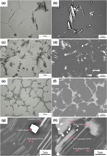
Figure 4 shows the optical and SEM images of the solution-treated Mg–Gd–Y–Zn–Zr alloys. It could be observed that the three alloys contain gray bulk phase, lamellar phase, and cuboid phase, which are mainly distributing along the grain boundaries. Compared with the as-cast alloys, the grain size of the alloys increases obviously, especially the alloy A. Combined with XRD patterns of the solution-treated Mg–Gd–Y–Zn–Zr alloys given in Fig. 2(b), exhibited peaks corresponding to only α-Mg and Mg12REZn (LPSO phase), without any other eutectic phase. It is indicated that the gray bulk phase and lamellar phase are LPSO phases, which is consistent with reports.Reference Huang, Wang, Hou, Huang and Pan18 The volume fraction of LPSO phases is 3.4%, 16.5%, and 22.7%, respectively, as detected by Image Pro Plus software. The lamellar LPSO phases possess different orientations in different grains and grow parallel with one another from the grain boundaries to the grain interior, as shown in Figs. 4(d) and 4(f), which suggests that the lamellar LPSO phases have specific orientation relationship with the α-Mg matrix crystals. As shown in Fig. 4(g), the cuboid phase hinders the extension of the rod-shaped 14H-LPSO, causes it coarser, and forms into lamellar LPSO. The lamellar phase is smooth and fine, while the bulk phase is thicker, as shown in Fig. 4(h).
Optical and SEM images of the solution-treated Mg–Gd–Y–Zn–Zr alloys: (a and b) alloy A, (c and d) alloy B and (e and f) alloy C; high-resolution SEM image of (g) alloy B and (h) alloy C.

Figure 5(a) shows a bright-field TEM image and corresponding diffraction patterns of the cuboid phase in the solution-treated alloy C. The cuboid phase has a regular shape, with a size of about 0.6–3 μm, which are mainly distributed at the grain boundaries. It is a face-centered cubic (fcc) crystal structure with a = 0.56 nm and the composition is identified to be RE-rich compound with Mg–33.66Gd–23.95Y–1.62Zn (wt%) by EDS. Suitable quantities of cuboid-shaped phases can improve the strength of the alloy, but excessive amounts will lead to the stress concentration near the grain boundary and reduce the mechanical properties.Reference Li, Wu, Chen, Nodooshan, Liu, Wang and Ding19,Reference Chen, Shu, Zhao, Zhao, Wang and Yuan20
Bright-field TEM image and corresponding SAED pattern of the (a) cuboid phase (B//[001]α) in the solution-treated alloy C and (b) LPSO phase  $\left( {{\rm{B//}}{{\left[ {{\rm{11\overline{2}0}}} \right]}_\alpha }} \right)$ in the solution-treated alloy B.

Figure 5(b) shows the bright-field TEM image and the corresponding SAED pattern of the LPSO phase in the solution-treated alloy B. The periodic diffraction spots of the 14H-LPSO phase appear at positions of n/14 (where n is an integer) of (0002)α-Mg fundamental diffraction. It is suggested that the Mg24(RE,Zn)5, (Mg,Zn)3RE, stacking faults, and 18R-LPSO phases were completely transformed into the 14H-LPSO phases during solution treatment, which is consistent to reports.Reference Cheng, Zhao, Lu, Hou, Bu and Yan21–Reference Xu, Zheng, Wu, Wang, Fan, Xu, Kamado, Liu, Wang and Lv23
B. Aging hardening behaviors of solution-treated alloys and microstructures of peak-aged alloys
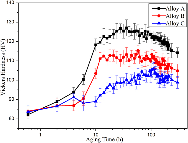
Figure 6 shows the age hardening behaviors of the solution-treated Mg–Gd–Y–Zn–Zr alloys at 220 °C, and the standard deviation is given in parenthesis following the value of peak hardness. The alloy A exhibits the best aging hardening response, the hardness of which increases obviously in 0–20 h and then reached a peak hardness of 127.56(4.72)HV after 36 h. The peak hardness of the solution-treated alloy B is obtained after 58 h, with a value of 115.47(2.87)HV. However, the solution-treated alloy C exhibits relatively poor age hardening behaviors, the peak hardness is obtained after 113 h, with a value of 105.91(3.26)HV. The formation of the 14H-LPSO phase results in a decrement of the RE content in the α-Mg matrix, which leads to the aging hardening response of the Mg–Gd–Y–Zn–Zr alloys that are significantly smaller.
Age hardening behaviors of the solution-treated Mg–Gd–Y–Zn–Zr alloys during aging at 220 °C.

Figure 7 shows the bright-field TEM image and corresponding SAED pattern of the peak-aged Mg–Gd–Y–Zn–Zr alloys. A large number of ellipsoidal shaped precipitates can be observed in the matrix of peak-aged alloy A, as shown in Fig. 7(a). The SAED pattern of the  ${\left[ {2\overline 1 \overline 1 0} \right]_\alpha }$ zone axis shows that the extra diffraction spots located at
 $1{\rm{/}}4{\left( {\bar{1}0\bar{1}0} \right)_\alpha }$,
 $1{\rm{/}}2{\left( {\bar{1}0\bar{1}0} \right)_\alpha }$, and
 $3{\rm{/}}4{\left( {\bar{1}0\bar{1}0} \right)_\alpha }$. Such a diffraction feature indicated that the ellipsoidal shaped precipitates are β′ phases with a bco structure. These precipitates exhibit a semicoherent structure with α-Mg, which can effectively inhibit the slipping of the base plane. The bright-field TEM image and corresponding SAED pattern
 $\left( {{\rm{B//}}{{\left[ {{\rm{11\bar{2}0}}} \right]}_\alpha }} \right)$ of the peak-aged alloy C are shown in Fig. 7(b). It is observed that a small amount of β′ phases extend perpendicularly to the 14H-LPSO phase. The average sizes of β′ phases in peak-aged alloy A are about 12 nm in thickness and 64 nm in diameter. However, the average sizes of these particles in peak-aged alloy C are obviously bigger than that in peak-aged alloy A, with a thickness of 37 nm and a diameter of 184 nm. It is suggested that the precipitation of the β′ phase decreases with increasing Zn content, and the average size of this phase is significantly increased. There is a competitive demand for RE atoms between the formation of the 14H-LPSO phase and the β′ precipitates.
Bright-field TEM image and corresponding SAED pattern of (a) β′ precipitates  $\left( {{\rm{B//}}{{\left[ {{\rm{2\overline{1}\,\overline{1}0}}} \right]}_\alpha }} \right)$ in peak-aged alloy A and (b) LPSO phase accompanied by β′ precipitates
 $\left( {{\rm{B//}}{{\left[ {{\rm{11\overline{2}0}}} \right]}_\alpha }} \right)$ in peak-aged alloy C.

C. Mechanical properties
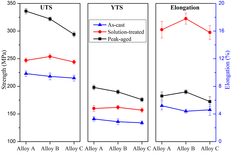
Figure 8 shows the typical mechanical properties of the Mg–Gd–Y–Zn–Zr alloys under different conditions. This indicates that the mechanical properties of alloy B are better than that of other two alloys in the as-cast condition, and the values of the UTS, YTS, and elongation are 223 MPa, 141 MPa, and 5.2%, respectively. Due to the solid solution strengthening and 14H-LPSO phase strengthening, the mechanical properties of these alloys are improved after solution treatment, especially elongation. The solution-treated alloy B shows the optimal mechanical properties, and the values of UTS and YTS are about 254 MPa and 162 MPa, respectively, with a good elongation of 17.8%. The mechanical properties of the three alloys are greatly improved after peak aging treatment except elongation. The peak-aged alloy A exhibits the optimal mechanical properties, and the UTS, YTS, and elongation are 336 MPa, 198 MPa, and 6.6%, respectively. Compared with the as-cast alloy A, the UTS is improved by 113 MPa, and the increment of YTS is 57 MPa. Both UTS and YTS of peak-aged alloy B are improved significantly, with the values of 322 and 190 MPa, respectively. However, the alloy C with high Zn content have less age hardening response, and the values of the UTS, YTS, and elongation are 294 MPa, 176 MPa, and 5.8%, respectively.
Tensile properties of the Mg–Gd–Y–Zn–Zr alloys under as-cast, solution-treated, and peak-aged conditions.

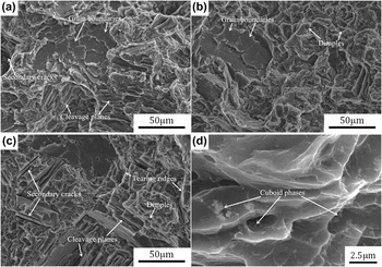
Figure 9 shows the SEM images of the fracture surfaces of peak-aged alloys A, B, and C. The fracture surfaces of peak-aged alloys A and C show large cleavage planes, grain boundaries, and secondary cracks, exhibiting typical brittle fracture. A number of plastic dimples and grain boundaries are observed in the fracture surfaces of peak-aged alloy B, which denoted that it have relatively good ductility and in accordance with the tensile results. Moreover, careful examination of the tensile fracture surface of the peak-aged alloy A is shown in Fig. 9(d), and some cuboid phases are observed in the fracture surfaces. This suggests that the cuboid phases are sensitive to the stress concentration and fractured during the tensile deformation.
SEM images of the tensile fracture surface of peak-aged alloys: (a) alloy A, (b) alloy B, (c) alloy C, and (d) enlarged magnification of the fracture surface of peak-aged alloy A.

IV. DISCUSSION
It is noted that the as-cast alloy A consists of two eutectic phases (Mg,Zn)3RE and Mg24(RE,Zn)5. Li et al.Reference Li, Zhang, Du, Li, Li, Ma, Shi, Yuan, Li and Liu24 reported that the formation temperature of Mg24(RE,Zn)5 phase is higher than that of (Mg,Zn)3RE phase, and the Mg24(RE,Zn)5 phase may be transformed from (Mg,Zn)3RE during further cooling. While in the as-cast alloys B and C, the Mg24(RE,Zn)5 phase disappears, a large number of (Mg,Zn)3RE and some needle-like stacking faults distributed along the grain boundaries. It has been reported that the addition of Zn to the Mg–Y binary alloys decreases the stacking fault energy and leads to the planar defects spreading on the basal plane of the Mg matrix.Reference Suzuki, Kimura, Koike and Maruyama14 This suggested that the needle-like stacking faults in the present as-cast alloys are formed by simultaneous addition of RE and Zn elements. In addition, 1.5 wt% Zn content leads to the formation of gray lamellar 18R-LPSO phases as well as stacking faults. The difference in atomic size between Mg (0.16 nm), Zn (0.13 nm), and RE (Gd, Y both 0.18 nm) is large, and cosegregation of RE and Zn would cancel the strain fields on the basal plane, which may work as a driving force for the formation of the LPSO structures.Reference Cheng, Zhao, Lu, Hou, Bu and Yan21,Reference Honma, Ohkubo, Kamado and Hono25 As has been proposed, the formation of LPSO phases involves not only stacking sequence ordered but also chemical composition ordered, which requires the existence of stacking faults and diffusion of solute atoms.Reference Abe, Kawamura, Hayashi and Inoue26 Therefore, the gray lamellar 18R-LPSO phases are preferentially generated in the regions where enriched with stacking faults and solute atoms, as shown in Figs. 1(e) and 1(f).
The 14H-LPSO phases always exhibit bulk or lamellar shape, and their growth involves different forms during the process of solution treatment. Some studies reported that the 14H-LPSO is generated from supersaturated α-Mg phases through the precipitation mechanism or spinodal decomposition mechanism.Reference Wu, Lin, Zeng, Peng and Ding27–Reference Zhang, Wang, Du, Liu and Li29 The RE and Zn atoms diffuse from the Mg24(RE,Zn)5 and (Mg,Zn)3RE compounds to the α-Mg matrix with the process of solution treatment. Once the condition of chemical composition and structure ordered was achieved in some areas, the 14H-LPSO phase begins to form. This is the reason why a large number of thick bulk 14H-LPSO phases are distributed in grain boundaries and a small amount of smooth fine lamellar 14H-LPSO phases growing from the grain boundaries to the grain interior, as shown in Fig. 4(h). Wang et al.Reference Wang, Song, Huang and Pan30 reported that the morphologies of two 14H-LPSO phases are changing dynamically under different solution-treated conditions, and the lamellar 14H-LPSO phase precipitates in the grain interior when the solution treatment temperature is above 350 °C. Due to the low concentrations of RE and Zn in the center of α-Mg, the growth of precipitated 14H-LPSO phases is slowed and hence the 14H-LPSO exhibits rod shape. Meanwhile, the cuboid phase is formed from the concentrations of RE, which hinders the extension of the rod-shaped 14H-LPSO, as shown in Fig. 4(g). The parallel rod-shaped 14H-LPSO is inclined to be contacted and combined into a lamellar 14H-LPSO. Therefore, there are many rod-shaped or lamellar 14H-LPSO distributed in the center of the grain in the solution-treated alloy B. In addition, the density and volume fraction of the bulk 14H-LPSO phase in the alloy C are larger than that in the alloy B, which is in accordance with reportsReference Zhu, Morton and Nie17,Reference Saal and Wolverton31,Reference Iikubo, Matsuda and Ohtani32 that some stable 14H-LPSO phases could be directly transformed from metastable 18R-LPSO phases. Zhu et al.Reference Zhu, Morton and Nie33 reported that the direct transformation from 18R-LPSO to 14H-LPSO via the gliding of two Shockley partial dislocations. As a consequence, the formation of bulk 14H-LPSO phases is mainly based on the spinodal decomposition mechanism, and the formation of lamellar 14H-LPSO phases is mainly by the precipitation mechanism.
The hollow-out skeleton (Mg,Zn)3RE phase has hard and fragile characteristics, and the (Mg,Zn)3RE/α-Mg interfaces are not coherent.Reference Wang, Song, Gao, Huang, Shi and Pan34,Reference Xu, Liu, Xu and Han35 The hard and fragile phase with a finer shape can improve the strength, but the severe coarsened net-shaped phases are more sensitive to the stress concentration.Reference Xu, Tang, Liu, Xu and Han36 Accordingly, the as-cast alloys B and C have relatively low mechanical properties. The formation of the 14H-LPSO phases minimizes the total energy in the systems and promotes the dislocation movement on the basal planes, which can effectively increase the elongation of the alloys.Reference Honma, Ohkubo, Kamado and Hono25 In addition, the 14H-LPSO phase has higher elastic moduli and Vickers hardness, which can significantly improve the tensile strength of the solution-treated alloys.Reference Chino, Mabuchi, Hagiwara, Iwasaki, Yamamoto and Tsubakino9,Reference Wang, Song, Huang and Pan30,Reference Shao, Yang and Ma37 The lamellar 14H-LPSO phases have a significantly smaller average size than the bulk 14H-LPSO phases, which can improve the mechanical properties more effectively.Reference Wang, Song, Huang and Pan30 Therefore, the alloy B exhibits the optimal mechanical properties in the solution-treated condition.
The ellipsoidal shaped β′ phases with lattice parameters a = 0.64 nm, b = 2.22 nm, and c = 0.52 nm, exhibit a semicoherent structure with α-Mg, precipitated in the peak-aged Mg–RE–Zn–Zr alloys, which can effectively inhibit the slipping of the base plane results in precipitation hardening, and significantly improving the tensile strength.Reference Han, Xu and Shan38 The formation of 14H-LPSO phases results in a decrement of the RE contents in the α-Mg matrix, which leads to the precipitation of the decrease of β′ phases with the increase of Zn contents. These precipitates can reduce the spacing between the particles and effectively enhance the dispersion strengthening. However, the β′ precipitates coherent with the matrix, which may produce a precipitate shearing mechanism, lead to an inhomogeneous distribution of slip and reduce the elongation.Reference Sundararaman, Mukhopadhyay and Banerjee39 It is suggested that the β′ phase plays a significant role in enhancing the strength, but it leads to poor ductility.
V. CONCLUSIONS
The microstructure evolution and mechanical properties of Mg–10Gd–3Y–xZn–0.6Zr (x = 0.5, 1, and 1.5 wt%) alloys in the as-cast, solution-treated, and peak-aged conditions have been investigated systematically. The obtained conclusions are summarized as follows.
(1) The microstructure observation shows that the as-cast Mg–10Gd–3Y–0.5Zn–0.6Zr alloy consists of α-Mg, (Mg,Zn)3RE and Mg24(RE,Zn)5 phases, while the Mg–10Gd-3Y–1Zn–0.6Zr and Mg–10Gd–3Y–1.5Zn–0.6Zr alloys consist of α-Mg, (Mg,Zn)3RE and some needle-like stacking faults. Moreover, some gray lamellar 18R-LPSO phases are observed in the as-cast Mg–10Gd–3Y–1.5Zn–0.6Zr alloy. This indicates that the formation of LPSO phases involves not only stacking sequence ordered but also chemical composition ordered.
(2) After solution treatment, the Mg24(RE,Zn)5, (Mg,Zn)3RE, stacking faults, and 18R-LPSO phases are completely transformed into the high temperature stable 14H-LPSO phases. The microstructure observation reveals that the formation of bulk 14H-LPSO phases is mainly based on the spinodal decomposition mechanism, and the formation of lamellar 14H-LPSO phases is mainly by the precipitation mechanism. The formation of the 14H-LPSO phases minimizes the total energy in the systems, leading to active movement of dislocations on the basal planes, and effectively increases the elongation of the alloys. The solution-treated Mg–10Gd–3Y–1Zn–0.6Zr alloy exhibits the best ductility with an elongation of 17.8%.
(3) Based on microstructure observations, the precipitation of the β′ phases decreases with increasing Zn content, and the average size of this phase is significantly increased. The precipitation of the β′ phases in the peak-aged alloys can effectively inhibit the slipping of the base plane results in precipitation hardening, significantly improving the strength, but it leads to poor ductility due to the precipitate shearing mechanism. Tensile tests indicate that the peak-aged Mg–10Gd–3Y–0.5Zn–0.6Zr alloy with most volume fraction of β′ phases exhibits the best tensile strength, and the UTS and YTS are 336 MPa and 198 MPa, respectively.
ACKNOWLEDGMENTS
This work is supported by the National Natural Science Foundation of China (Nos. 51774254, 51774253, 51701187, U1610123, 51674226, 51574207, and 51574206), The Science and Technology Major Project of Shanxi Province (No. MC2016-06), and Shanxi Province Science Foundation for Youths (No. 201601D021062).