
I. INTRODUCTION
Heat exchangers and tubes in steam generators are often made of ferritic steel 16Mo3. Mechanical loading is caused by the internal pressure within the system, which is superimposed to elevated temperatures. Reference Huttunen-Saarivirta, Antonov, Veinthal, Tuiremo, Mkel and Siitonen1 Within the heat exchanger tubes there is an aggressive environment with fluidized sand and ash particles which leads to corrosive and erosive conditions. Reference Huttunen-Saarivirta, Antonov, Veinthal, Tuiremo, Mkel and Siitonen1–Reference Rozmus-Górnikowska, Cieniek, Blicharski and Kusiński4 Besides the corrosive and erosive degradation of the material, the mechanical loadings as well as the thermal stress due to the turn-on and turn-off operations cause isothermal and thermo-mechanical fatigue (TMF) failure. Reference Bulatovic, Aleksic and Milovic5–Reference Ergün, Aydinol, Öztürk and Doruk8 The fatigue loading at elevated temperature and the corrosive environment are superimposed yielding to the final failure of components. Reference Ciofu, Nioaţă, Mihuţ and Rădulescu2 Therefore, for the protection of the ferritic steel 16Mo3, often a coating is applied which improves the resistance against the corrosive and erosive degradation. As coating material of the steel substrate, the nickel-base superalloy IN625 is particularly common. Reference Rozmus-Górnikowska, Blicharski, Kusińsk, Kuslnski and Marszyck3,Reference Rozmus-Górnikowska, Cieniek, Blicharski and Kusiński4 For this coating material, the phase diagram as well as the stability under corrosive atmosphere were simulated by thermodynamic calculations. Reference Kriegel, Fabrichnaya, Seifert, Eisenblätter, Starke and Zanler9
Knowledge on the fatigue behavior of the coated steel at elevated temperatures is necessary to realize an optimum construction of the component in the design process. Due to the internal pressure within the tubes, a biaxial-planar stress state is present. Therefore, biaxial-planar fatigue tests are helpful to overcome the gap between the real loading of the component and the uniaxial loading, which is usually applied to obtain experimental data necessary within the design process. Reference Bulatovic, Aleksic and Milovic5–Reference Psyllaki, Pantazopoulos and Lefakis7,Reference Lawton10 The usual approach uses the uniaxial material properties in the design process, and the real multiaxial stress state is transferred by the distortion energy hypothesis according to von Mises into an equivalent uniaxial stress state. Some multiaxial loading cases are critical for the safety margins if the distortion energy hypothesis is used and, thus, the biaxial fatigue tests can reduce the uncertainties of the design process. Reference Lawton10,Reference Mayer, Stark and Ambrose11
A biaxial stress state can be realized in fatigue testing by two test principles, i.e., the tension–torsion test rigs with tubular specimen geometries and the biaxial-planar tension-compression test rigs with cruciform specimens. Biaxial-planar testing is in some cases in advantage compared to the tension–torsion testing because internal and external pressure is required in the case of hollow tubular specimens Reference Ellyin and Wolodko12–Reference Bonnand, Chaboche, Gomez, Kanouté and Pacou15 to realize the real stress state of heat exchangers and steam generators.
Compound specimens with coatings on a substrate material were often investigated in different combinations due to their unique mechanical and chemical properties. The coating material IN625 was investigated in the literature under different corrosive atmospheres. Reference Zhang, Harris and McCartney16–Reference Ahmed, Bakare, McCartney and Voisey20 Since for a high-velocity oxy-fuel (HVOF) coating the mechanical interlocking to the substrate is the most important bonding contribution, the bonding strength was characterized experimentally by Boudi et al. Reference Boudi, Hashmi and Yilbas17,Reference Boudi, Hashmi and Yilbas21 Futhermore, the low-cycle fatigue loading of a IN625 coated, welded steel specimen was studied by Fadhli et al. Reference Al-Fadhli, Stokes, Hashmi and Yilbas18 at RT and under different NaCl-containing corrosion conditions. Further investigations on the Low Cycle Fatigue (LCF) behavior of compounds with a HVOF coating on a substrate material at different temperatures are given in the literature. Reference Bonora, Voorwald, Cioffi, Junior and Santos22–Reference Souza, Voorwald and Cioffi27 Because of the inhomogeneities (pores and particles) within the coating and interface and the different material behavior (ductile and brittle) or strength class between the substrate and the coating, in general, an early fatigue crack initiation and a reduced fatigue life in comparison to the uncoated material were observed. Especially, the thermal and TMF behavior of specimens with coatings of, e.g., MCrAlY or thermal barrier coatings was mainly investigated on nickel-base superalloy substrate materials. It was found that thermal and TMF loading lead to significant damage and sometimes to a reduction in fatigue life. Reference Kowalewski and Mughrabi28–Reference Okazaki40 In particular, the thermo-mechanical out-of-phase loading results in a reduced fatigue life. Reference Chen, Wang and Zhu32,Reference Huang, Wang, Zhu, Yuan and Wang39,Reference Okazaki40
However, according to this literature survey, a ferritic steel substrate material with a HVOF coating was not investigated under high-temperature LCF for different stress states. Furthermore, no studies on TMF of a ferritic steel substrate material with a HVOF coating were found.
Thus, in this study the substrate material 16Mo3 with a modified nickel-base superalloy IN625mod coating deposited by HVOF spraying is investigated under uniaxial and biaxial isothermal fatigue at 200 and 500 °C. As reference to the compound material, bulk, HVOF-sprayed specimens of the coating material were also investigated under uniaxial isothermal fatigue. The fatigue behavior of the substrate material 16Mo3 was already reported in the recent work. Reference Hoffmann and Biermann41,Reference Kulawinski, Hoffmann, Lippmann, Lamprecht, Henkel and Biermann42 Besides uniaxial isothermal fatigue tests, TMF tests with in-phase (IP) and out-of-phase (OP) loading were carried out. In particular, crack initiation and crack growth of the compound specimens were studied.
II. MATERIAL
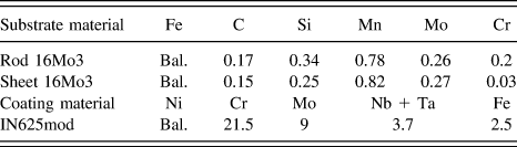
The investigated material consists of a substrate which is the heat-resistant ferritic steel 16Mo3 and as coating material a modified nickel-base superalloy IN625mod. For the uniaxial tests, a rod material with a diameter of 18 mm and a length of 3 m of 16Mo3 and for the biaxial-planar tests, a sheet material with a width of 400 mm, length 400 mm, and thickness of 20 mm of 16Mo3 were used. Both substrate materials were coated by HVOF technique with a thin layer of 200 µm of IN625mod. The chemical compositions of the materials are given in Table I.
Chemical composition in wt% of the ferritic steel 16Mo3 (substrate material) for both production routes and of the nickel-base superalloy coating material IN625mod measured by Glow Discharge Optical Emission Spectroscopy (GDOES).

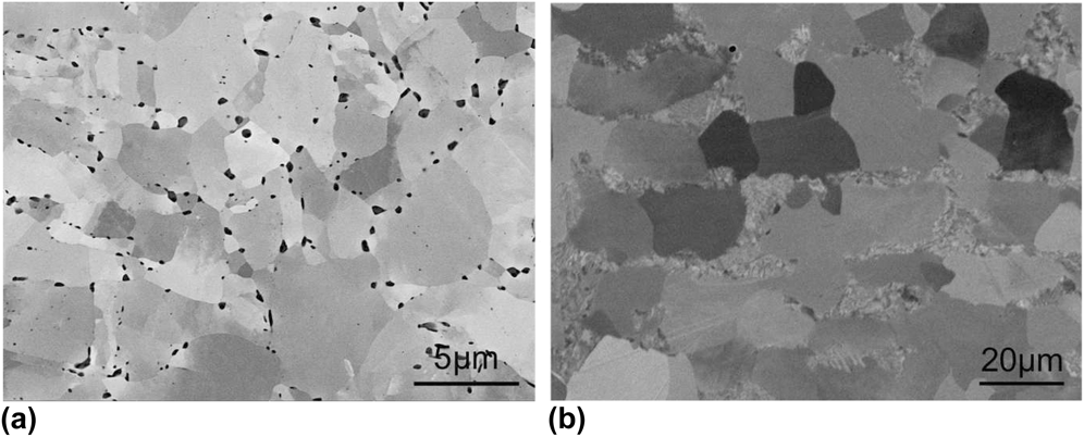
Besides the differences in chemical composition of the rod and sheet substrate materials, the microstructures were also different from each other, as reported in the recent work Reference Kulawinski, Hoffmann, Lippmann, Lamprecht, Henkel and Biermann42 and shown in Figs. 1(a) and 1(b), respectively.
Scanning electron microscopy (SEM) image in back-scattered electron contrast of the microstructure of 16Mo3 for both production routes. (a) Rod material with fine ferrite grains and carbides at the grain boundaries (section perpendicular to the rod axis). (b) Sheet material with coarser ferrite grains and line-like arrangement of the perlite, thus a rolling direction is present (section parallel to the rolling direction of the sheet material).

Figure 1(a) shows the ferritic matrix of the rod material without any fraction of perlite. The grain size had an average diameter of 2.8 µm. Carbides of molybdenum and manganese were present at the grain boundaries. In rare cases, oxides were observed within the microstructure. In contrast, the microstructure of the hot-rolled sheet material consisted of a mainly ferritic matrix with a small amount of perlite, see Fig. 1(b). Carbides were present only at few grain boundaries. The material exhibited a larger average grain size of about 15 µm. Furthermore, an alignment of perlite was present along the rolling direction. Due to the nearly globular ferrite grains, a negligibly small texture was present in the sheet material.
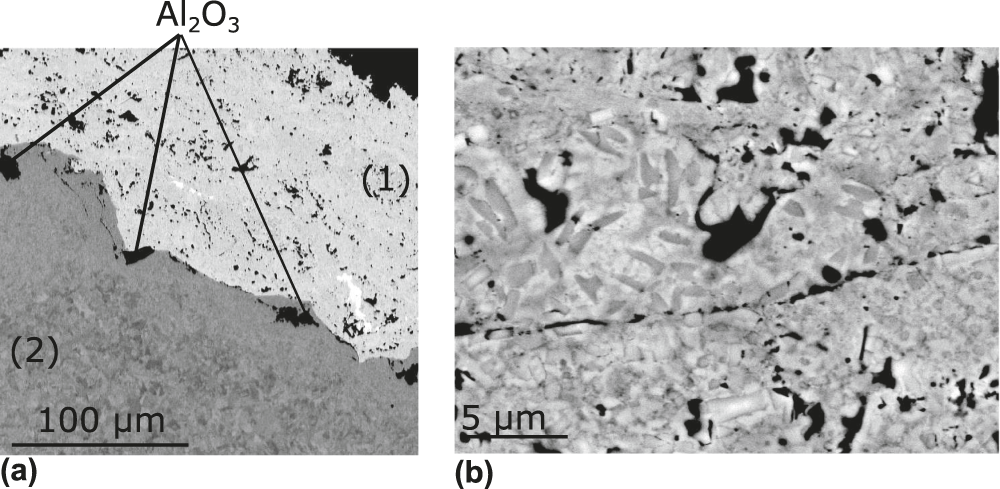
Since HVOF coatings adhere to the substrate materials by mechanical interlocking, the surfaces of the steel specimens were roughened by sandblasting before the coating process. For such a condition, the interface strength was reported by Boudi et al. Reference Boudi, Hashmi and Yilbas17 to be in the range of 45–60 MPa. Furthermore, Boudi et al. described that oxidation of the spray particles cannot be avoided during the process of HVOF. The studied coating is shown in Fig. 2. It is fine grained with a small amount of pores in the range of 1.5–4.5%. The black areas visible in Fig. 2 within the coating and at the interface can be attributed to pores and to oxide particles. The dark particles at the interface are alumina, which are residues of the sandblasting process. Furthermore, due to the sandblasting process, the near-surface region of the steel substrate was deformed. Bulk specimens of HVOF-sprayed IN625mod were produced by repeated spraying onto a flat steel substrate. Figure S1 shows the applied coating on the U-shaped steel profile. By this procedure, IN625mod was sprayed with a final thickness of 15 mm. In the previous work, the coating material was characterized at elevated temperatures under uniaxial and multiaxial static loading by small punch tests. Reference Soltysiak, Selent, Roth, Abendroth, Hoffmann, Biermann and Kuna43,Reference Selent, Soltysiak, Roth, Abendroth, Hoffmann and Kuna44
SEM image in back-scattered electron contrast of the microstructure of (a) composite material with a IN625mod coating (1) on the substrate material 16Mo3 (2) and (b) a higher magnification of the IN625mod coating.

III. EXPERIMENTAL DETAILS
A. Specimen preparation and microscopy
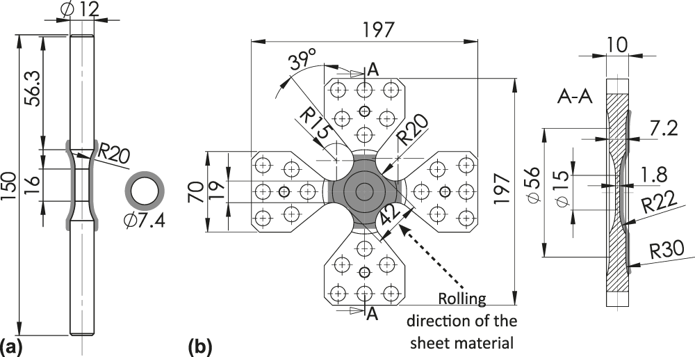
The uniaxial specimens were turned out of cylinders which were eroded from the rod material of 16Mo3 as well as of the bulk IN625mod material. In case of the cruciform specimens, the sheet material was used. The final shape was milled, and the mid section was machined by turning. Both final specimen geometries were subsequently sandblasted with alumina to achieve a rough surface for the final HVOF coating process. The uniaxial specimens were coated within the gauge length at the complete circumference with a thickness of 200 µm, which represents a fraction of 11% of the total cross section. At the cruciform specimens a 200 µm thick coating of IN625mod was also applied within the gauge area but only at one surface. Therefore, the coating has a fraction of 11% of the total thickness within the gauge area. The second surface of the substrate material was only mechanically grinded with SiC abrasive paper up to a grain size of 20 µm. The applied specimen geometries with marked coatings are shown in Fig. 3.
Technical drawing of the compound specimens, (a) cylindrical and (b) cruciform geometry. The coating within the figures is marked in gray. All dimensions are given in mm and include the coating thickness of 200 µm.

B. Test configuration and parameters
Uniaxial fatigue tests were carried out on a servohydraulic testing system with a load capacity of 100 kN (MTS Landmark 100, MTS, Eden Prairie, Minnesota). The heating of the gauge area of the cylindrical specimens was achieved by an inductive heating device (TRUMPF Hüttinger GmbH + Co. KG, Freidburg, Germany) and an induction coil placed around the gauge length, see Ref. Reference Andersson and Sjöström45. Temperature was measured by a thermocouple type K which was wrapped around the specimen surface as a ribbon Reference Beck, Hähner, Kühn, Rae, Affeldt, Andersson, Köster and Marchionni46 and additionally fixed in the center of the specimen by a silicon oxide ceramic fabric.
For the strain measurement, a water-cooled extensometer with alumina rods was attached on the specimen surface, see Refs. Reference Hoffmann and Biermann41 and Reference Kulawinski, Hoffmann, Lippmann, Lamprecht, Henkel and Biermann42 for more details. To obtain a homogenous temperature distribution, the specimen shoulders were cooled by water-cooled copper clamps. For the TMF tests, the same cooling configuration as for LCF was used.
To obtain the necessary test data for the TMF test control, 10 temperature cycles with zero stress control were carried out before each test. On the basis of three stable temperature cycles, the thermal expansion strain was determined and approximated by an exponential function. Thus, all TMF tests were carried out under mechanical strain control in accordance to the code of practice of TMF. Reference Beck, Hähner, Kühn, Rae, Affeldt, Andersson, Köster and Marchionni46–Reference Hähner, Rinaldi, Bicego, Affeldt, Brendel, Andersson, Beck, Klingelhöffer, Kühn, Köster, Loveday, Marchionni and Rae48 Two typical cases of thermo-mechanical loading were investigated, the in-phase (IP) loading without phase shift between the mechanical strain and the temperature cycle as well as the out-of-phase (OP) loading, which had a phase shift of 180°.
Both isothermal and TMF tests were carried out under mechanical strain control by using a triangular wave shape signal under symmetric push–pull conditions. The isothermal tests were performed in total strain control with a strain rate of 1 × 10⁻³ s−1 at temperatures of 200 and 500 °C. For the TMF tests carried out within the temperature interval of 200 and 500 °C, a constant heating and cooling rate of 5 K/s (i.e., a frequency f of 0.0083 Hz) was chosen. Thus, the strain rate depended on the mechanical strain amplitude. During the entire period of the fatigue tests, the temperature deviations to the setpoint temperature cycle were kept within ±3 K. The tested specimens and testing parameters are summarized in Table SI.
The biaxial-planar loading was investigated by means of a servohydraulic testing machine (Instron, High Wycombe, United Kingdom), which is presented in more detail by previous works of the authors’ group. Reference Kulawinski, Hoffmann, Lippmann, Lamprecht, Henkel and Biermann42,Reference Kulawinski, Weidner, Henkel and Biermann49,Reference Kulawinski, Henkel, Holländer, Thiele, Gampe and Biermann50 Cruciform specimens had a circular gauge area with a diameter of 15 mm and a reduced total thickness of 1.8 mm, including the coating of 0.2 mm. This specimen geometry is suitable for fatigue testing according to Pascoe and Villiers. Reference Pascoe and Villiers51 Within the gauge area, a concentration of the stress and strain with a nearly homogeneous distribution was achieved. Thus, crack initiation was mainly caused within the gauge area.
The biaxial-planar isothermal fatigue test configuration is described more in detail by the authors elsewhere. Reference Kulawinski, Hoffmann, Lippmann, Lamprecht, Henkel and Biermann42,Reference Kulawinski, Weidner, Henkel and Biermann49,Reference Kulawinski, Henkel, Holländer, Thiele, Gampe and Biermann50 In this configuration, the cruciform specimens were clamped into water-cooled grips and the gauge area was heated from one side with an inductive heating device (Hüttinger) by a cylindrical coil. The specimens were mounted with the coating on the side of the inductive heating. On the opposite surface, temperature and strain were measured by the attachment of one thermocouple type K and of a biaxial-orthogonal extensometer, respectively. In the previous work, it was demonstrated that this biaxial-planar test set up is suitable for isothermal and TMF testing. Reference Kulawinski, Hoffmann, Lippmann, Lamprecht, Henkel and Biermann42,Reference Kulawinski, Weidner, Henkel and Biermann49,Reference Kulawinski, Henkel, Holländer, Thiele, Gampe and Biermann50
The biaxial-planar isothermal fatigue behavior of the compound specimens was investigated as in the uniaxial loading case at temperatures of 200 and 500 °C. Also, a triangular wave shape signal for the strain-controlled tests under symmetric push–pull conditions was used. At each temperature, two strain amplitudes with the same strain rate of 1 × 10⁻³ s−1 and strain ratio
 $\Phi = \varepsilon _2^{{\rm{tot}}}{\rm{/}}\varepsilon _1^{{\rm{tot}}}$
of 1 were tested. This strain ratio Φ = 1 is typically called equibiaxial loading. The parameters of the isothermal biaxial-planar fatigue tests are summarized in Table SII.
C. Stress and strain calculation
The determination of the stress state within the gauge area of the cruciform specimen is a well-known problem of biaxial-planar testing which was solved by using the partial unloading method by the authors’ group for the investigation of the material behavior under static Reference Kulawinski, Nagel, Henkel, Hübner, Fischer, Kuna and Biermann52,Reference Kulawinski, Ackermann, Seupel, Lippmann, Henkel, Kuna, Weidner and Biermann53 and fatigue Reference Kulawinski, Hoffmann, Lippmann, Lamprecht, Henkel and Biermann42,Reference Kulawinski, Weidner, Henkel and Biermann49,Reference Kulawinski, Ackermann, Glage, Henkel and Biermann54,Reference Kulawinski55 loading. With this technique, the stresses in both axes are calculated by means of Hooke’s law for the plane stress state on the basis of elastic strain as well as the elastic constants Young’s modulus E and Poisson ratio νel. The Possion ratio νel was assumed to be 0.3 at both temperatures, and for the Young’s modulus the values were calculated by a rule of mixture, which takes the amount of the coating and substrate material within the cross sectional area into account. Therefore, a Young’s modulus of 204.6 GPa at 200 °C and 177.9 GPa at 500 °C were used.
The equivalent values of the stress and strain were calculated under the assumption of an isotropic material behavior and the distortion energy hypothesis according to von Mises. In particular, for the equivalent strain, the definition of an effective Poisson ratio according to Bannantine et al. Reference Bannantine, Comer and Handrock56 as well as a signed formulation of the equivalent strain according to Sonsino and Grubisic Reference Sonsino and Grubisic57 were used. In detail, the equations and definitions are presented in the previous work of the authors’ group. Reference Kulawinski, Hoffmann, Lippmann, Lamprecht, Henkel and Biermann42,Reference Kulawinski, Weidner, Henkel and Biermann49,Reference Kulawinski, Ackermann, Glage, Henkel and Biermann54,Reference Kulawinski55
IV. EXPERIMENTAL RESULTS AND DISCUSSION
A. Tensile tests
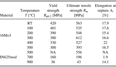
Both materials of the composite were characterized separately by uniaxial tensile tests with an initial strain rate of 1 × 10⁻³ s−1. The substrate material 16Mo3 was tested at RT, 100, 200, 300, 400, and 500 °C. Coating material IN625mod was characterized as bulk material, as shown in Fig. S1 at 500, 700, and 900 °C. The stress–strain curves for both materials were already presented in previous works. Reference Hoffmann and Biermann41,Reference Soltysiak, Selent, Roth, Abendroth, Hoffmann, Biermann and Kuna43,Reference Selent, Soltysiak, Roth, Abendroth, Hoffmann and Kuna44 A summary of the tensile properties is given in Table II. The substrate material 16Mo3 shows a decreasing yield strength with increasing temperature. For the ultimate tensile strength, 16Mo3 shows a maximum value at 300 °C, and above 300 °C the tensile strength is significantly decreasing. The elongation at the fracture is larger than 15% for all temperatures.
Uniaxial mechanical properties (mean values based on 3 tests at each temperature and material) of the substrate material of 16Mo3 and the bulk coating material IN625mod.

In contrast to the ductile material behavior of 16Mo3 for all temperatures, the coating material IN625mod shows a brittle linear-elastic material behavior at 500 °C. Therefore, no values for the yield strength and elongation at the fracture are available at 500 °C. With higher temperatures IN625mod gets more ductile so that the elongation at the fracture increases with increasing temperature. A contrary behavior occurs for the ultimate tensile strength with increasing temperature.
In particular, at 500 °C a completely different material behavior for the substrate material 16Mo3 (ductile) and coating material IN625mod (brittle) as well as a large difference in ultimate tensile strength occurs. These large differences in the material behavior of the substrate and coating material lead to a strong damage, in particular, at high strain amplitudes during the fatigue tests so that a premature failure of the composite material is to be expected.
B. Cyclic deformation curves of the bulk coating material IN625mod under uniaxial loading
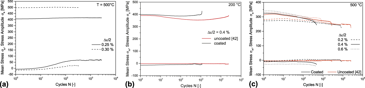
The coating material IN625mod was characterized under isothermal fatigue loading at 500 °C. The cyclic deformation behavior is shown in Fig. 4(a).
Cyclic deformation curves with the course of the stress amplitude and mean stress of the uniaxial fatigue tests of the (a) coating material IN625mod at 500 °C for two total strain amplitudes and of IN625 coated 16Mo3 and in comparison to the substrate material 16Mo3 at (b) 200 °C and (c) 500 °C.

The stress amplitudes for both strain amplitudes showed a stable cyclic behavior for the whole period of the fatigue tests. However, the mean stresses showed some variations. Within the first cycles, compressive mean stresses were present. During the fatigue tests, the mean stresses increased so that at failure, tensile means stresses were observed. This change from the compressive range (−25 MPa) into the tensile range (up to 65 MPa) can be attributed to the formation of Ni3(Nb, Al, Ti) (γ″-precipitates) and Ni2Cr superlattice phases. Reference Mukherjee, Sarkar, Barat, Jayakumar, Mahadevan and Rai58,Reference Kusabiraki, Komatsu and Ikeuchi59 Since the experiments on the coating material IN625mod were carried out without preliminary heat treatment of the specimens, the material was tested in a supersaturated solution condition, which is able to form precipitates and superstructures at 500 °C. Both γ″-precipitates and the Ni2Cr superlattice have a smaller unit cell than that of the γ-matrix, thus a volume contraction can occur, see Refs. Reference Mukherjee, Sarkar, Barat, Jayakumar, Mahadevan and Rai58–Reference Wilson and Ferrari61. The resulting behavior for such a volume contraction is known under creep loading as “negative creep”. Reference Reppich60,Reference Wilson and Ferrari61 For total strain controlled isothermal fatigue tests, a mean stress was caused. Reference Chen, Wang and Zhu32,Reference Kulawinski, Weidner, Henkel and Biermann49 Obviously, this effect was more pronounced at the low strain amplitude which induces small plastic strains. For the higher strain amplitude with increasing plastic strains the strain hardening behavior is more important for the development of the mean stress. Therefore, the formation of precipitates and superlattice have a lower impact on the mean stress at the higher strain amplitude. Reference Kulawinski, Weidner, Henkel and Biermann49
C. Cyclic deformation curves of the coated specimens under uniaxial isothermal and thermo-mechanical loading
Figures 4(b) and 4(c) show the cyclic deformation curves of the compound specimens at 200 and 500 °C.
The fatigue test at 200 °C shows a nearly stable cyclic behavior with a slightly decreasing stress amplitude up to 200 cycles. After that region, an increasing stress amplitude until failure occurs. An initial compressive mean stress was measured, which nearly disappeared during the fatigue test. The discontinuity within the curve of the mean stress at 400 cycles indicates damage of the coating. The uncoated reference test showed a more pronounced cyclic softening followed by a more pronouced cyclic hardening regime until final failure. The lifetime is more than one order higher.
At 500 °C, the cyclic deformation curves of the compound specimens are characterized for the first ten cycles by an initial stable behavior which was followed by a continuous decreasing stress amplitude until failure. The stress response at 500 °C was lower than that at 200 °C due to lower strength of the substrate material at 500 °C. Reference Hoffmann and Biermann41,Reference Kulawinski, Hoffmann, Lippmann, Lamprecht, Henkel and Biermann42 As in the case of the lower test temperature, initial compressive stresses were present at 500 °C for all strain amplitudes. For small strain amplitudes, the mean stresses disappeared during the test. However, at strain amplitudes above 0.2%, the mean stresses decreased continuously with increasing the number of cycles. Above 100 cycles, a rapid decrease was obtained which might be caused by degradation of the compound material and/or damage of the coating.
The comparison of the uncoated substrate material 16Mo3 which was investigated in the previous work Reference Kulawinski, Hoffmann, Lippmann, Lamprecht, Henkel and Biermann42 to the compound specimens shows higher stress amplitudes for the compound material for strain amplitudes above 0.2% at both temperatures due to the higher strength of the coating, see Fig. 4. Therefore, the coating has a supporting effect on the substrate material. As soon as a damage or failure in the coating occurred, the supporting effect was lost under tensile loading. However, under compressive loading, the effect remains preserved because the cracks were mechanically closed. Therefore, increasing negative mean stresses were measured for the compound material with ongoing damage. Furthermore, due to the early damage of the coating, the fatigue lives were reduced in comparison to the uncoated substrate material 16Mo3. At the strain amplitude of 0.2% at 500 °C, the compound material showed a smaller stress amplitude mainly due to its elastic behavior and the corresponding lower Young’s modulus of the coating material due to the presence of pores.
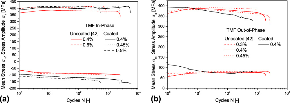
The cyclic deformation behavior under thermo-mechanical IP and OP loading is shown in Fig. 5 and compared to the behavior of the substrate material, which was already presented in the previous work of the authors’ group. Reference Kulawinski, Hoffmann, Lippmann, Lamprecht, Henkel and Biermann42
Cyclic deformation curves with the course of the stress amplitude and the mean stress of the uniaxial TMF tests of compound specimens and uncoated reference specimens under (a) IP loading and (b) OP loading.

The cyclic deformation curve under the TMF IP and OP loading cases is separately shown in Figs. 5(a) and 5(b). In the case of IP loading, the cyclic deformation curves show a primary cyclic hardening regime. This region was followed for a small mechanical strain amplitude of 0.4% by cyclic softening and final secondary hardening. However, for larger strain amplitudes, no cyclic softening occurred. Thus, a nearly stable cyclic behavior until failure was obtained. In comparison to the substrate material, 16Mo3 higher stress amplitudes were measured for the coated specimens and, therefore, the coating again provides a supporting effect. As expected for IP loading, the mean stresses are of compressive nature which furthermore continuously decreased during the TMF tests. However, the mean stresses within the compound material were about 35–50 MPa below those of the substrate material. Thus, the coating mainly provides the supporting effect under compressive loading at the lower temperature of the TMF cycle, i.e., at 200 °C. The sudden drop within the curve of the mean stress of the coated material at 0.4% indicates damage/rupture and failure of the coating. Nevertheless, the coating leads to an extension of the fatigue life.
In the TMF OP loading case, the cyclic deformation curves, see Fig. 5(b), show a continuous decrease of the stress amplitude for the compound specimen until the final failure occurred. After only a few cycles, drops within curve of the stress amplitude occurred, which were also visible in the mean stress curve. These drops can be attributed to local failure of the coating. Therefore, the supporting effect of the coating was only a few cycles present so that the stress amplitudes were only for the first ten cycles above those of the substrate material. As typical for TMF OP loading, the mean stress was for the whole fatigue tests of tensile nature. In the first cycle a significant tensile mean stress of 120 MPa was measured which was rapidly decreasing due to failure of the coating. Thus, the supporting effected of the coating was only noticeable at 200 °C and the maximum tensile loading. Within the cycles from 300 to 2000, the mean stress of the coated material nearly coincided with that of the substrate material. Following to this region, an increasing mean stress was measured until the final failure of the compound specimens occurred. Concomitant with the early damage and failure of the coating, the fatigue life was reduced in comparison to the uncoated substrate material.
D. Cyclic deformation curves under biaxial loading
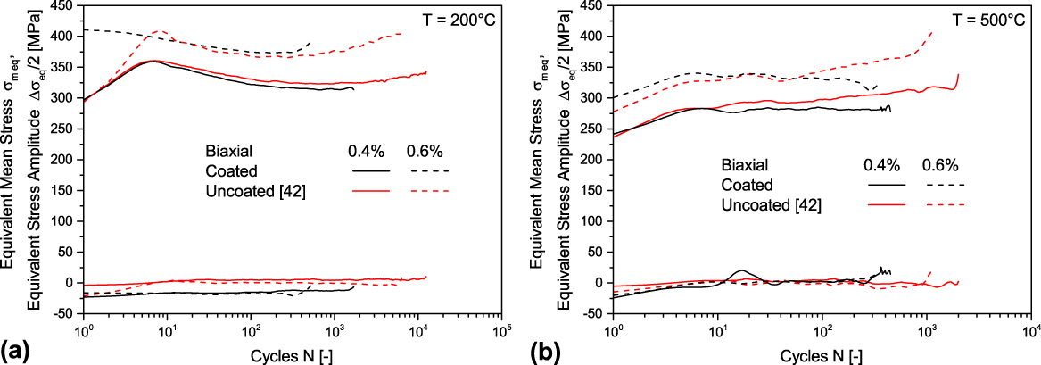
The fatigue behavior under biaxial-planar loading, i.e., the courses of the equivalent stress amplitude and the equivalent mean stress, is shown in Figs. 6(a) and 6(b) for the two test temperatures.
Cyclic deformation curves of the biaxial-planar fatigue test with the course of the equivalent stress amplitude and the mean stress of the compound specimens under biaxial-planar fatigue loading at (a) 200 °C and (b) 500 °C.

The comparison of the coated and the uncoated substrate material (produced as sheet material) under biaxial-planar fatigue loading at 200 °C shows a very good agreement for the equivalent strain amplitude of 0.4%. The behavior is characterized by primary hardening and a subsequent cyclic softening. However, the secondary hardening did not occur in the case of the coated specimen since failure occurred earlier. For the higher strain amplitude, the coated material showed no primary hardening under biaxial loading, in contrast to the uncoated material. Thus, only cyclic softening occurred. In this regime of cyclic softening, the curves coincide. Subsequently, damage within the coated material occurred, and finally the deviations between both specimens increased. The coated variants of the sheet and the rod materials showed significant differences due to variations of chemical composition, phases, and grain sizes, see Ref. Reference Kulawinski, Hoffmann, Lippmann, Lamprecht, Henkel and Biermann42. Therefore, the courses of the cyclic deformation curves are not directly compared here. Nevertheless, the fatigue lives were comparable.
Figure 6(b) shows the cyclic deformation curves at 500 °C. The equivalent stress amplitudes under biaxial-planar loading of the coated material show nearly similar primary hardening as the uncoated material. Within the first 10 to 20 cycles, a higher stress response of the compound material was measured at a strain amplitude of 0.6%. However, instead of following continuous hardening of the uncoated material, a cyclic stable fatigue behavior was observed for the coated specimen until failure occurred. Due to this different fatigue behavior, the stress amplitude of the compound material was for the main time of the fatigue test below that of the substrate material. As in the case of the isothermal fatigue tests at 200 °C, the coated rod material also showed a completely different cyclic deformation behavior, see also Ref. Reference Kulawinski, Hoffmann, Lippmann, Lamprecht, Henkel and Biermann42. However, comparable fatigue lives were observed.
Since biaxial-planar cyclic deformation behavior of the coated and uncoated materials was nearly the same, the stress calculation based on the partial unloading method as well as the distortion energy hypothesis according to von Mises are also suitable for the coated specimens.
E. Crack initiation and crack growth in the compound material
1. Uniaxial loading
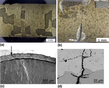
The crack initiation is located at the surface of the coating, at the interface to the substrate or within the thin coating, due to the microstructural inhomogeneities like pores and oxides, see Fig. 2, which serve as stress concentration sites as well as already present cracks within the material. Reference Al-Fadhli, Stokes, Hashmi and Yilbas18,Reference Puchi-Cabrera, Staia, Lesage, Chicot, La Barbera-Sosa and Ochoa-Prez24,Reference Padilla, Velsquez, Berrios and Puchi Cabrera26,Reference Chen, Huang, Wang and Zhu31,Reference Chen, Wang and Zhu32,Reference Huang, Wang, Zhu, Yuan and Wang39 According to Chen et al. Reference Chen, Huang, Wang and Zhu31 crack initiation took place within the coating and propagated to the interface. At the interface, the crack grew into the substrate material, and/or the crack deflected into the interface so that delamination occured. Therefore, the coating spalled off and further crack growth into the substrate material took place. Crack patterns and paths for the investigated compound specimens are shown in Fig. 7.
Investigation of the crack mechanism by (a) light optical microscopy of the surface of the composite material (TMF OP loading with strain amplitude of 0.4%) with a network of cracks and parts of flakes off coating. (b) A closer look to this TMF OP specimen on the crack network with circumferential cracks, which were merged by small longitudinal cracks. (c) SEM image secondary electron contrast which shows (arrow) a longitudinal crack in the coating and a delamination of the coating at the LCF specimen at 500 °C tested with a strain amplitude of 0.6%. (d) SEM image of the LCF specimen at 500 °C tested with a strain amplitude of 0.6% in back scatter electron contrast of a longitudinal crack with a crack initiation within the coating and a crack propagation into the substrate material as well as a crack deflection at the interface of the coating and substrate.

Typically, circumferential cracks were formed, see Figs. 7(a) and 7(b), which led to drops of the stress response during the fatigue tests as already visible in the cyclic deformation curves in Figs. 4(b), 4(c), and 5. In particular, this behavior was very pronounced for the TMF OP loading, see Fig. 5(b). The circumferential cracks were merged together by longitudinal cracks (along the loading direction), which yielded a network of cracks as shown in Fig. 7(b). Below the coating, the circumferential cracks were also merged together yielding delamination of the coating, see Fig. 7(c), so that the coating spalled off as shown in Figs. 7(a) and 7(b). Moreover, the cracks propagated also into the substrate material thus leading to the final failure. In Fig. 7(d), crack initiation within the coating is shown which is caused by an oxide particle. The following crack propagation showed both crack growth to the surface of the specimen as well as to the interface. At the interface, crack propagation into the substrate material as well as deflection of the crack path along the interface was observed. According to this investigation, the results of Chen and Huang et al. Reference Chen, Huang, Wang and Zhu31,Reference Chen, Wang and Zhu32,Reference Huang, Wang, Zhu, Yuan and Wang39 were confirmed and extended.
2. Biaxial-planar loading
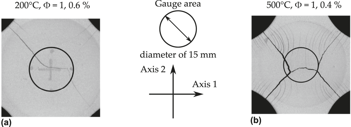
The crack initiation and growth under biaxial-planar loading showed the same crack mechanism as uniaxial loading. Therefore, only the crack networks were investigated in more detail in Fig. 8 for two examples.
Macroscopic crack orientation within the cruciform specimen under isothermal biaxial-planar fatigue at (a) 200 °C (Δεeq/2 = 0.6%) and (b) 500 °C (Δεeq/2 = 0.4%).

According to both Figs. 8(a) and 8(b), crack initiation occurred within the gauge area. Therefore, the biaxial-planar test rig satisfies the condition that the gauge area is the most stressed region due to temperature field, stress and strain distribution. Within the gauge area, the crack was oriented perpendicular to the loading axis 2. However, under the proportional loading condition of a strain ratio of 1, it is equally likely to an orientation perpendicular to axis 1. Reference Kulawinski55,Reference Brown and Miller62,Reference Itoh, Sakane and Ohnami63 This result agrees with the studies of Brown and Miller Reference Brown and Miller62 as well as Itoh Reference Itoh, Sakane and Ohnami63 who reported that the maximum normal strain plane is primarily responsible for the crack propagation direction. At the transition area to the edge of the specimen, the crack propagation direction changed into an inclination of 45° to the loading axes. Firstly, this direction is also a preferred direction according to the theory of Brown and Miller Reference Brown and Miller62 as well as Itoh. Reference Itoh, Sakane and Ohnami63 Another argument for the favored crack orientation of 45° to the loading axes is the temperature distribution within the cruciform specimen and the associated higher damage at the load carrying ring. Reference Kulawinski, Hoffmann, Lippmann, Lamprecht, Henkel and Biermann42 A damage simulation based on the Chaboche model for the cruciform specimen according to Wang et al. Reference Wang, Cui, Lyschik, Scholz, Berger and Oechsner64,Reference Wang, Cui, Scholz, Linn and Oechsner65 confirms these observations.
F. Fatigue lives
A stress reduction of 5% of the maximum stress was used to define the fatigue lives for isothermal fatigue tests at 200 °C and thermo-mechanical IP loading for the coated specimens as well as for the isothermal fatigue tests at 500 °C of the bulk coating material. A further criterion for fatigue life determination applied for the isothermal fatigue tests at 500 °C and for the TMF OP loading was based on the strong change of the tensile peak stress within the hysteresis loops. In the case of biaxial-planar testing, a 5% drop of the cruciform specimen stiffness was used to define the number of cycles to failure. Therefore, the same criteria as for the substrate material 16Mo3 investigated in the previous work Reference Kulawinski, Hoffmann, Lippmann, Lamprecht, Henkel and Biermann42 were used whereby comparability for the uncoated and the coated material was ensured. As a result from the cyclic deformation curves, a large stress drop was observed when failure occured so that the determined lifetimes according to the different criteria were comparable.
The fatigue lives of the coated specimens were described for the isothermal fatigue tests at 500 °C by the strain-based models according to Basquin and Manson–Coffin given in Eq. (1). Due to the limited data under isothermal fatigue at 200 °C and TMF OP loading as well as the small strain range for TMF IP loading, no representative fatigue life descriptions can be given for these conditions here.
 $${{\Delta \varepsilon } \mathord{\left/ {\vphantom {{\Delta \varepsilon } 2}} \right. \kern-\nulldelimiterspace} 2} = {{{\sigma _{\rm{f}}}} \over E}{\left( {2{N_{\rm{f}}}} \right)^b} + {\varepsilon _{\rm{f}}}{\left( {2{N_{\rm{f}}}} \right)^c}\quad ,$$
with the fatigue strength coefficient σf and exponent b as well as fatigue ductility coefficient εf and exponent c. The parameters of the Basquin and Manson–Coffin relationship for isothermal fatigue at 500 °C are given in Table III.
Parameters of the Basquin and Manson–Coffin relationships for isothermal fatigue of the coated substrate 16Mo3 steel at 500 °C.

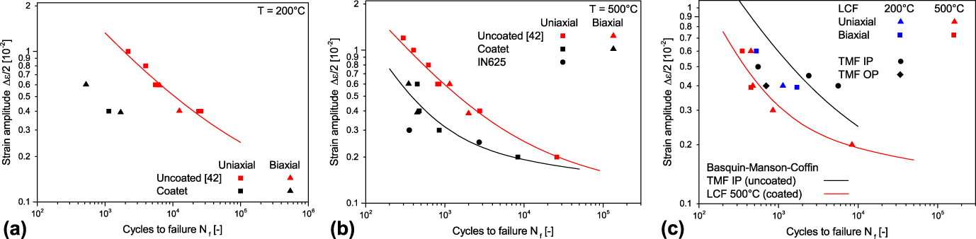
The isothermal fatigue lives of the coated specimens and the bulk coating material are compared in a strain amplitude versus the fatigue life plot in Figs. 9(a) and 9(b) to the uncoated substrate 16Mo3. Reference Kulawinski, Hoffmann, Lippmann, Lamprecht, Henkel and Biermann42
Isothermal lifetimes of the compound specimens with an IN625mod coating on the 16Mo3 substrate under unaixial as well as biaxial loading at both temperatures of (a) 200 °C and (b) 500 °C in comparison to the bulk coating material IN625mod and uncoated substrate material 16Mo3. (c) Uniaxial thermo-mechanical lifetimes under IP and OP loading of the compound specimens in comparison to the fatigue live curves of isothermal fatigue at 500 °C of the coated material and TMF IP loading of the uncoated substrate material 16Mo3. Reference Kulawinski, Hoffmann, Lippmann, Lamprecht, Henkel and Biermann42

The fatigue tests of the coated material at 200 °C show similar fatigue lives for biaxial and uniaxial loading [Fig. 9(a)]. In comparison to the uncoated material (uniaxial as well as biaxial data), the lifetimes were reduced by a factor of about eleven. Also at 500 °C, a reduction of the lifetimes of the coated specimens to the uncoated material was observed [Fig. 9(b)]. However, the lifetime reduction was just a factor of about 3–5 and, therefore, smaller than at 200 °C. Due to the strong oxidation of the substrate material at 500 °C, an oxide layer at the surface is formed early, which leads to a premature crack initiation. Therefore at 500 °C, for both the substrate as well as the composite material with the coating, a rapid crack initiation occurs. After the crack initiation in the substrate and in the compound material, a fast short crack growth under oxidizing atmosphere takes place until the criterion for fatigue life definition is fulfilled. This results in a smaller fatigue life reduction of the compound to the substrate material at 500 °C as than for 200 °C. Furthermore, there was no influence of the stress state of the loading on the lifetimes at 500 °C. Thus, biaxial-planar fatigue tests have nearly the same lifetime as uniaxial tests. At 500 °C, the bulk coating material IN625mod has the shortest fatigue lives which can be attributed to the pores, oxides, and crack-like bonding defects. Due to the microstructural inhomogeneities, there was a very fast crack initiation so that the lifetime was significantly determined by crack growth. Reference Al-Fadhli, Stokes, Hashmi and Yilbas18,Reference Puchi-Cabrera, Staia, Lesage, Chicot, La Barbera-Sosa and Ochoa-Prez24,Reference Padilla, Velsquez, Berrios and Puchi Cabrera26,Reference Chen, Huang, Wang and Zhu31,Reference Chen, Wang and Zhu32,Reference Huang, Wang, Zhu, Yuan and Wang39
As already reported in the previous work, Reference Kulawinski, Hoffmann, Lippmann, Lamprecht, Henkel and Biermann42 the lifetimes of the rod and sheet materials are comparable, despite the differences in the chemical composition and the microstructure. Moreover, the distortion energy hypothesis according to von Mises was suitable to calculate an equivalent strain, which gives a very good correlation between the uniaxial and the biaxial-planar proportional equibiaxial loading cases. Moreover, the coated material can also be described by the distortion energy hypothesis by von Mises as the case of the substrate material 16Mo3 reported in the previous work Reference Kulawinski, Hoffmann, Lippmann, Lamprecht, Henkel and Biermann42 and as often reported in the literature. Reference Kulawinski, Henkel, Holländer, Thiele, Gampe and Biermann50,Reference Kulawinski55,Reference Itoh, Sakane and Ohnami63,Reference Łagoda, Macha and Sakane66–Reference Ogata69 Most often, this is limited to the proportional loading case with the strain ratio between the two axes of 1 called equibiaxial loading.
The TMF lives of the coated material are compared in Fig. 9(c) to isothermal tests for both temperatures as well as the lifetimes of TMF IP loading of the substrate material.
In general, the number of cycles to failure for the TMF IP loading were higher than for the OP loading. At a high strain amplitude of 0.5% of TMF IP loading and for the TMF OP loading (0.4%), the fatigue lives fall within the scatter band of isothermal tests for both temperatures. However, the lower strain amplitudes under TMF IP loading yielded a remarkable extension of the fatigue lives. These lifetimes even exceed the number of cycles to failure for the uncoated material under TMF IP loading. Therefore, the supporting effect of the coating leads to an improvement compared to the substrate material 16Mo3. The supporting effect probably relieves the substrate material, so that the damage caused by creep fatigue at 500 °C was reduced. The reason for this behavior was the higher compressive mean stress of the compound material in comparison to the uncoated substrate. Obviously, this effect gets lost with increasing strain amplitude at which the coating breaks early. In the case of the TMF OP loading of the coated specimen, the mean stress was of tensile nature so that no positive supporting effect from the coating occurred. In comparison, the fatigue life curve for the coated material at 500 °C (marked by a red line) is added in Fig. 9(c), and it appears that a conservative estimation for all TMF tests of the coated material is possible.
V. CONCLUSIONS
In this study, the uniaxial and biaxial-planar isothermal as well as the TMF behavior of compound specimens of the substrate material 16Mo3 with an IN625mod coating sprayed by the HVOF process was investigated. The main results are:
-
(1) Because the coating was tested in a supersaturated condition, the formation of γ″ and Ni2 Cr superlattice precipitates occured during isothermal fatigue tests at 500 °C, which yielded tensile mean stresses in the strain-controlled fatigue tests.
-
(2) The supporting effect of the coating led to higher tensile stress than in the uncoated substrate material.
-
(3) The stress drops within the cyclic deformation curves, i.e., in the stress amplitudes and the means stresses can be attributed to the formation of circumferential cracks within the coating.
-
(4) The cyclic deformation curves of the coated material under biaxial-planar fatigue loading were comparable to those of the uncoated material.
-
(5) The crack initiation occurred preferentially at the surface of the coating and/or at the interface to the substrate. The cracks proceeded very quickly within the coating. Therefore, under isothermal fatigue and TMF OP loading, the fatigue lives were significantly reduced compared to the uncoated material. For the TMF IP loading at small strain amplitudes, however, an extension of fatigue life by the coating was achieved.
-
(6) The numbers of cycles to failure for the equibiaxial isothermal loading coincide with the values of the uniaxial tests. Therefore, the equivalent strain hypothesis according to von Mises is suitable for the correlation of the biaxial and the uniaxial loading cases for proportional loading cases. Thus, a suitable technique is presented to study any biaxial loading situation.
Supplementary Material
To view supplementary material for this article, please visit https://doi.org/10.1557/jmr.2017.344.
ACKNOWLEDGMENTS
The authors acknowledge the financial support of the European Union (European Fund for Regional Development) and the Free State of Saxony within Saxon Excellence Initiative ADDE (ADDE under funding grant in the subproject TP 15 No. 13852/2337). A special thank goes to Professor M. Sakane, Ritsumeikan University, Kyoto, Japan, for the helpful remarks as well as the discussion. Furthermore, we want to thank Dipl.-Ing. R. Kolmorgen for experimental support.