1 Introduction
Layered flows are often encountered in many geophysical and engineering problems. During summer, sharp thermoclines in lakes and oceans typically divide warmer (lighter) water above from the colder (denser) water below (Woods Reference Woods1968), thereby producing an approximately ‘two-layered’ system. Zonal jets, consisting of layers of nearly constant potential vorticity, are ubiquitous in the terrestrial atmosphere and in the oceans, as well as in the atmospheres of the gas giant planets (Scott & Dritschel Reference Scott and Dritschel2012). Multilayered Poiseuille flows are often encountered in engineering, especially during co-extrusion, lamination and coating processes (Moyers-Gonzalez & Frigaard Reference Moyers-Gonzalez and Frigaard2004). An interface separating two neighbouring layers supports neutral progressive wave(s). For example, the interface between air and water supports surface gravity waves, while that between cold and warm water supports interfacial gravity waves. A fluid flow can become unstable when multiple interfaces are present. The ensuing instability can potentially cause transition to turbulence, a problem of immense importance in nearly all sub-fields of fluid dynamics.
Normal-mode instabilities in homogeneous and density-stratified shear layers (e.g. Rayleigh/Kelvin–Helmholtz, Holmboe, Taylor–Caulfield instabilities) can be explained through resonant interaction between two interfacial waves (Taylor Reference Taylor1931; Bretherton Reference Bretherton1966; Baines & Mitsudera Reference Baines and Mitsudera1994; Caulfield Reference Caulfield1994; Heifetz & Methven Reference Heifetz and Methven2005; Guha & Lawrence Reference Guha and Lawrence2014). Recently Guha & Lawrence (Reference Guha and Lawrence2014) (hereafter GL14) proposed a generalized theory of two interacting linear waves, known as the ‘wave interaction theory (WIT)’. WIT adds to the mechanistic understanding of normal-mode shear instabilities. According to WIT, shear instabilities arise due to synchronization of two interfacial waves (and not simply due to resonance). Drawing analogies from coupled oscillator synchronization, WIT extends the wave interaction formalism to accommodate non-normal (or non-modal) instabilities as well. It reveals that, due to non-normality, shear instabilities can lead to large transient growths in interfacial wave amplitudes, often surpassing normal-mode growth by a few orders of magnitude. Standard linear stability theory based on a normal-mode ansatz would fail to capture this behaviour. GL14 showed that such large growth could arise if the normal-mode ansatz is not imposed on the governing partial differential equations (PDEs). They found that the underlying dynamical system describing the interacting wave amplitudes and phases is highly nonlinear, which explains the large transient growths. Although the mechanism of transient growth due to non-normality is well understood (Trefethen et al. Reference Trefethen, Trefethen, Reddy and Driscoll1993; Schmid & Henningson Reference Schmid and Henningson2001), WIT provides a simple mechanistic explanation in a minimal setting with two waves.
The main goal of this paper is to study linear instabilities that arise via multiple wave interactions without limiting the analysis to the normal-mode formalism. Unfettered by the conventional normal-mode ansatz, both normal-mode and non-modal instabilities are thus explored. WIT theory has so far been limited to the interaction between just two linear interfacial waves. While two-wave interaction provides the mechanistic picture of well known shear instabilities, many physical scenarios in the oceanic and atmospheric systems may arise where the use of just two interfaces (or waves) could be an unrealistic oversimplification. Moreover, the phase-portrait of two-wave WIT is analogous to coupled oscillators and is therefore very simple. For wavenumbers satisfying ‘linearly unstable’ criteria, the phase-portrait exhibits two fixed points: one is a stable node (growing normal mode) while the other is an unstable node (decaying normal mode) (Heifetz, Bishop & Alpert Reference Heifetz, Bishop and Alpert1999; Guha & Lawrence Reference Guha and Lawrence2014). One can therefore anticipate richer nonlinear dynamics when multiple interfaces are considered. This paper deals with developing a multi-interface framework and investigating the resulting dynamical system. As shown, the extension from two interfaces to multiple interfaces turns out to be quite non-trivial. Such multilayered systems are themselves often idealized models of real-world fluid systems. In reality quantities of interest vary continuously; modeling base states, which are continuous functions, as piecewise continuous (which is needed for multilayered systems) is indeed a simplification. Yet, such simplifications often help, and in many instances are indeed necessary for providing the required analytical tractability in order to develop improved insights and useful results. For example, in (homogeneous) shear flows, the base-flow vorticity varies continuously, but for greater analytical tractability it can often be assumed to be layerwise constant. Likewise, flows in the atmosphere and the oceans are often modeled as multilayered shallow-water systems since this provides a simplified representation, while retaining their key dynamical features (Vallis Reference Vallis2006). In this paper we first develop a general framework for multilayered systems. Then we specifically consider and provide computational results for the ‘saw-tooth’ jet problem, which is an approximate model for the zonal-jet structure in planetary atmospheres. Furthermore, the saw-tooth jet exhibits three interfaces and possesses kinematic and geometric symmetry.
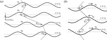
(a) Schematic of the general set-up. (b) The saw-tooth jet profile, which produces a three-interface problem with symmetry.

2 The general model
We consider an inviscid, incompressible, 2D flow with
 $M$
interfaces, which are located at
 $z=z_{1},z_{2},\ldots ,z_{M}$
(see figure 1
a). The last/boundary interfaces could be followed by an infinite medium. The background velocity
 $U$
is parallel to the
 $x$
axis and is a piecewise continuous function of
 $z$
. Density may be constant or variable; if variable it is assumed to be layerwise constant and decreasing with the vertically upward pointing coordinate
 $z$
, implying stable stratification. When sinusoidal streamwise perturbations are added to such a layered fluid system, the resultant wave field becomes such that the waves propagate only along the interfaces (Sutherland Reference Sutherland2010). The generation mechanism of this wave field can be described by the Poisson equation relating the perturbation stream-function
 $\unicode[STIX]{x1D713}(x,z,t)$
and the perturbation vorticity
 $q(x,z,t)$
(Drazin & Reid Reference Drazin and Reid2004; Sutherland Reference Sutherland2010):
 $$\begin{eqnarray}\unicode[STIX]{x1D6FB}^{2}\unicode[STIX]{x1D713}=q.\end{eqnarray}$$
We assume
 $\unicode[STIX]{x1D713}$
and
 $q$
to represent sinusoidal disturbances along the
 $x$
direction. Furthermore, the disturbances are monochromatic with a wavenumber
 $\unicode[STIX]{x1D6FC}$
. This allows us to apply the Fourier ansatzes
 $q=\text{Re}\{\hat{q}(z,t)\text{e}^{\text{i}\unicode[STIX]{x1D6FC}x}\}$
and
 $\unicode[STIX]{x1D713}=\text{Re}\{\hat{\unicode[STIX]{x1D713}}(z,t)\text{e}^{\text{i}\unicode[STIX]{x1D6FC}x}\}$
:
 $$\begin{eqnarray}\left(\frac{\unicode[STIX]{x2202}^{2}}{\unicode[STIX]{x2202}z^{2}}-\unicode[STIX]{x1D6FC}^{2}\right)\unicode[STIX]{x1D713}=q.\end{eqnarray}$$
The above equation is a regular, non-homogeneous Sturm–Liouville problem with homogeneous boundary conditions:
 $\unicode[STIX]{x1D713}\rightarrow 0$
as
 $z\rightarrow \pm \infty$
. It can be solved by inverting the linear operator on the left-hand side of (2.2), yielding
 $$\begin{eqnarray}\unicode[STIX]{x1D713}=\int _{\mathscr{B}}\mathscr{G}(s,z;\unicode[STIX]{x1D6FC})q\,\text{d}s,\end{eqnarray}$$
where
 $\mathscr{B}$
is the field domain and
 $\mathscr{G}(s,z;\unicode[STIX]{x1D6FC})$
is the Green’s function satisfying
 $\unicode[STIX]{x2202}^{2}\mathscr{G}/\unicode[STIX]{x2202}z^{2}-\unicode[STIX]{x1D6FC}^{2}\mathscr{G}=\unicode[STIX]{x1D6FF}(z-s)$
, with the appropriate boundary conditions. Our domain is unbounded (extending to
 $\pm \infty$
), which yields
 $\mathscr{G}=-\text{e}^{-\unicode[STIX]{x1D6FC}|z-s|}/(2\unicode[STIX]{x1D6FC})$
.
In inviscid flows, a particle on an interface
 $\unicode[STIX]{x1D702}_{j}=\unicode[STIX]{x1D702}(x,z_{j},t)$
stays on that interface forever. This is expressed in terms of the kinematic condition
 $$\begin{eqnarray}\frac{\text{D}\unicode[STIX]{x1D702}_{j}}{\text{D}t}\equiv \frac{\unicode[STIX]{x2202}\unicode[STIX]{x1D702}_{j}}{\unicode[STIX]{x2202}t}+U_{j}\frac{\unicode[STIX]{x2202}\unicode[STIX]{x1D702}_{j}}{\unicode[STIX]{x2202}x}=w_{j}.\end{eqnarray}$$
The above equation is the ‘linearized’ kinematic condition (hence
 $\text{D}/\text{D}t$
is the linearized material derivative operator) because the background velocity,
 $U_{j}\equiv U(z_{j})$
, is known.
 $U_{j}$
should not be confused with the perturbation
 $x$
-velocity at the
 $j$
th interface, which is
 $u_{j}=\unicode[STIX]{x2202}\unicode[STIX]{x1D713}_{j}/\unicode[STIX]{x2202}z$
. The quantity
 $w_{j}=w(x,z_{j},t)$
is the
 $z$
-velocity at the
 $j$
th interface. Noting that
 $w=-\unicode[STIX]{x2202}\unicode[STIX]{x1D713}/\unicode[STIX]{x2202}x=-\text{i}\unicode[STIX]{x1D6FC}\unicode[STIX]{x1D713}$
, the linearized kinematic condition at the
 $j$
th interface can be expressed in terms of (2.3) as
 $$\begin{eqnarray}\frac{\text{D}\unicode[STIX]{x1D702}_{j}}{\text{D}t}=\frac{\text{i}}{2}\int _{\mathscr{B}}\text{e}^{-\unicode[STIX]{x1D6FC}|z_{j}-s|}q\,\text{d}s.\end{eqnarray}$$
Until this point we have only worked with different kinematic equations. Dynamics can enter into the problem through the
 $q$
term. In 2D, inviscid, Boussinesq flows, the linearized evolution equation for the perturbation vorticity reads (Rabinovich et al.
Reference Rabinovich, Umurhan, Harnik, Lott and Heifetz2011; Carpenter et al.
Reference Carpenter, Tedford, Heifetz and Lawrence2013)
 $$\begin{eqnarray}\frac{\text{D}q}{\text{D}t}=-w\frac{\text{d}Q}{\text{d}z}+N^{2}\frac{\unicode[STIX]{x2202}\unicode[STIX]{x1D702}}{\unicode[STIX]{x2202}x},\end{eqnarray}$$
where
 $Q=\text{d}U/\text{d}z$
is the background vorticity and
 $N(z)=\sqrt{-(g/\unicode[STIX]{x1D70C}_{0})\text{d}\bar{\unicode[STIX]{x1D70C}}/\text{d}z}$
is the background buoyancy frequency (
 $\unicode[STIX]{x1D70C}_{0}$
is the reference density,
 $\bar{\unicode[STIX]{x1D70C}}$
is the background density and
 $g$
is gravity). The first term on the right-hand side of (2.6) is known as the barotropic generation of vorticity (which is a kinematic process), while the second term implies baroclinic generation (which is a dynamic process). There are even other means of dynamic generation of vorticity, e.g. magnetic fields (Heifetz et al.
Reference Heifetz, Mak, Nycander and Umurhan2015), surface tension (Biancofiore, Gallaire & Heifetz Reference Biancofiore, Gallaire and Heifetz2015), etc.
As an example we consider the simplest case where the flow is homogeneous/barotropic, i.e. we set
 $N=0$
in (2.6). Along with this equation we use the linearized kinematic condition
 $\text{D}\unicode[STIX]{x1D702}/\text{D}t=w$
, yielding
 $$\begin{eqnarray}\frac{\text{D}q}{\text{D}t}=-\frac{\text{D}}{\text{D}t}\left(\unicode[STIX]{x1D702}\frac{\text{d}Q}{\text{d}z}\right)\quad \text{which}~\text{implies}~q=-\unicode[STIX]{x1D702}\frac{\text{d}Q}{\text{d}z}.\end{eqnarray}$$
In flows where the background vorticity
 $Q$
is layered, one can approximate
 $Q$
by a piecewise constant function. This leads to a considerable analytical simplification because the quantity
 $\text{d}Q/\text{d}z$
yields delta functions at each isolated discontinuity
 $z=z_{1},z_{2},\ldots ,z_{M}$
:
 $$\begin{eqnarray}\frac{\text{d}Q}{\text{d}z}=\mathop{\sum }_{j=1}^{M}\unicode[STIX]{x0394}Q_{j}\unicode[STIX]{x1D6FF}(z-z_{j}).\end{eqnarray}$$
Here
 $\unicode[STIX]{x0394}Q_{j}\equiv Q(z_{j}^{+})-Q(z_{j}^{-})$
is the jump in
 $Q$
at the discontinuity
 $z_{j}$
. Equation (2.8) is substituted in (2.7), and then the resultant expression is substituted in (2.5) to yield
 $$\begin{eqnarray}\frac{\text{D}\unicode[STIX]{x1D702}_{j}}{\text{D}t}=\mathop{\sum }_{k=1}^{M}\tilde{w}_{k}(x,t)\text{e}^{-\unicode[STIX]{x1D6FC}z_{jk}},\end{eqnarray}$$
where
 $\tilde{w}_{k}=-\text{i}\unicode[STIX]{x1D702}_{k}\unicode[STIX]{x0394}Q_{k}/2$
and
 $z_{jk}=|z_{j}-z_{k}|$
. We note here that
 $w_{j}$
of (2.4) has been expressed in (2.9) as the sum of
 $z$
-velocity contributions from all the
 $M$
interfaces, including itself.
In order to convert (2.9) into a system of ordinary differential equations, we will assume Fourier ansatzes (and not the conventional normal-mode ansatzes):
 $\unicode[STIX]{x1D702}_{j}(x,t)=\text{Re}\{A_{\unicode[STIX]{x1D702}_{j}}(t)\text{e}^{\text{i}(\unicode[STIX]{x1D6FC}x+\unicode[STIX]{x1D719}_{\unicode[STIX]{x1D702}_{j}}(t))}\}$
and
 $\tilde{w}_{j}(x,t)=\text{Re}\{A_{w_{j}}(t)\text{e}^{\text{i}(\unicode[STIX]{x1D6FC}x+\unicode[STIX]{x1D719}_{w_{j}}(t))}\}$
, where
 $A_{\unicode[STIX]{x1D702}_{j}}$
,
 $A_{w_{j}}$
,
 $\unicode[STIX]{x1D719}_{\unicode[STIX]{x1D702}_{j}}$
and
 $\unicode[STIX]{x1D719}_{w_{j}}$
are arbitrary real functions of
 $t$
. We define the amplitude ratios
 $\unicode[STIX]{x1D6FA}_{j}\equiv A_{w_{j}}/A_{\unicode[STIX]{x1D702}_{j}}$
and
 $R_{jk}\equiv A_{\unicode[STIX]{x1D702}_{k}}/A_{\unicode[STIX]{x1D702}_{j}}$
, and the phase differences
 $\unicode[STIX]{x1D6F7}_{jk}\equiv \unicode[STIX]{x1D719}_{w_{k}}-\unicode[STIX]{x1D719}_{\unicode[STIX]{x1D702}_{j}}$
. These definitions lead to the following identities, which will be used in the equations appearing later on in the article:
 $$\begin{eqnarray}\displaystyle \left.\begin{array}{@{}c@{}}(\text{i})~R_{jk}=1/R_{kj},\quad (\text{ii})~R_{jk}=R_{jl}R_{lk},\quad (\text{iii})~\unicode[STIX]{x1D6F7}_{jk}=\unicode[STIX]{x1D6F7}_{kk}+\unicode[STIX]{x1D719}_{\unicode[STIX]{x1D702}_{k}}-\unicode[STIX]{x1D719}_{\unicode[STIX]{x1D702}_{j}},\\ (\text{iv})~\unicode[STIX]{x1D6F7}_{jk}=\unicode[STIX]{x1D6F7}_{jj}+\unicode[STIX]{x1D6F7}_{kk}-\unicode[STIX]{x1D6F7}_{kj},\quad (\text{v})~\unicode[STIX]{x1D6F7}_{jk}=\unicode[STIX]{x1D6F7}_{jl}+\unicode[STIX]{x1D6F7}_{lk}-\unicode[STIX]{x1D6F7}_{ll},\\ (\text{vi})~\unicode[STIX]{x1D6F7}_{jk}=\unicode[STIX]{x1D6F7}_{kk}+\unicode[STIX]{x1D6F7}_{jl}-\unicode[STIX]{x1D6F7}_{kl}.\end{array}\right\} & & \displaystyle\end{eqnarray}$$
The above-mentioned variables have the following range of values:
 $R_{jk}\in (0,\infty )$
,
 $\unicode[STIX]{x1D6FA}_{j}\in (0,\infty )$
and
 $\unicode[STIX]{x1D6F7}_{jk}\in [-\unicode[STIX]{x03C0},\unicode[STIX]{x03C0}]$
, where
 $j$
and
 $k$
are
 $1,2,\ldots ,M$
. Waves whose intrinsic propagation is leftward have
 $\unicode[STIX]{x1D6F7}_{jj}=\unicode[STIX]{x03C0}/2$
, while those propagating rightward have
 $\unicode[STIX]{x1D6F7}_{jj}=-\unicode[STIX]{x03C0}/2$
(the reason is explained below). Substitution of the Fourier ansatzes for
 $\unicode[STIX]{x1D702}_{j}$
and
 $\tilde{w}_{j}$
in (2.9) produces
 $$\begin{eqnarray}\displaystyle & \displaystyle {\dot{A}}_{\unicode[STIX]{x1D702}_{j}}=\mathop{\sum }_{k=1}^{M}\unicode[STIX]{x1D6FA}_{k}A_{\unicode[STIX]{x1D702}_{k}}\cos \left(\unicode[STIX]{x1D6F7}_{jk}\right)\text{e}^{-\unicode[STIX]{x1D6FC}z_{jk}}, & \displaystyle\end{eqnarray}$$
 $$\begin{eqnarray}\displaystyle & \displaystyle \dot{\unicode[STIX]{x1D719}}_{\unicode[STIX]{x1D702}_{j}}=-\unicode[STIX]{x1D6FC}U_{j}+\mathop{\sum }_{k=1}^{M}\unicode[STIX]{x1D6FA}_{k}R_{jk}\sin \left(\unicode[STIX]{x1D6F7}_{jk}\right)\text{e}^{-\unicode[STIX]{x1D6FC}z_{jk}}, & \displaystyle\end{eqnarray}$$
where
 $j=1,2,\ldots ,M$
. While
 ${\dot{A}}_{\unicode[STIX]{x1D702}_{j}}$
in (2.11) is the rate of change of wave amplitude,
 $-\dot{\unicode[STIX]{x1D719}}_{\unicode[STIX]{x1D702}_{j}}$
in (2.12) implies the wave frequency.
 $\unicode[STIX]{x1D6FA}_{k}$
has the dimensions of frequency, and is in fact the magnitude of the intrinsic frequency of an interfacial wave in isolation. This can be shown as follows. Consider a system with a single interface, i.e.
 $M=1$
in (2.11) and (2.12). Since a wave cannot grow on its own, we must have
 ${\dot{A}}_{\unicode[STIX]{x1D702}}=0$
(index dropped for convenience), thereby implying
 $\unicode[STIX]{x1D6F7}=\pm \unicode[STIX]{x03C0}/2$
. In (2.12)
 $M=1$
also implies
 $R=1$
, hence this equation becomes
 $\dot{\unicode[STIX]{x1D719}}_{\unicode[STIX]{x1D702}}=-\unicode[STIX]{x1D6FC}U\pm \unicode[STIX]{x1D6FA}$
. In the absence of background velocity/Doppler shift we have
 $\dot{\unicode[STIX]{x1D719}}_{\unicode[STIX]{x1D702}}=\pm \unicode[STIX]{x1D6FA}$
, hence
 $\unicode[STIX]{x1D6FA}$
is indeed the intrinsic frequency of an interfacial wave in isolation. The positive and negative signs respectively imply leftward and rightward moving waves. Usually the value of
 $\unicode[STIX]{x1D6FA}$
comes from the dynamics, and is obtained from the dispersion relation
 ${\mathcal{D}}(\unicode[STIX]{x1D6FA},\unicode[STIX]{x1D6FC})=0$
. For example,
 $\unicode[STIX]{x1D6FA}$
of a long interfacial wave existing at the interface of two fluid layers of different densities (layer thicknesses respectively being
 $h_{1}$
and
 $h_{2}$
) under the Boussinesq approximation is
 $\unicode[STIX]{x1D6FC}[g^{\prime }h_{1}h_{2}/(h_{1}+h_{2})]^{1/2}$
(Sutherland Reference Sutherland2010), where
 $g^{\prime }$
is the reduced gravity.
It is convenient to define the growth rate
 $\unicode[STIX]{x1D70E}_{j}$
of the
 $j$
th interfacial wave as follows:
 $$\begin{eqnarray}\unicode[STIX]{x1D70E}_{j}\equiv {\dot{A}}_{\unicode[STIX]{x1D702}_{j}}/A_{\unicode[STIX]{x1D702}_{j}}=\mathop{\sum }_{k=1}^{M}\unicode[STIX]{x1D6FA}_{k}R_{jk}\cos \left(\unicode[STIX]{x1D6F7}_{jk}\right)\text{e}^{-\unicode[STIX]{x1D6FC}z_{jk}}.\end{eqnarray}$$
Equations (2.11)–(2.12) or (2.12)–(2.13) emphasize the fact that the growth rate
 $\unicode[STIX]{x1D70E}_{j}$
and frequency
 $-\dot{\unicode[STIX]{x1D719}}_{\unicode[STIX]{x1D702}_{j}}$
of a wave at the
 $j$
th interface are governed by the linear interaction of all interfacial waves present in the system. Moreover the interaction model (2.11)–(2.12) is essentially kinematic; the physics or dynamics is contained only in the
 $\unicode[STIX]{x1D6FA}_{k}$
terms. The advantage of being physics-independent is that the model is applicable to a wide variety of problems.
It is convenient to recast (2.11)–(2.12) in terms of
 $R_{jk}$
and
 $\unicode[STIX]{x1D6F7}_{jk}$
:
 $$\begin{eqnarray}\displaystyle & \displaystyle {\dot{R}}_{jk}=R_{jk}\mathop{\sum }_{l=1}^{M}\unicode[STIX]{x1D6FA}_{l}\{R_{kl}\cos \left(\unicode[STIX]{x1D6F7}_{kl}\right)\text{e}^{-\unicode[STIX]{x1D6FC}z_{kl}}-R_{jl}\cos \left(\unicode[STIX]{x1D6F7}_{jl}\right)\text{e}^{-\unicode[STIX]{x1D6FC}z_{jl}}\}, & \displaystyle\end{eqnarray}$$
 $$\begin{eqnarray}\displaystyle & \displaystyle \dot{\unicode[STIX]{x1D6F7}}_{jk}=\unicode[STIX]{x1D6FC}\left(U_{j}-U_{k}\right)+\mathop{\sum }_{l=1}^{M}\unicode[STIX]{x1D6FA}_{l}\{R_{kl}\sin \left(\unicode[STIX]{x1D6F7}_{kl}\right)\text{e}^{-\unicode[STIX]{x1D6FC}z_{kl}}-R_{jl}\sin \left(\unicode[STIX]{x1D6F7}_{jl}\right)\text{e}^{-\unicode[STIX]{x1D6FC}z_{jl}}\}, & \displaystyle\end{eqnarray}$$
where both
 $j$
and
 $k$
are
 $1,2,\ldots ,M$
. The above equation-set represents an autonomous, nonlinear dynamical system in
 $R_{jk}$
and
 $\unicode[STIX]{x1D6F7}_{jk}$
of dimension
 $2M-2$
. Following the convention of GL14 we will refer to the model given by (2.14)–(2.15) as WIT. While the WIT equations of GL14 (their (3.9)–(3.12)) are limited to two interfaces, here we have generalized the problem to
 $M$
interfaces. We should note the apparently surprising nonlinearity in the WIT equations given that they are derived from (2.9), which is a linear PDE. It should be further noted that the WIT equations of GL14, being the two-interface version of (2.14)–(2.15), are also nonlinear. However, the phase space of GL14 is limited in its richness since the dynamical system is only 2D.
The fixed points of (2.14)–(2.15) are of particular interest. In (2.15), the condition
 $\dot{\unicode[STIX]{x1D6F7}}_{jk}=0$
implies
 $\dot{\unicode[STIX]{x1D719}}_{\unicode[STIX]{x1D702}_{j}}=\dot{\unicode[STIX]{x1D719}}_{\unicode[STIX]{x1D702}_{k}}$
(by using identity (iii) of (2.10)), which means phase-locking of the waves located at the
 $j$
th and
 $k$
th interfaces. Furthermore, if
 $\unicode[STIX]{x1D70E}_{j}=\unicode[STIX]{x1D70E}_{k}=\text{const.}$
, the amplitudes of all the waves present in the system will have exponential growth or decay at the same rate. The condition
 ${\dot{R}}_{jk}=0$
in (2.14) implies
 $\unicode[STIX]{x1D70E}_{j}=\unicode[STIX]{x1D70E}_{k}$
, since
 ${\dot{R}}_{jk}=R_{jk}(\unicode[STIX]{x1D70E}_{k}-\unicode[STIX]{x1D70E}_{j})$
. This is the growth rate that would have been obtained if the normal-mode ansatz were substituted in (2.9) instead of the Fourier ansatz. The fixed points denote amplitude and phase-locking, a state that we will refer to as wave synchronization (while looking at it from the WIT perspective). This state, when looked at from the viewpoint of canonical linear stability theory, will be the normal modes of the system.
3 The three-interface (saw-tooth jet) problem
We investigate WIT for a system that has three interfaces and an inherent kinematic and geometric symmetry. For this we have chosen the saw-tooth jet flow profile, see figure 1(b). It approximates the multiple zonal-jet flow structure in planetary atmospheres resulting from potential vorticity staircases (Dritschel & McIntyre Reference Dritschel and McIntyre2008; Scott & Dritschel Reference Scott and Dritschel2012). In this system
 $\unicode[STIX]{x1D6FA}_{1}=\unicode[STIX]{x1D6FA}_{2}=\unicode[STIX]{x1D6FA}_{3}=\unicode[STIX]{x1D6FA}$
,
 $U_{1}=U_{3}$
and
 $z_{12}=z_{32}=Z$
. Our set-up is different from the triangular jet profile (Drazin & Reid Reference Drazin and Reid2004), where
 $\unicode[STIX]{x1D6FA}_{1}=\unicode[STIX]{x1D6FA}_{3}=\unicode[STIX]{x1D6FA}$
and
 $\unicode[STIX]{x1D6FA}_{2}=2\unicode[STIX]{x1D6FA}$
(note that our analysis will also hold for the triangular jet profile). We use the non-dimensional time
 $\unicode[STIX]{x1D70F}=\unicode[STIX]{x1D6FA}t$
, and hereafter denote
 $\dot{\langle \,\,\rangle }\equiv \text{d}/\text{d}\unicode[STIX]{x1D70F}$
. A dimensionless variable similar to the ‘Froude number’ is defined by
 $\unicode[STIX]{x1D6FE}\equiv \unicode[STIX]{x1D6FC}(U_{2}-U_{1})/\unicode[STIX]{x1D6FA}$
. Without any loss of generality,
 $U_{1}$
and
 $U_{3}$
are taken as
 $0$
, and
 $U_{2}\geqslant 0$
, which implies
 $\unicode[STIX]{x1D6FE}\geqslant 0$
. The interfacial waves are assumed to ‘counter-propagate’, i.e. travel in a direction opposite to the background flow at that interface. Hence the intrinsic propagation of wave-
 $2$
is leftward (i.e.
 $\unicode[STIX]{x1D6F7}_{22}=\unicode[STIX]{x03C0}/2$
). Wave-
 $1$
and wave-
 $3$
propagate intrinsically to the right (i.e.
 $\unicode[STIX]{x1D6F7}_{11}=\unicode[STIX]{x1D6F7}_{33}=-\unicode[STIX]{x03C0}/2$
). The wave amplitudes and phases evolve as follows:
 $$\begin{eqnarray}\displaystyle & \displaystyle {\dot{A}}_{\unicode[STIX]{x1D702}_{1}}=A_{\unicode[STIX]{x1D702}_{2}}\cos \left(\unicode[STIX]{x1D6F7}_{12}\right)\text{e}^{-\unicode[STIX]{x1D6FC}Z}+A_{\unicode[STIX]{x1D702}_{3}}\sin \left(\unicode[STIX]{x1D6F7}_{12}-\unicode[STIX]{x1D6F7}_{32}\right)\text{e}^{-2\unicode[STIX]{x1D6FC}Z}, & \displaystyle\end{eqnarray}$$
 $$\begin{eqnarray}\displaystyle & \displaystyle {\dot{A}}_{\unicode[STIX]{x1D702}_{2}}=A_{\unicode[STIX]{x1D702}_{1}}\cos \left(\unicode[STIX]{x1D6F7}_{12}\right)\text{e}^{-\unicode[STIX]{x1D6FC}Z}+A_{\unicode[STIX]{x1D702}_{3}}\cos \left(\unicode[STIX]{x1D6F7}_{32}\right)\text{e}^{-\unicode[STIX]{x1D6FC}Z}, & \displaystyle\end{eqnarray}$$
 $$\begin{eqnarray}\displaystyle & \displaystyle {\dot{A}}_{\unicode[STIX]{x1D702}_{3}}=A_{\unicode[STIX]{x1D702}_{1}}\sin \left(\unicode[STIX]{x1D6F7}_{32}-\unicode[STIX]{x1D6F7}_{12}\right)\text{e}^{-2\unicode[STIX]{x1D6FC}Z}+A_{\unicode[STIX]{x1D702}_{2}}\cos \left(\unicode[STIX]{x1D6F7}_{32}\right)\text{e}^{-\unicode[STIX]{x1D6FC}Z}, & \displaystyle\end{eqnarray}$$
 $$\begin{eqnarray}\displaystyle \dot{\unicode[STIX]{x1D6F7}}_{12} & = & \displaystyle -\unicode[STIX]{x1D6FE}+2-\text{e}^{-\unicode[STIX]{x1D6FC}Z}\left[\left(\frac{A_{\unicode[STIX]{x1D702}_{1}}}{A_{\unicode[STIX]{x1D702}_{2}}}+\frac{A_{\unicode[STIX]{x1D702}_{2}}}{A_{\unicode[STIX]{x1D702}_{1}}}\right)\sin \left(\unicode[STIX]{x1D6F7}_{12}\right)+\frac{A_{\unicode[STIX]{x1D702}_{3}}}{A_{\unicode[STIX]{x1D702}_{2}}}\sin \left(\unicode[STIX]{x1D6F7}_{32}\right)\right.\nonumber\\ \displaystyle & & \displaystyle \left.-\,\frac{A_{\unicode[STIX]{x1D702}_{3}}}{A_{\unicode[STIX]{x1D702}_{1}}}\cos \left(\unicode[STIX]{x1D6F7}_{12}-\unicode[STIX]{x1D6F7}_{32}\right)\text{e}^{-\unicode[STIX]{x1D6FC}Z}\right],\end{eqnarray}$$
 $$\begin{eqnarray}\displaystyle \dot{\unicode[STIX]{x1D6F7}}_{32} & = & \displaystyle -\unicode[STIX]{x1D6FE}+2-\text{e}^{-\unicode[STIX]{x1D6FC}Z}\left[\left(\frac{A_{\unicode[STIX]{x1D702}_{2}}}{A_{\unicode[STIX]{x1D702}_{3}}}+\frac{A_{\unicode[STIX]{x1D702}_{3}}}{A_{\unicode[STIX]{x1D702}_{2}}}\right)\sin \left(\unicode[STIX]{x1D6F7}_{32}\right)+\frac{A_{\unicode[STIX]{x1D702}_{1}}}{A_{\unicode[STIX]{x1D702}_{2}}}\sin \left(\unicode[STIX]{x1D6F7}_{12}\right)\right.\nonumber\\ \displaystyle & & \displaystyle \left.-\,\frac{A_{\unicode[STIX]{x1D702}_{1}}}{A_{\unicode[STIX]{x1D702}_{3}}}\cos \left(\unicode[STIX]{x1D6F7}_{12}-\unicode[STIX]{x1D6F7}_{32}\right)\text{e}^{-\unicode[STIX]{x1D6FC}Z}\right].\end{eqnarray}$$
These equations have been simply obtained by applying the saw-tooth jet setting to (2.11)–(2.12) and using (2.10). We observe a similarity between (3.1)–(3.3) and the amplitude evolution equations of the triangular jet problem studied by Heifetz et al. (Reference Heifetz, Bishop and Alpert1999) (see their equations (19a)–(19c)). Manipulation of (3.1)–(3.3) yields a conservation equation
 $$\begin{eqnarray}A_{\unicode[STIX]{x1D702}_{1}}^{2}+A_{\unicode[STIX]{x1D702}_{3}}^{2}-A_{\unicode[STIX]{x1D702}_{2}}^{2}=\text{const}.\end{eqnarray}$$
We found that exactly the same conservation equation can be obtained for a triangular jet. Finding a conservation equation for perturbation quantities in the presence of a background flow is not usually possible, and the common approach is to find a conserved wave activity (or activities). Equation (3.6) seems to be a special case in this regard.
We recast (3.1)–(3.5) in terms of amplitude ratios. After some algebra and use of (2.10), the following set of equations are obtained:
 $$\begin{eqnarray}\displaystyle & \displaystyle {\dot{R}}_{12}=\text{e}^{-\unicode[STIX]{x1D6FC}Z}\left[(1-R_{12}^{2})\cos \left(\unicode[STIX]{x1D6F7}_{12}\right)+\frac{R_{12}}{R_{32}}\cos \left(\unicode[STIX]{x1D6F7}_{32}\right)-\frac{R_{12}^{2}}{R_{32}}\sin \left(\unicode[STIX]{x1D6F7}_{12}-\unicode[STIX]{x1D6F7}_{32}\right)\text{e}^{-\unicode[STIX]{x1D6FC}Z}\right], & \displaystyle\end{eqnarray}$$
 $$\begin{eqnarray}\displaystyle & \displaystyle {\dot{R}}_{32}=\text{e}^{-\unicode[STIX]{x1D6FC}Z}\left[(1-R_{32}^{2})\cos \left(\unicode[STIX]{x1D6F7}_{32}\right)+\frac{R_{32}}{R_{12}}\cos \left(\unicode[STIX]{x1D6F7}_{12}\right)+\frac{R_{32}^{2}}{R_{12}}\sin \left(\unicode[STIX]{x1D6F7}_{12}-\unicode[STIX]{x1D6F7}_{32}\right)\text{e}^{-\unicode[STIX]{x1D6FC}Z}\right], & \displaystyle\end{eqnarray}$$
 $$\begin{eqnarray}\displaystyle \dot{\unicode[STIX]{x1D6F7}}_{12} & = & \displaystyle -\unicode[STIX]{x1D6FE}+2-\text{e}^{-\unicode[STIX]{x1D6FC}Z}\left[\frac{1+R_{12}^{2}}{R_{12}}\sin \left(\unicode[STIX]{x1D6F7}_{12}\right)+\frac{1}{R_{32}}\sin \left(\unicode[STIX]{x1D6F7}_{32}\right)\right.\nonumber\\ \displaystyle & & \displaystyle \left.-\,\frac{R_{12}}{R_{32}}\cos \left(\unicode[STIX]{x1D6F7}_{12}-\unicode[STIX]{x1D6F7}_{32}\right)\text{e}^{-\unicode[STIX]{x1D6FC}Z}\right],\end{eqnarray}$$
 $$\begin{eqnarray}\displaystyle \dot{\unicode[STIX]{x1D6F7}}_{32} & = & \displaystyle -\unicode[STIX]{x1D6FE}+2-\text{e}^{-\unicode[STIX]{x1D6FC}Z}\left[\frac{1+R_{32}^{2}}{R_{32}}\sin \left(\unicode[STIX]{x1D6F7}_{32}\right)+\frac{1}{R_{12}}\sin \left(\unicode[STIX]{x1D6F7}_{12}\right)\right.\nonumber\\ \displaystyle & & \displaystyle \left.-\,\frac{R_{32}}{R_{12}}\cos \left(\unicode[STIX]{x1D6F7}_{12}-\unicode[STIX]{x1D6F7}_{32}\right)\text{e}^{-\unicode[STIX]{x1D6FC}Z}\right].\end{eqnarray}$$
The above equations are basically the WIT equations (2.14)–(2.15) for a saw-tooth jet profile. It is comparatively easier to find the fixed points of the 4D system (3.7)–(3.10) than the 5D system (3.1)–(3.5). Depending on the ranges of
 $\unicode[STIX]{x1D6FE}$
, different fixed points of (3.7)–(3.10) are obtained.
3.1 Case (I)
 $\unicode[STIX]{x1D6FE}\leqslant \text{e}^{-2\unicode[STIX]{x1D6FC}Z}+2-2\sqrt{2}\text{e}^{-\unicode[STIX]{x1D6FC}Z}$
:
 $$\begin{eqnarray}R_{12}=R_{32}={\textstyle \frac{1}{2}}\left[\text{e}^{\unicode[STIX]{x1D6FC}Z}\left(\text{e}^{-2\unicode[STIX]{x1D6FC}Z}+2-\unicode[STIX]{x1D6FE}\right)\pm \sqrt{\text{e}^{2\unicode[STIX]{x1D6FC}Z}\left(\text{e}^{-2\unicode[STIX]{x1D6FC}Z}+2-\unicode[STIX]{x1D6FE}\right)^{2}-8}\right]\end{eqnarray}$$
 $$\begin{eqnarray}\text{and}\quad \unicode[STIX]{x1D6F7}_{12}=\unicode[STIX]{x1D6F7}_{32}=\frac{\unicode[STIX]{x03C0}}{2}.\end{eqnarray}$$
3.2 Case (II)
 $\text{e}^{-2\unicode[STIX]{x1D6FC}Z}+2-2\sqrt{2}\text{e}^{-\unicode[STIX]{x1D6FC}Z}\leqslant \unicode[STIX]{x1D6FE}\leqslant \text{e}^{-2\unicode[STIX]{x1D6FC}Z}+2+2\sqrt{2}\text{e}^{-\unicode[STIX]{x1D6FC}Z}$
:
 $$\begin{eqnarray}R_{12}=R_{32}=\sqrt{2}\end{eqnarray}$$
 $$\begin{eqnarray}\text{and}\quad \unicode[STIX]{x1D6F7}_{12}=\unicode[STIX]{x1D6F7}_{32}=\sin ^{-1}\left[\frac{1}{2\sqrt{2}}\left\{\text{e}^{-\unicode[STIX]{x1D6FC}Z}-\left(\unicode[STIX]{x1D6FE}-2\right)\text{e}^{\unicode[STIX]{x1D6FC}Z}\right\}\right].\end{eqnarray}$$
3.3 Case (III)
 $\unicode[STIX]{x1D6FE}\geqslant \text{e}^{-2\unicode[STIX]{x1D6FC}Z}+2+2\sqrt{2}\text{e}^{-\unicode[STIX]{x1D6FC}Z}$
:
 $$\begin{eqnarray}R_{12}=R_{32}=\frac{1}{2}\left[-\text{e}^{\unicode[STIX]{x1D6FC}Z}\left(\text{e}^{-2\unicode[STIX]{x1D6FC}Z}+2-\unicode[STIX]{x1D6FE}\right)\pm \sqrt{\text{e}^{2\unicode[STIX]{x1D6FC}Z}\left(\unicode[STIX]{x1D6FE}-2-\text{e}^{-2\unicode[STIX]{x1D6FC}Z}\right)^{2}-8}\right]\end{eqnarray}$$
 $$\begin{eqnarray}\text{and}\quad \unicode[STIX]{x1D6F7}_{12}=\unicode[STIX]{x1D6F7}_{32}=-\frac{\unicode[STIX]{x03C0}}{2}.\end{eqnarray}$$
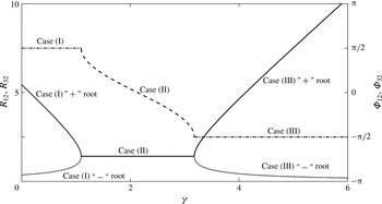
Variation of the fixed points with
 $\unicode[STIX]{x1D6FE}$
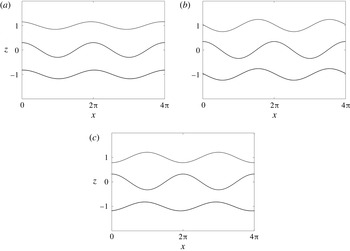
is also shown in figure 2. The derivations of Cases (I)–(III) are involved and are briefly outlined in the Appendix A. The fixed-point configurations corresponding to each case are shown in figure 3(a–c). A pair of sinuous waves correspond to Case (I); see figure 3(a). The phase-locked configuration of Case (II) is shown in figure 3(b); it corresponds to normal-mode instability and the phase shifts are dependent on
 $\unicode[STIX]{x1D6FE}$
; see (3.12b
). Case (III) reveals a pair of varicose waves as shown in figure 3(c).
In order to understand the nature of stability corresponding to each case mentioned above, we have computed the eigenvalues of the Jacobian matrix of the right-hand side of (3.7)–(3.10) evaluated at the fixed points. In Case (II), all eigenvalues always have a negative real part, implying ‘growing normal mode’ (as shown in GL14). In other words, the range of
 $\unicode[STIX]{x1D6FE}$
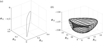
given in Case (II) allows normal-mode type instabilities. Here wave synchronization is evident – all the three waves are locked in amplitude and phase, and therefore grow at the same rate. The eigenvalues always have zero real part in Cases (I) and (III), and the fixed points appear to be unstable. Small perturbations from them lead to what appear to be periodic or pseudo-periodic orbits. As an example, for
 $\unicode[STIX]{x1D6FE}=6$
(which corresponds to Case (III) when
 $\unicode[STIX]{x1D6FC}=1$
and
 $Z=1$
), we found both periodic and pseudo-periodic orbits corresponding to different initial conditions, as shown in figure 4.
Variation of fixed points with
 $\unicode[STIX]{x1D6FE}$
for
 $\unicode[STIX]{x1D6FC}=1$
and
 $Z=1$
. Solid lines indicate
 $R_{12}$
and
 $R_{32}$
, while dashed lines indicate
 $\unicode[STIX]{x1D6F7}_{12}$
and
 $\unicode[STIX]{x1D6F7}_{32}$
.

Three interfacial waves on reaching phase-locked configuration (fixed points). (a)
 $\unicode[STIX]{x1D6FE}=1$
, which corresponds to Case (I). Amplitudes have been exaggerated. (b)
 $\unicode[STIX]{x1D6FE}=2$
, which corresponds to Case (II), which is an unstable normal mode. (c)
 $\unicode[STIX]{x1D6FE}=3.2$
, which corresponds to Case (III). Amplitudes have been exaggerated.

Behaviour around fixed points for
 $\unicode[STIX]{x1D6FE}=6$
corresponding to different initial conditions: (a) initial condition
 $(R_{12},R_{32},\unicode[STIX]{x1D6F7}_{12},\unicode[STIX]{x1D6F7}_{32})=(0.01,0.01,-\unicode[STIX]{x03C0}/4,-\unicode[STIX]{x03C0}/4)$
and (b) initial condition
 $(R_{12},R_{32},\unicode[STIX]{x1D6F7}_{12},\unicode[STIX]{x1D6F7}_{32})=(10,15,-\unicode[STIX]{x03C0}/2,-\unicode[STIX]{x03C0}/2)$
.

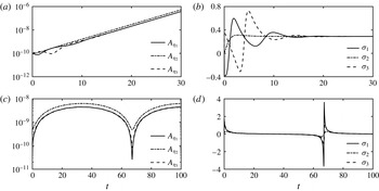
Temporal variation of amplitudes and growth rates of the constituent waves: (a) Amplitude and (b) growth rate corresponding to
 $\unicode[STIX]{x1D6FE}=3$
(Case (II)). (c) Amplitude and (d) growth rate corresponding to
 $\unicode[STIX]{x1D6FE}=3.18$
(Case (III)).

We also look at the temporal variation of amplitudes and growth rates of each constituent wave. For normal-mode instability, all the waves have the same constant
 $\unicode[STIX]{x1D70E}$
, which is possible only in Case (II) because there is only one root corresponding to
 $R_{12}$
or
 $R_{32}$
. In figure 5, we have plotted the amplitude and growth rate of each wave corresponding to
 $\unicode[STIX]{x1D6FE}=3$
and
 $3.18$
. In all our simulations
 $\unicode[STIX]{x1D6FC}=1$
and
 $Z=1$
. Hence
 $\unicode[STIX]{x1D6FE}=3$
represents Case (II) while
 $\unicode[STIX]{x1D6FE}=3.18$
represents Case (III), the latter representing behavior in the neighbourhood of the upper stability boundary (
 $\unicode[STIX]{x1D6FE}=\text{e}^{-2\unicode[STIX]{x1D6FC}Z}+2+2\sqrt{2}\text{e}^{-\unicode[STIX]{x1D6FC}Z}$
). Figure 5(a,b) shows that the constituent waves undergo transient growth/decay initially, but soon synchronize and attain the same normal-mode growth rate. In this case the initial condition is
 $(1,1,-\unicode[STIX]{x03C0},0)$
. Case (III) (as well as Case (I)) represents that part of the parameter space for which canonical normal-mode theory would predict neutral stability. As is evident from figure 5(c,d), which corresponds to an initial condition of
 $(5,5,0,\unicode[STIX]{x03C0}/4)$
, transient growth/decay is possible. In fact the waves grow by more than an order of magnitude. A growth of one or two orders of magnitude in amplitude may not be significant enough to introduce nonlinearity into the system and alter the background flow through wave-mean interactions. However, large transient growth may arise in a more general setting shown in figure 1(a), and this hypothesis needs to be tested in future.
A significant aspect of WIT is that it allows us to capture the transient dynamics of each wave separately. As shown in figure 5(b), the three waves undergo different growth rates initially. Such behavior cannot be properly captured using eigenvalue analysis (i.e. normal-mode stability theory) or singular-value decomposition (SVD) techniques (generalized stability theory) outlined in Farrell & Ioannou (Reference Farrell and Ioannou1996). While SVD analysis does capture transient growth, the growth rates of all the constituent waves have to be the same. This growth rate is given by the maximum singular value, and is known as ‘optimal growth’ in the literature. Clearly SVD analysis will not be able to predict the unequal growth/decay rates of the constituent waves during the initial period shown in figure 5(b).
We have also calculated the Lyapunov exponents numerically. Formally, the maximum Lyapunov exponent is defined as
 $$\begin{eqnarray}\displaystyle \unicode[STIX]{x1D706}_{max}\equiv \lim _{t\rightarrow \infty }\lim _{\unicode[STIX]{x1D6FF}\boldsymbol{X}_{0}\rightarrow 0}\frac{1}{t}\ln \left(\frac{|\unicode[STIX]{x1D6FF}\boldsymbol{X}(\boldsymbol{t})|}{|\unicode[STIX]{x1D6FF}\boldsymbol{X}_{0}|}\right). & & \displaystyle\end{eqnarray}$$
It characterizes the exponential rate of separation of infinitesimally close trajectories whose initial separation is
 $\unicode[STIX]{x1D6FF}\boldsymbol{X}_{0}$
. An autonomous nonlinear dynamical system with
 $\unicode[STIX]{x1D706}_{max}>0$
is non-integrable, hence chaos is a possibility (Yoshida Reference Yoshida2010). We have computed the Lyapunov exponents numerically up to
 $t=10\,000$
using the procedure outlined in Wolf et al. (Reference Wolf, Swift, Swinney and Vastano1985). For
 $\unicode[STIX]{x1D6FE}>6$
, the magnitudes of Lyapunov exponents oscillate between zero and a small positive number. It is difficult to ascertain whether they will remain positive even at very large times.
4 Conclusions and remarks
WIT has previously been studied mainly to provide a physical interpretation of shear instabilities. It turns out that, in most situations, two interfacial waves are adequate in this regard. However, there are many geophysical flows where multiple interfacial waves are present, and analysing their interactions is crucial for understanding those processes. In this regard we have formulated a generalized theory to study interactions between
 $M$
linear interfacial waves. Moreover, the approach being kinematic (i.e. no need to specify the physics of the problem in advance), it is applicable to a wide range of physical problems. By taking an expanded view of such interactions without making the commonly used normal-mode assumption, we have presented an apparently counter-intuitive phenomenon – nonlinear dynamics within the purview of linear wave theory. This phenomenon arises because the governing linear PDEs yield a nonlinear autonomous dynamical system when the Fourier ansatz is used instead of the normal-mode anzatz.
This general framework has been applied to a saw-tooth jet profile with three interfaces, yielding a 5D nonlinear dynamical system (3.1)–(3.5). For a certain range of the Froude-number-like parameter
 $\unicode[STIX]{x1D6FE}$
, the system, usually after an initial transient growth or decay, gives rise to normal-mode instabilities. If one starts with the normal-mode ansatz at the outset, one will find exponentially growing instabilities in this range of
 $\unicode[STIX]{x1D6FE}$
. Outside this range, normal-mode theory predicts neutral stability. However, in this apparently uninteresting range of
 $\unicode[STIX]{x1D6FE}$
, our more general Fourier ansatz formalism shows that transient growth in amplitude by about an order of magnitude is possible for some initial conditions. In more complicated systems it may so happen that one of the constituent waves can grow by many orders of magnitude, making the physical system nonlinear. The WIT framework enables the capture of different growth rates of the constituent waves; eigen-analysis and SVD would fail in this regard.
The range of
 $\unicode[STIX]{x1D6FE}$
for which normal-mode theory predicts neutral stability is reasonably complex. The Lyapunov exponents calculated in this range (especially when
 $\unicode[STIX]{x1D6FE}>6$
) are found to oscillate between zero and a small positive number; it is difficult to ascertain whether they will continue to do so at longer times. In a later communication we therefore intend to further explore the possibility of chaos, especially when there are more than three interacting waves. Chaos may also appear when the kinematic and/or geometric symmetry of the three-wave system is broken.
Outside the normal-mode parameter regime, nonlinearity of the 5D dynamical system stemming from the three-wave interaction problem gives rise to periodic and pseudo-periodic orbits in phase space. Fixed points bifurcate under small perturbations to exhibit periodic and pseudo-periodic behavior. This is in stark contrast to the 2D dynamical system stemming from the two-wave interaction problem, which reveals only stable and unstable nodes in the normal-mode parameter range, and no fixed points (or other interesting features) outside this range.
Acknowledgements
We are grateful to the anonymous referees for their useful comments and suggestions. A.G. thanks STC/ME/2016176 and PLANEX/PHY/2015239 for research support.
Appendix A. Derivation of the fixed points for the three-interface problem
Fixed points of the system can be found by equating the right-hand side of each of (3.7)–(3.10) to
 $0$
. Subtracting (3.7) from (3.8) and imposing
 ${\dot{R}}_{12}=0$
and
 ${\dot{R}}_{32}=0$
, we obtain the following conditions:
 $$\begin{eqnarray}\displaystyle & \displaystyle \text{either}\quad R_{12}^{2}+R_{32}^{2}=R_{12}^{2}R_{32}^{2}~(\text{Condition}~\text{I}), & \displaystyle\end{eqnarray}$$
 $$\begin{eqnarray}\displaystyle & \displaystyle \text{or}\quad R_{12}\cos \left(\unicode[STIX]{x1D6F7}_{32}\right)=-R_{32}\cos \left(\unicode[STIX]{x1D6F7}_{12}\right)~(\text{Condition}~\text{II}). & \displaystyle\end{eqnarray}$$
Furthermore, imposing
 $\dot{\unicode[STIX]{x1D6F7}}_{12}=0$
and
 $\dot{\unicode[STIX]{x1D6F7}}_{32}=0$
respectively in (3.9) and (3.10), we obtain
 $$\begin{eqnarray}\displaystyle & \displaystyle \left(\unicode[STIX]{x1D6FE}-2\right)\text{e}^{\unicode[STIX]{x1D6FC}Z}=-\frac{1+R_{12}^{2}}{R_{12}}\sin \left(\unicode[STIX]{x1D6F7}_{12}\right)-\frac{1}{R_{32}}\sin \left(\unicode[STIX]{x1D6F7}_{32}\right)+\frac{R_{12}}{R_{32}}\cos \left(\unicode[STIX]{x1D6F7}_{12}-\unicode[STIX]{x1D6F7}_{32}\right)\text{e}^{-\unicode[STIX]{x1D6FC}Z}, & \displaystyle \nonumber\\ \displaystyle & & \displaystyle\end{eqnarray}$$
 $$\begin{eqnarray}\displaystyle & \displaystyle \left(\unicode[STIX]{x1D6FE}-2\right)\text{e}^{\unicode[STIX]{x1D6FC}Z}=-\frac{1+R_{32}^{2}}{R_{32}}\sin \left(\unicode[STIX]{x1D6F7}_{32}\right)-\frac{1}{R_{12}}\sin \left(\unicode[STIX]{x1D6F7}_{12}\right)+\frac{R_{32}}{R_{12}}\cos \left(\unicode[STIX]{x1D6F7}_{12}-\unicode[STIX]{x1D6F7}_{32}\right)\text{e}^{-\unicode[STIX]{x1D6FC}Z}. & \displaystyle \nonumber\\ \displaystyle & & \displaystyle\end{eqnarray}$$
To obtain fixed points of the system given by (3.7)–(3.10), we have to consider two separate cases: (1) Case (i): (A 3)–(A 4) and Condition I, and (2) Case (ii): (A 3)–(A 4) and Condition II.
A.1 Case (i)
Condition I can be further analysed to produce
 $$\begin{eqnarray}\displaystyle R_{12}=\frac{R_{32}}{\sqrt[]{R_{32}^{2}-1}}\quad \text{and}\quad R_{32}=\frac{R_{12}}{\sqrt[]{R_{12}^{2}-1}}. & & \displaystyle\end{eqnarray}$$
Since
 $R_{12}$
and
 $R_{32}$
are real, this implies
 $R_{12}\in (1,\infty )$
as well as
 $R_{32}\in (1,\infty )$
.
Subtracting (A 3) from (A 4) we get
 $$\begin{eqnarray}\frac{1}{R_{12}}\sin \left(\unicode[STIX]{x1D6F7}_{32}\right)-\frac{1}{R_{32}}\sin \left(\unicode[STIX]{x1D6F7}_{12}\right)=\text{e}^{-\unicode[STIX]{x1D6FC}Z}\cos \left(\unicode[STIX]{x1D6F7}_{12}-\unicode[STIX]{x1D6F7}_{32}\right)\left[\left(\frac{1}{R_{12}}\right)^{2}-\left(\frac{1}{R_{32}}\right)^{2}\right].\end{eqnarray}$$
Imposing Condition I and
 ${\dot{R}}_{12}=0$
in (3.7), we obtain
 $$\begin{eqnarray}\frac{1}{R_{12}}\cos \left(\unicode[STIX]{x1D6F7}_{32}\right)-\frac{1}{R_{32}}\cos \left(\unicode[STIX]{x1D6F7}_{12}\right)=\text{e}^{-\unicode[STIX]{x1D6FC}Z}\sin \left(\unicode[STIX]{x1D6F7}_{12}-\unicode[STIX]{x1D6F7}_{32}\right).\end{eqnarray}$$
Note that imposing Condition I and
 ${\dot{R}}_{32}=0$
in (3.8) also produces (A 7). Squaring and adding (A 6) and (A 7) and using Condition I, we obtain either
Case (i 1):
 $$\begin{eqnarray}\frac{2}{R_{12}R_{32}}\cos \left(\unicode[STIX]{x1D6F7}_{12}-\unicode[STIX]{x1D6F7}_{32}\right)=1,\end{eqnarray}$$
or
Case (i 2):
 $$\begin{eqnarray}\frac{2}{R_{12}R_{32}}\cos \left(\unicode[STIX]{x1D6F7}_{12}-\unicode[STIX]{x1D6F7}_{32}\right)=\text{e}^{2\unicode[STIX]{x1D6FC}Z}-1.\end{eqnarray}$$
For Case (i 1), using Condition I produces
 $$\begin{eqnarray}R_{12}=R_{32}=\sqrt{2}\quad \text{and}\quad \unicode[STIX]{x1D6F7}_{12}=\unicode[STIX]{x1D6F7}_{32}=\sin ^{-1}\left[\frac{1}{2\sqrt{2}}\left\{\text{e}^{-\unicode[STIX]{x1D6FC}Z}-\left(\unicode[STIX]{x1D6FE}-2\right)\text{e}^{\unicode[STIX]{x1D6FC}Z}\right\}\right].\end{eqnarray}$$
For Case (i 2), using Condition I produces (after long but straightforward algebra)
 $$\begin{eqnarray}\displaystyle \left.\begin{array}{@{}c@{}}\displaystyle \text{either}~R_{12}=R_{32}=\sqrt{2}\quad \text{and}\\ \qquad \displaystyle \unicode[STIX]{x1D6F7}_{12}=\unicode[STIX]{x1D6F7}_{32}=\sin ^{-1}\left[\frac{1}{2\sqrt{2}}\left\{\text{e}^{-\unicode[STIX]{x1D6FC}Z}-\left(\unicode[STIX]{x1D6FE}-2\right)\text{e}^{\unicode[STIX]{x1D6FC}Z}\right\}\right]\\ \displaystyle \text{or}~R_{12}=R_{32}=\sqrt{2}\quad \text{and}\\ \qquad \displaystyle \unicode[STIX]{x1D6F7}_{32}=\unicode[STIX]{x03C0}-\unicode[STIX]{x1D6F7}_{12}=\sin ^{-1}\left[\frac{1}{\sqrt{2}}\left\{\text{e}^{\unicode[STIX]{x1D6FC}Z}\pm \sqrt{1+\left(\unicode[STIX]{x1D6FE}-1\right)\text{e}^{2\unicode[STIX]{x1D6FC}Z}}\right\}\right].\end{array}\right\} & & \displaystyle\end{eqnarray}$$
The Cases (i 1) and (i 2) produce (A 10)–(A 11) provided
 $$\begin{eqnarray}\displaystyle \text{e}^{-2\unicode[STIX]{x1D6FC}Z}+2-2\sqrt{2}\text{e}^{-\unicode[STIX]{x1D6FC}Z}\leqslant \unicode[STIX]{x1D6FE}\leqslant \text{e}^{-2\unicode[STIX]{x1D6FC}Z}+2+2\sqrt{2}\text{e}^{-\unicode[STIX]{x1D6FC}Z}. & & \displaystyle\end{eqnarray}$$
A.2 Case (ii)
Imposing Condition II and
 ${\dot{R}}_{12}=0$
in (3.7), we obtain
 $$\begin{eqnarray}\cos \left(\unicode[STIX]{x1D6F7}_{12}\right)\left[R_{32}\text{e}^{\unicode[STIX]{x1D6FC}Z}-\frac{R_{32}}{R_{12}}\sin \left(\unicode[STIX]{x1D6F7}_{12}\right)-\sin \left(\unicode[STIX]{x1D6F7}_{32}\right)\right]=0.\end{eqnarray}$$
Note that imposing Condition II and
 ${\dot{R}}_{32}=0$
in (3.8) also produces (A 13). From (A 13) and Condition II we get either
Case (ii 1):
 $$\begin{eqnarray}\cos \left(\unicode[STIX]{x1D6F7}_{12}\right)=0\quad \text{and}\quad \cos \left(\unicode[STIX]{x1D6F7}_{32}\right)=0,\quad \text{hence}~\unicode[STIX]{x1D6F7}_{12}=\pm \frac{\unicode[STIX]{x03C0}}{2}~\text{and}~\unicode[STIX]{x1D6F7}_{32}=\pm \frac{\unicode[STIX]{x03C0}}{2},\end{eqnarray}$$
or
Case (ii 2):
 $$\begin{eqnarray}\sin \left(\unicode[STIX]{x1D6F7}_{32}\right)=R_{32}\text{e}^{\unicode[STIX]{x1D6FC}Z}-\frac{R_{32}}{R_{12}}\sin \left(\unicode[STIX]{x1D6F7}_{12}\right).\end{eqnarray}$$
Case (ii 1) can be divided into four subcases.
Case (ii 1.1):
 $\unicode[STIX]{x1D6F7}_{12}=\unicode[STIX]{x03C0}/2,\unicode[STIX]{x1D6F7}_{32}=\unicode[STIX]{x03C0}/2$
.
Subtracting (A 3) from (A 4) we obtain
 $$\begin{eqnarray}\text{(I)}~R_{12}=\frac{R_{32}\text{e}^{-\unicode[STIX]{x1D6FC}Z}}{R_{32}-\text{e}^{-\unicode[STIX]{x1D6FC}Z}},\quad \text{or}\quad \text{(II)}~R_{12}=R_{32}.\end{eqnarray}$$
When (I) holds, we find
 $\unicode[STIX]{x1D6FE}=1-\text{e}^{-2\unicode[STIX]{x1D6FC}Z}$
. When (II) holds,
 $R_{12}$
and
 $R_{32}$
can be directly expressed in terms of
 $\unicode[STIX]{x1D6FE}$
and
 $\text{e}^{\unicode[STIX]{x1D6FC}Z}$
:
 $$\begin{eqnarray}R_{12}=R_{32}={\textstyle \frac{1}{2}}\left[\text{e}^{\unicode[STIX]{x1D6FC}Z}\left(\text{e}^{-2\unicode[STIX]{x1D6FC}Z}+2-\unicode[STIX]{x1D6FE}\right)\pm \sqrt{\text{e}^{2\unicode[STIX]{x1D6FC}Z}\left(\text{e}^{-2\unicode[STIX]{x1D6FC}Z}+2-\unicode[STIX]{x1D6FE}\right)^{2}-8}\right],\end{eqnarray}$$
provided
 $$\begin{eqnarray}\displaystyle \unicode[STIX]{x1D6FE}\leqslant \text{e}^{-2\unicode[STIX]{x1D6FC}Z}+2-2\sqrt{2}\text{e}^{-\unicode[STIX]{x1D6FC}Z}. & & \displaystyle\end{eqnarray}$$
This basically implies that
 $R_{12}$
and
 $R_{32}$
must be real, i.e. the discriminant of (A 17) is non-negative.
Case (ii 1.2):
 $\unicode[STIX]{x1D6F7}_{12}=\unicode[STIX]{x03C0}/2,\unicode[STIX]{x1D6F7}_{32}=-(\unicode[STIX]{x03C0}/2)$
.
Subtracting (A 3) from (A 4) we obtain
 $$\begin{eqnarray}R_{12}=\frac{R_{32}\text{e}^{-\unicode[STIX]{x1D6FC}Z}}{R_{32}+\text{e}^{-\unicode[STIX]{x1D6FC}Z}}\quad \text{and}\quad \unicode[STIX]{x1D6FE}=1-\text{e}^{-2\unicode[STIX]{x1D6FC}Z}.\end{eqnarray}$$
Case (ii 1.3):
 $\unicode[STIX]{x1D6F7}_{12}=-(\unicode[STIX]{x03C0}/2),\unicode[STIX]{x1D6F7}_{32}=\unicode[STIX]{x03C0}/2$
.
Subtracting (A 3) from (A 4) we obtain
 $$\begin{eqnarray}R_{32}=\frac{R_{12}\text{e}^{-\unicode[STIX]{x1D6FC}Z}}{R_{12}+\text{e}^{-\unicode[STIX]{x1D6FC}Z}}\quad \text{and}\quad \unicode[STIX]{x1D6FE}=1-\text{e}^{-2\unicode[STIX]{x1D6FC}Z}.\end{eqnarray}$$
Case (ii 1.4):
 $\unicode[STIX]{x1D6F7}_{12}=-(\unicode[STIX]{x03C0}/2),\unicode[STIX]{x1D6F7}_{32}=-(\unicode[STIX]{x03C0}/2)$
.
 $$\begin{eqnarray}R_{12}=R_{32}={\textstyle \frac{1}{2}}\left[-\text{e}^{\unicode[STIX]{x1D6FC}Z}\left(\text{e}^{-2\unicode[STIX]{x1D6FC}Z}+2-\unicode[STIX]{x1D6FE}\right)\pm \sqrt{\text{e}^{2\unicode[STIX]{x1D6FC}Z}\left(\unicode[STIX]{x1D6FE}-2-\text{e}^{-2\unicode[STIX]{x1D6FC}Z}\right)^{2}-8}\right],\end{eqnarray}$$
provided
 $$\begin{eqnarray}\displaystyle \unicode[STIX]{x1D6FE}\geqslant \text{e}^{-2\unicode[STIX]{x1D6FC}Z}+2+2\sqrt{2}\text{e}^{-\unicode[STIX]{x1D6FC}Z}. & & \displaystyle\end{eqnarray}$$
Like Case (ii 1.1), Case (ii 1.4) is also valid when
 $R_{12}$
and
 $R_{32}$
are real, i.e. the discriminant of (A 21) is non-negative.
Case (ii 2):
 $\sin (\unicode[STIX]{x1D6F7}_{32})=R_{32}\text{e}^{\unicode[STIX]{x1D6FC}Z}-(R_{32}/R_{12})\sin (\unicode[STIX]{x1D6F7}_{12})$
.
This condition, along with Condition II when substituted in (A 3), produces
 $\unicode[STIX]{x1D6FE}=1-\text{e}^{-2\unicode[STIX]{x1D6FC}Z}$
.
In summary, from Conditions I and II and Cases (i) and (ii), we obtain (3.11)–(3.13), provided we ignore the singular case when
 $\unicode[STIX]{x1D6FE}=1-\text{e}^{-2\unicode[STIX]{x1D6FC}Z}$
. This particular case is interesting in its own right and will be addressed in a future communication.