


I. INTRODUCTION
An intense research activity is currently being devoted to the development of technologies allowing low-power devices, possibly wearable or implantable to operate with no need for battery feed. This may be accomplished by extracting the required power from many sources that are present in the environment, such as propagating radio waves, sunlight or vibrations. Devices powered by radio waves have been widely used in passive radio identification (RFID) [Reference Rizzoli, Costanzo, Rubini and Masotti1]. In this case, battery-free transceivers (tags) extract the power needed to turn on the active devices from the field radiated by a reader of known position. The received field is usually narrow band, of medium intensity, and has known polarization and direction of arrival [Reference Curty, Joehl, Dehollain and Declercq2]. The goal is to provide a rectified DC voltage to bias the active devices, irrespective of the received power level. Different design configurations of charge-pump voltage multipliers have been proposed in recent years [Reference Shinohara and Matsumoto3], based on both Schottky diodes and CMOS technology. In almost all the realizations reported, the power conversion efficiency is rather poor. One of the main purposes of our work is to show that this is primarily due to the lack of an adequate system simulation approach. Section II of the paper tries to bridge this gap. We start from the realization that the true receiver input is the radiated field incident on the receiver antenna, from which the circuit excitation of the receiver can be exactly derived by electromagnetic (EM) theory. The rectified power may then be accurately computed by a full nonlinear analysis of the receiver including the antenna described by EM simulation. In this way, we can define an overall figure of merit, conventionally called the EM conversion efficiency, which can be successfully used as the design goal of a comprehensive system optimization.
The work on RF power scavenging and rectification reported until now has been mostly dedicated to narrow-band (essentially single-frequency) incident microwave radiation with relatively high power densities [Reference Shinohara and Matsumoto3]. For validation purposes, in sections III.A and III.B our design approach is first applied to these kinds of circuit–antenna assemblies in ultra-low power budget conditions. In more general, RF harvesting applications, frequency, position, and polarization of the source may not be a priori known. In such cases, the antenna and rectifier design are much more complex, so that the use of an integrated design platform of the kind presented in this paper becomes even more critical. To address this kind of application, in section III C, we propose a novel-integrated antenna consisting of a suitable combination of resonant patches for multi-frequency harvesting purposes [Reference Rizzoli, Bichicchi, Costanzo, Donzelli and Masotti4]. This solution is shown to offer significant advantages with respect to a broadband one [Reference Hagerty5], because it allows the conversion efficiency to be effectively maximized at those operating frequencies where RF sources are most likely to be present. We show that a nonlinear/EM co-design of the entire rectenna based on the ideas introduced in section II may be simultaneously carried out at all frequencies of interest, to achieve the best trade-off among possible incident power levels and frequency values. This overcomes simplifying assumptions based on lumped-element equivalent circuit approaches [Reference Douyere, Lan Sun Luk and Alicalapa6]. In the latter case, a lumped-element equivalent circuit needs to be generated for each harvesting frequency and related harmonics.
II. COUPLED NUMERICAL AND FIELD-THEORETICAL RECTENNA DESIGN
The RF harvesting scenario we refer to is depicted in Fig. 1. Several RF sources may exist and are described in terms of their respective radiated fields incident on the rectenna. The frequency, direction of arrival, and polarization of each incident field may be arbitrary. Assuming that the RF sources are located in the far-field region of the harvester, a kth incident field at the harvester location may be described as a uniform plane wave and thus by a constant complex vector Einck.
General scenario of a rectenna in the presence of several radiating sources.

For each source, we use the reciprocity theorem to exactly compute the RF excitation of the rectifier circuit. For this purpose, two EM configurations of the harvester antenna, labelled “a” and “b” in Fig. 2, are considered, corresponding to the receiving and transmitting modes of operation, respectively. The corresponding equivalent circuits are also shown in Fig. 2.
Situations “a” and “b” considered for the application of the reciprocity theorem.

Let us denote by EA(r, θ, ϕ, ω) the far field radiated by the harvesting antenna operating in the transmitting mode when powered by a voltage source of known amplitude U, internal resistance R 0, and angular frequency ω, as in Fig. 2b. r, θ, ϕ are spherical coordinates in a reference frame having origin in the antenna phase center O 1. We may write

where the normalized field eA does not depend on the distance r or on the source voltage U. It is now possible to rigorously compute the Norton current source equivalent to the kth RF incident field. Indeed, by a straightforward application of the reciprocity theorem, we obtain
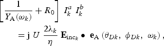
where θDk, ϕDk define the direction of arrival of the field radiated by the kth environmental RF source, ωk is its angular frequency, and η is the free-space wave impedance. Y A(ω) is the frequency-dependent antenna admittance computed by EM analysis. From (1) and Fig. 2, we obtain

Taking advantage of the linearity of the excitation mechanism, the contributions of all ambient sources may be simply combined in the way shown in Fig. 3 to give a comprehensive circuit description of the rectifier excitation.
Norton equivalent circuit of the rectenna system under multiple excitations.

Since the rectifying circuit is passive, due to energy conservation in the circuit depicted in Fig. 3, the power actually delivered to the load cannot exceed the sum of the maximum powers that can be delivered by the individual current sources under a conjugate match, which is given by
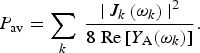
The theoretical upper bound established by (4) will be referred to in the following as the RF available power and will be used as a reference for the definition of the system efficiency. On the other hand, in order to correctly compute the rectified power, the circuit must be analyzed by nonlinear techniques such as harmonic balance, as a nonlinear circuit under multitone excitation. The electrical regime has a discrete spectrum with spectral lines located at all the intermodulation products of the exciting fundamental frequencies ωk up to a prescribed order. After performing such an analysis by well-established algorithms [Reference Rizzoli, Costanzo, Masotti, Lipparini and Mastri7, Reference Rizzoli, Costanzo, Masotti and Spadoni8], the DC power P out actually delivered to the load is known, so that the EM conversion efficiency can be rigorously defined as

This makes it possible to define simultaneous design goals on the conversion efficiency across the frequency bands of interest for the actual power levels pertaining to different wireless standards [Reference Rizzoli, Costanzo, Masotti and Spadoni8]. In this way, several crucial phenomena, such as power mismatch between antenna and receiver front end, polarization conflicts between incident electric fields and harvester antenna, and the simultaneous presence of different RF sources, are automatically included in all the evaluations. An important step of the design procedure is the selection of the rectifier topology, which is crucial for ultra-low power budgets. One degree of freedom is the number of stages. Our choice, in agreement with [Reference Essel, Brenk, Heidrich and Weigel9], is a single-stage full-wave peak-to-peak RF-DC power converter. For the sake of clarity, a possible layout of the blocks appearing in Fig. 3 is shown in Fig. 4 together with the rectifier topology.
Rectenna layout and rectifier topology.

The selection of a proper Schottky diode plays an essential role. The primary objective is to make use of devices whose turn-on is guaranteed at ultra-low incident power levels. In addition, in order to obtain a good conversion efficiency, the lowest possible zero-bias junction capacitance (C j0) and the highest saturation current (I S) are required. Table 1 lists the Spice equivalent circuit parameters of several diodes available from the market.
Diode parameters comparison.

The last row of the table refers to the estimated conversion efficiency of a reference one-stage full-wave rectifier powered by a 1.38 dBm source with 50 Ω input and load impedances. The best efficiency reported in this line has led to the choice of the Skyworks SMS7630 diode. A diode package model has also been included in the rectenna design and its accuracy has been experimentally tested.
In the rectenna design problems addressed in the next section, we take into account four harmonics plus DC for the single-frequency design, and intermodulation products up to the fourth order for the multi-source design. In this way, the rectification of higher-order harmonics generated by the nonlinearities may be investigated, as well. The optimum load providing the best trade-off among the possible operating frequencies and power levels is also determined by the same design procedure.
III. RECTENNA OPTIMIZATION AND RESULTS
The design of RF harvesters both for known and unknown RF link properties (θDk, ϕDk, ωk) is described in this section. In the former case, the RF source is located in a specific position and operates over a known frequency band so that the harvester can be placed in the maximum radiation direction; in the latter, either the RF source location or the (possibly wearable) harvester orientation are a priori unknown. Of course, the main difference among these situations concerns the radiating element design. With increasing complexity of the problem, the following cases can be encountered. (a) A single and completely defined (both location and frequency) RF source is available: the antenna must have high gain and its direction of maximum gain and polarization must match those of the source. (b) The RF source band is fixed, but its location is not: the harvester antenna must have a circular polarization (CP) in the band of interest and low directivity. (c) RF sources radiating in several frequency bands and ubiquitously distributed exist: the antenna should be circularly polarized and either very broadband or a combination of resonant antennas, each one designed for a specific application-dependent frequency band.
A) Harvesting from single-frequency single source
A first design addresses a highly efficient RF harvester operating in the UMTS (Universal Mobile Telecommunication System)/GSM1800 (Global System for Mobile Communication) band. The photograph and dimensions of the entire system layout are shown in Fig. 5. A high gain (13 dB) linearly polarized four-patch array on a Rogers Duroid 5870 substrate has been designed together with the rectifier matching network and the load, to best perform at the RF power levels that are typically available during a single phone call.
Photograph of a harvester prototype based on a 2 × 2 linearly polarized patch antenna array (overall dimensions: 22 × 19 cm2).

Fig. 6 shows the computed rectenna performance at one frequency within the UMTS band before and after optimization: an EM conversion efficiency better than 50% is obtained as P av exceeds 100 µW. Fig. 7 shows that the achievable optimum efficiency is frequency-dependent, mostly because of the frequency dispersive properties of the antenna. In order to validate these results, the harvester is positioned in front of a cell phone and the open-circuit voltage at the load terminals is recorded during a transmission burst (which lasts approximately 500 µs) at several distances from the source. Fig. 8 shows the comparison between these measurements and the results computed by our system analysis procedure. An excellent agreement is observed down to 50 cm distance between the cell phone and the harvester. At lower distances the predicted DC voltage begins to overestimate the measurements. This is believed to be due to failure of the uniform plane wave approximation used to compute (2) at such short distances. In order to overcome this problem, work is currently in progress to replace (2) with a more rigorous and general formula for the computation of the equivalent current sources.
Starting point and optimized electromagnetic conversion efficiency of the 2 × 2 patch harvester at 1.95 GHz.

Frequency dependence of the optimum EM conversion efficiency at very low power levels.

Predicted and measured DC output voltage of the 2 × 2 patch harvester produced by a cell phone transmitting from different distances.

B) Harvesting from single-frequency multiple sources
A second design has been focused on harvesting from multiple sources operating in the GSM1800 band. A coplanar slot antenna with a gain of about 2 dB has been used: CP is achieved by protruding a T-shaped metallic strip from the ground plane towards the slot center [Reference Sze, Wong and Huang10]. A photograph of the rectenna prototype is shown in Fig. 9. The optimized EM conversion efficiency is plotted in Fig. 10 versus P av for several operating frequencies inside the GSM band. The dispersive behavior of the antenna is again responsible for the efficiency spread across the operating band. Fig. 11 provides a comparison between the measured and predicted DC output power as a function of the measured incident power density at several operating frequencies.
Photograph of the harvester prototype based on a coplanar-slot circularly polarized antenna (overall dimensions: 9 × 11 cm2).

Frequency dependence of the EM conversion efficiency at low power levels for the circularly polarized harvester.

Computed and measured DC output power for the circularly polarized harvester.

Fig. 12 underlines the impact of the receiving antenna polarization. In this figure, the rectified output power is plotted for several directions of incidence under the assumption that the incident field Einc1 is linearly polarized. The direction of polarization of Einc1 is defined as follows:

Output DC power of the linearly (a) and circularly (b) polarized harvester for several directions of arrival of a linearly polarized incident RF field.

Referring to Fig. 1, in (6)  are the unit vectors of the θ, ϕ coordinate directions,
 are the unit vectors of the x, y directions, and ψ1 is the angle between the incident field direction of polarization and the
 direction (for θD ≠ 0) or the x-direction (for θD = 0). The receiving antenna is oriented in such a way that its broadside direction (θ = 0) is parallel to the ground, and its position is held fixed. Figure 12a shows the results obtained for a rectenna linearly polarized in the vertical direction, which is chosen to coincide with the y-axis (see Fig. 1). For θD = 0, ψ1 = 90° the rectified DC power is highest due to the perfect polarization match between incident field and rectenna. However, the harvested power rapidly drops as the polarization mismatch increases. On the contrary, the rectified power in case of a circularly polarized rectenna (Fig. 12b) is almost independent of the direction of arrival.
C) Harvesting from multi-frequency sources
A more challenging RF energy scavenging system will now be considered. In order to be useful in typical humanized environments the system is required to simultaneously handle several RF incident fields, such as those radiated by cellular systems and WiFi equipment. Such sources have unknown and extremely variable power budgets, mainly due to an unpredictable distance between the harvester and the transmitting antennas. Even the operating frequency may be arbitrarily allocated within a specified range, according to multiple-access policies and traffic block probability. In this sense, multi-band performance and CP should be considered as almost compulsory requirements for a high-quality antenna operating over the bands of interest. In view of a wearable realization, the additional need for good integration properties, robustness, and minimum thickness, led to the choice of a multilayer aperture-coupled printed antenna. One advantage of this solution is a full decoupling between the rectifier and the receiving antenna. This allows the use of different kinds of substrates, each suitable for different purposes, specifically, circuit miniaturization and radiation efficiency. The antenna layout and its feeding circuitry in the multilayer arrangement, together with the top and bottom view of the prototype, are shown in Fig. 13 and are described top-down in the following. A three-band operation is achieved by exploiting the three structures on the top layer, i.e. the inner circular patch and the two outer rings, and the near-field coupling among them. The basic design idea is to have one circular resonating patch for each operating band. At the highest frequency, the inner patch is active; in the intermediate frequency band, the active patch is obtained by coupling the inner patch with the inner ring; at the lowest frequency, the three structures make up an approximately circular resonating patch. For each frequency band, the metallization not belonging to the resonant structure plays the role of a parasitic element and must be accounted for during the design process in order to check that it does not significantly affect the current distribution on the active patch or its radiating properties. To achieve this goal, the radius of the circular patch and those of the inner and outer rings are optimized together with the inter-element gaps by means of EM simulation all over the bands of interest.
Exploded layout of the multi-layer, multi-resonator rectenna (a), photograph of the multi-resonator layer (b), and of the rectifier layer (c) (overall dimensions: 14 × 13 × 1.3 cm3).

On the ground plane of the circular patches (the slotted ground in Fig. 13), two identical sets of three slots are etched to aperture-couple, the bottom layer to the radiating patches. The two sets are orthogonal to each other in order to provide the antenna CP. The slot dimensions and relative positions are designed to simultaneously provide the tightest coupling and the smallest back radiation in each band of interest. This radiating structure, only a portion of which is active in each specific frequency band, may be conceptually related to the basic design concept of log-periodic antennas. Two orthogonal modes are excited by two symmetrical microstrip feed lines, printed on the Taconic substrate (Fig. 13). These lines depart from a 90° hybrid coupler whose topology, derived from [11], has been optimized to ensure acceptable return loss, equal power division between the output ports, and constant phase difference between the output ports over each frequency band of interest. The annular rings have outer radii of 57 and 41 mm, respectively, while the circular central patch has a 30-mm radius. The coupling gap width is 0.5 mm. The three resonant slots obey the well-known relationship between working frequencies and physical lengths. Their 2D sizes are 2.8 × 28, 3 × 38, and 5.5 × 65 mm2, respectively, in order to approximately preserve a 1/10 ratio between length and width. The total thickness of the rectenna is approximately 1.3 cm. The dielectric supporting the patches consists of a 4 mm thick polyurethanic foam (εr = 1.25, tanδ = 0.0012). The 0.635 mm thick feeding circuit substrate under the ground plane is a Taconic RF-60 (εr = 6.15, tanδ = 0.0028). The bottom of the whole assembly is shielded by a ground plane separated from the feeding circuit by an 8-mm-thick foam layer. Such shielding guarantees the isolation of the harvester in view of wearable applications. The simulated amplitude of the reflection coefficient at the antenna port is plotted in Fig. 14(a): a reflection better than −10 dB is observed across each frequency band of interest. A broadband design of the antenna-rectifier matching network has been carried out together with the other design parameters described above; the measured and modeled reflection coefficients of the matched multi-resonator antenna are plotted in Fig. 14(b).
Reflection coefficient of the stand-alone antenna (a) and of the antenna matched to the rectifier (b).

The normalized co-polarized and cross-polarized radiation patterns in the x–z-plane at the center frequencies of each band are plotted in Fig. 15 showing good CP performance. An axial ratio better than 4 dB has been obtained all over the related bands. Similar behaviors are obtained for the y–z-plane and are not reported here for the sake of brevity.
Antenna normalized radiation patterns in x–z-plane: (a) 900 MHz, (b) 1.76 GHz, and (c) 2.45 GHz.

The antenna directivity is roughly constant (3.6 dB, 2.3 dB, and 3.4 dB, in the GSM900, GSM1800, and WiFi bands, respectively), which implies that the effective area is strongly dependent on frequency, as shown in Fig. 16. As a consequence, the incident field power density that is required in order to produce a constant RF available power is strongly frequency dependent, as well. These power densities are also reported in Fig. 16 for P av = 500 µW at the center frequency of each band of interest.
Incident power densities required to provide a 500 µW RF available power and effective area at each operating frequency.

The design of the whole rectenna is carried out for a [−16 dBm +8 dBm] RF available power range. The large upper bound is chosen in order to guarantee that the rectenna can handle high power levels, which may be encountered in some practical cases, e.g. when it is placed in the close proximity of a radio base station. This choice corresponds to a maximum incident field intensity of 20 V/m. The load resistance R L that plays a crucial role in achieving the best conversion efficiency is determined inside the same procedure. It is worth noting that R L = 6.3 kΩ – the optimal value in this case – is meant to be comprehensive of the whole load. A new dynamic-switching conversion scheme based on active control for harvesting energy has been developed and is discussed in detail elsewhere [Reference Costanzo, Fabiani, Romani, Masotti and Rizzoli12].
The optimization results are summarized in Fig. 17, where the converted DC power is plotted against the incident power density and the corresponding available RF power. Efficiency is better than 60% at the center frequency of each band.
Harvested power versus incident power density and RF available power: (a) in the GSM900 band, (b) in the GSM1800 band, and (c) in the WiFi band.

The integrated procedure developed in this paper allows the harvesting capabilities under multi-source excitation to be accurately evaluated. Some results are plotted in Fig. 18 for three possible combinations of RF available powers in the three frequency bands. A comparison with the results of Fig. 17 puts into evidence the usefulness of our approach. Indeed, three-tone excitation determines a frequency spectrum with intermodulation products whose effects cannot be a priori established, and the multi-source operation cannot be simply predicted as a superposition of three single-tone ones. Furthermore, the complex frequency dependence of the antenna impedance is directly accounted for in this way.
Actual harvested power in the simultaneous presence of three RF sources for several combinations of RF available power levels.

Finally, the multi-source RF harvesting design procedure has been validated by measuring its performance at ultra-low incident power densities. Fig. 19(a) and 19(b) compare the predicted and measured DC output power when harvesting from a GSM900 and a WiFi source, respectively.
Measured and simulated converted DC power at (a) 900 MHz and (b) 2450 MHz.

IV. CONCLUSIONS
In this paper, we have introduced an integrated numerical approach to the design of single- and multi-band RF power harvesters based on modern non-linear analysis techniques coupled with full-wave EM analysis. The key aspect of our method is that the receiving antenna is described by an exact Norton equivalent circuit consisting of the antenna admittance computed by EM simulation, connected in parallel with a current source evaluated by the reciprocity theorem. This avoids the use of roughly approximate lumped equivalent circuits which are normally unable to describe the antenna performance over broad frequency bands. On the contrary, the new technique allows the antenna–rectifier assembly to be accurately analyzed by non-linear CAD techniques such as multi-tone harmonic balance. This is the only way to rigorously account for the generation of harmonics or intermodulation products in the rectifier nonlinearities, which is particularly relevant in case of simultaneous harvesting from different environmental sources. In addition, this leads in a systematic way to the determination of the optimum supply and load conditions, which is essential when dealing with extremely low power budgets. The procedure has been successfully applied to the design of a number of systems harvesting RF energy from humanized environments. The final goal is to investigate the feasibility of energy-autonomous applications such as sensor nodes or RFID tags that may require power consumption few times per day during readout operation.
 Vittorio Rizzoli (M'79–SM'90–F'94) joined the University of Bologna as a Full Professor of electromagnetic fields in 1980. His research interests are in the areas of nonlinear microwave circuit simulation and design (with emphasis on modern CAD techniques for large-size problems), empirical device modeling, and electromagnetic design of integrated circuits. He is the author or co-author of over 200 technical papers on electromagnetic propagation, signal and noise analysis of microwave integrated subsystems, and related topics.
Professor Rizzoli is a member of the Editorial Board of IEEE Microwave and Wireless Components Letters, and of John Wiley's International Journal of RF and Microwave Computer Aided Engineering. He is also a member of the Paper Review Board of “Electronics Letters”. From 1987 to 1995 he has been on the Technical Program Committee of the European Microwave Conference. In 1990/92, he served as the Distinguished Microwave Lecturer of IEEE MTT-S for Region 8, lecturing in Europe, USA and the Middle East on “Simulation and Design of Nonlinear Microwave Circuits”. In 1994, he was elected Fellow of the IEEE with the citation “For Contributions to the Simulation and Design of Nonlinear Microwave Integrated Circuits”. In 1995, he served as Chairman of the 25th European Microwave Conference that was held in Bologna, Italy, in conjunction with the Celebrations for the First Centenary of the Invention of the Radio. In 1995/96, he served as Chairman of the Management Committee of the European Microwave Conference. Since 1993, he has been a member of the Technical Committee IEEE MTT-1 on Computer-Aided Design. Since 1999, he has been a member of the Technical Program Committee of the IEEE MTT-S International Microwave Symposium. In 2005/2006, he served as an Associate Editor for the IEEE Transactions on Microwave Theory and Techniques.
 Alessandra Costanzo (M'98) received the Dr. Ing. degree in electronic engineering from the University of Bologna, Bologna, Italy, in 1987.
In 1989, she joined the University of Bologna as a Research Associate. Since 2001, she has served as an Associate Professor of electromagnetic fields at the University of Bologna, Polo di Cesena. Her teaching and research activities have focused on several topics, including electrical and thermal characterization and modeling of nonlinear devices and simulation and design of active microwave-integrated circuits. She has also been devoted to the development of software tools for the broadband design of autonomous circuits and systems for electrical, stability, and noise performance. Most recently, she has worked on the development of algorithms for the analysis of self-oscillating circuits and systems excited by digitally modulated signals and for the broadband design of self-oscillating integrated antennas based on electromagnetic analysis. She is currently involved in research activities concerning the development of miniaturized transceivers for microwave RF-ID applications and RF harvesting.
Dr. Costanzo was a member of the Technical Program Committee of the European Microwave Conference from 1995 to 1997. She is also member of the IEEE and of the T-MTT, and the T-CAS Editorial Review Board. She is the reviewer of many international journals.
 Diego Masotti (M'99) received the Dr. Ing. degree in electronic engineering and Ph.D. degree in electric engineering, from the University of Bologna, Bologna, Italy, in 1990 and 1997, respectively.
In October 1998, he joined the Department of Electronics Computer Science and Systems of the University of Bologna as a Research Associate of electromagnetic fields. He is responsible of the course Design of Radiofrequency Circuits, since 2003. His research interests are in the areas of nonlinear microwave circuit simulation and design (with emphasis on modern CAD techniques for large-size problems), empirical device modeling, and electromagnetic design of integrated circuits.
Dr. Masotti is a member of the Paper Review Board of the IEEE Transaction on Microwave Theory and Techniques since 2004. He was the recipient of a 1991 research grant issued by Fondazione G. Marconi, Pontecchio Marconi, Italy and Alenia S.p.A., Rome, Italy.
 Francesco Donzelli received the Dr. Ing degree in Telecommunication Engineering from the University of Bologna, Italy in 2007.
He is currently pursuing the Ph.D. degree in Telecommunication Engineering at the same institute. His current research interests focus on the characterization of RF links by the combination of nonlinear, electromagnetic and propagation analysis techniques, but comprise also the project and realization of low-power rectennas for energy harvesting from wireless sources; design and analysis of RF microelectromechanical devices. Dr. Donzelli has co-authored several international papers. Presently, he is working at the Microtechnology Department of VTT Technical Research Centre of Finland (Espoo), where he has been developing RF and millimeter-wave identification tags and receivers.



