1. INTRODUCTION
Non-GPS personnel tracking systems often use gyros, either stand-alone or as parts of Inertial Measurement Units (IMUs), to estimate changes in the user's heading. Since gyros measure rate of rotation, they require, among other mathematical processing, that their signals be numerically integrated to produce the desired heading information. The numeric integration has a tendency to cause errors due to drift. Drift is produced when small, near-constant deviations from the correct signal are integrated with respect to time. The highly undesirable result of drift is that the error of the computed heading increases continuously and without bound. One can conceptually view drift as being comprised of two components: a slowly changing, near-DC component, called bias instability, and a high-frequency noise component with an average of zero called Angle Random Walk (ARW). The high-frequency component creates only relatively small errors in the computation of heading from the gyro's rate of turn measurements, since its average is about zero. In the context of this paper, we are therefore concerned only with the near-DC component of drift.
Gyros are also sensitive to changes in temperature, and certain gyros are sensitive to linear accelerations. In our application, these two effects also produce errors that can be treated as having near-DC, slow changing components, as drift does. Our proposed drift reduction method counteracts all near-DC errors regardless of whether they are caused by the physical phenomena of drift, temperature sensitivity, or sensitivity to accelerations. For that reason, throughout this paper we lump all three of these near-DC error sources together and call them collectively drift.
Before explaining our proposed drift reduction method in Section 2, we discuss here briefly several other approaches to reducing drift. The most common methods for reducing the effects of gyro drift are to integrate INS and GPS information (Cavallo et al., Reference Cavallo, Sabatini and Genovese2005), (Mohinder et al., Reference Mohinder, Lawrence and Angus2002), and (Grejner-Brzezinska et al., Reference Grejner-Brzezinska, Toth, Moafipoor, Jwa and Kwon2006). Cho et al. (Reference Cho, Lee, Park and Lee2003) integrate data from a magnetic compass as well. Basnayake et al. (Reference Basnayake, Mezentsev, Lachapelle and Cannon2005) propose a method that makes use of available maps and uses map matching techniques for further enhancement. The main drawback of these approaches is that either they require external references or information ahead of time, which may not be available all the time. For example, GPS only works outdoors and magnetic fields are often disturbed and unusable in man-made structures.
There are a few methods that do not require external references. Instead they try to find a mathematical model. A few methods attempt to find a mathematical model for bias errors (Pandit and Zang, Reference Pandit and Zang1986) and (Chen, Reference Chen2004), however these techniques have limited applicability and can only estimate the deterministic part, if any, of the bias drift.
Our proposed method, called Heuristic Drift Reduction (HDR), makes use of the fact that many of the environments in which GPS and magnetometers are ineffective (e.g., inside man-made structures) have straight-line features. For example, most corridors in buildings are straight and so are most walls and sidewalks alongside which a person might walk. At any moment, the HDR method estimates the likelihood that the user is walking along a straight line. If that likelihood is high, HDR applies a correction to the gyro output that would result in a reduction of drift if indeed the user was walking along a straight line. If the algorithm assesses that the user is not walking along a straight line, then HDR does nothing. This way, and on an abstract level, HDR uses landmarks (i.e., man-made straight-line features), but there is no requirement that the location of these landmarks be known in advance.
HDR works generally with any personnel tracking system that uses one or more gyros for measuring rate of yaw to compute the user's heading. One such personnel tracking system is the so-called Personal Dead Reckoning (PDR) system that our group developed in earlier work. However, the focus of this paper is not on our PDR system itself. For that reason and in order to avoid distraction from the general applicability of the proposed heuristic drift reduction method, we defer a description of our PDR system to Section 4.
The remainder of this paper is organized as follows. Section 2 explains the basic HDR method in the context of ideal conditions. Section 3 discusses how real conditions differ from ideal conditions, and provides several enhancements to the HDR algorithm to help cope with real conditions. Section 4 provides a description of our PDR system and Section 5 shows experimental results obtained with HDR applied to the data from our PDR system. Conclusions are presented in Section 6.
2. HEURISTIC DRIFT REDUCTION
Suppose a person is walking straight forward. Moving straight forward, the output of the z-axes gyro (i.e., the one that measures the change in heading when travelling on flat, horizontal ground) should be exactly zero throughout the trip. However, due to drift the actual output is off by some small value ε. Suppose further that we divide the total travel distance into smaller intervals. A natural choice for the length of an interval in the PDR application is from footfall to footfall. We define footfall as a single instance in which the ball of the IMU-equipped foot is fully in contact with the ground and the velocity of the sole of the user's shoe is zero. Thus, a footfall is an instance within a time period called midstance in the analysis of human walking gait [Ayyappa, Reference Ayyappa1997]. Since only one foot is instrumented, there are two steps between footfalls.
Due to the drift error ε, in each interval the rate of rotation computed based on the z-axis gyro is:

where:
ωrawRate of rotation measurement. This is the direct output of the gyro.
ωtrueTrue rate of rotation. In reality ωtrue is not known or measured, but in our idealized straight-line example ωtrue=0.
ε0Static bias drift, measured immediately prior to a walk.
εdBias drift. This is the difference between the static bias drift ε0 and the unknown near-DC drift component.
Immediately prior to each walk and with the gyro held completely motionless, the static bias drift ε0 is measured by averaging T bias seconds worth of gyro data. The value for T bias depends on the quality of the gyro and can be estimated by using the Allan Variance analysis [IEEE Standards, 1996]. T bias is also called bias time. For the IMU in our system, T bias=30 seconds.
During the walk, ε0 is subtracted from every reading of ωraw:

Then, the new heading ψi is computed:

where:
ψiComputed heading at footfall i, in [°].
T iDuration of time interval i [sec]. T i is the time between footfall i−1 and footfall i.
If εd is positive, then the change of heading is counter-clockwise (we will call it a left turn, for simplicity) and if εd is negative, then the change of heading is clockwise or a right turn. It is unpredictable whether εd will be positive or negative and εd may change signs during a walk. However, if εd changed signs very often during a walk, then drift errors will partially cancel each other out and the resulting overall heading error is less severe. Our greater concern is thus for cases where εd keeps the same sign for prolonged periods of time and thereby accrues heading errors in the same direction. For the sake of simplicity, we assume in the remainder of this section that εd keeps the same sign throughout the walk. In practice, however, this is not a necessary requirement for the HDR algorithm and εd may change signs.
If εd keeps the same sign throughout the walk, then in each interval T i the heading error will have the same direction regardless of the unpredictable and ever-changing value of εd. For a straight-line walk of 2,000 steps (i.e., 1,000 footfalls) and assuming εd is positive, there are 1,000 intervals, in which the PDR system erroneously perceived that it had turned left (due to the positive near-DC drift component), and zero intervals, in which it erroneously perceived it had turned right. Therefore, we hypothesize that the difference between the number of intervals in which the PDR system perceived left turns and the number of perceived right turns provides some indication for direction and magnitude of drift in the gyro.
In reality, of course, the subject never walks exactly on a straight line. There will be some intervals in which the net perceived change of heading is to the right, even though the tendency induced by the gyro's drift is that of left turns. Nonetheless, since the overall true change of heading for the whole straight-line walk is zero, and the continuously acting effect of drift in our example is that of perceived left turns, there will be many more perceived left turns than perceived right turns even in reality.
2.1. The Basic HDR Method
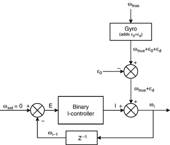
In order to explain the basic HDR algorithm, we make the simplifying assumption that when people walk, they move along straight lines – at least some of the time. In a later section we will introduce enhancements to the basic HDR method that allow us to drop the simplifying assumption of this section and deal effectively with more realistic conditions. The basic HDR algorithm functions essentially like a closed-loop control system. This is different from most other measuring systems, where signals pass from the sensor to the instrument's output in open-loop fashion. Figure 1 shows a block diagram of the closed-loop control system for the HDR method.
The HDR algorithm viewed as a closed loop control system. The binary I-controller is explained in the text.

Our above-stated simplifying assumption means that ωtrue=0 is correct at least some of the time. When ωtrue=0, then the only output from the gyro (after subtracting the static bias drift ε0) is εd. For our closed-loop control system, εd is a disturbance. It is well known from control theory that the error E in a closed-loop control system with a proportional-integral controller (PI-controller) or with just an I-controller converges to zero in steady state, if the control parameters are properly chosen and if the plant is of second or lower order. In the system of Figure 1, there is only a first order delay (in the feedback loop) and no plant. Thus, in steady state and because of the I-controller, E will be zero, which implies that the control signal I will track (but with an opposite sign) slow changes of εd with no offset. That is, I≅−εd under ideal conditions.
The ideal condition ωtrue=0 is, of course, rarely met. Indeed, ωtrue can briefly be orders of magnitude larger that εd, for example, when the subject walks around a corner. In that case a conventional I-controller does not work well, since it would respond strongly to large values of |ωtrue|, thereby overwhelming the integrator in the I-controller. To avoid this pitfall, the I-controller should be insensitive to the magnitude of the error signal E. This can be done by treating the error signal E as a binary signal that can have only one of two values: positive or negative. This way, the integrator I reflects the difference between the numbers of perceived left and right turns, as explained in the proceeding section.
For the implementation of the algorithm we should note that since the setpoint ωset is permanently set to zero, the following is true:
when ωi−1>0 (a perceived left turn), E is negative;
when ωi−1<0 (a perceived right turn), E is positive.
We can now formulate the binary I-controller:

where, i cFixed increment (°/sec)
An alternative way of writing Equation 4a is:

where, SIGN() is a programming function that determines the sign of a number. SIGN(x) returns 1 if x is positive, 0 if x=0, and −1 if x is negative.
The next element in the control loop adds the controller output to the raw measurement

where, ωiCorrected rate of rotation (°/sec).
If I≅−εd, as we assume for now to be the case under ideal conditions, in steady state, and because of the closed loop control system, then by substituting I≅−εd in Equation (5)

This result is desirable, since the unknown near-DC drift component is removed.
2.2. Practical Example
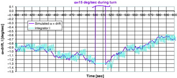
Figure 2 shows an example for the function of the closed-loop HDR control system. In this simulation a subject walked straight forward from t=400 to t=500 sec. From t=501 to t=512 the subject turned 180 degrees and then walked straight again. The purple (dark) curve shows the simulated ωtrue+εd. The cyan (light) curve shows −I tracking drift and oscillating around it with an amplitude of i c, just as we expected it to do under ideal straight line walking conditions. At t=501 the algorithm detects (in a way that will be explained later) that the subject is turning and freezes I, thereby effectively disabling itself. Once the turn condition ends at t=512, the binary I-controller increments − I repeatedly until −I is caught up with drift. Thereafter, −I continues to track drift again.
Example of −I tracking simulated ωtrue+εd. Most motion in this example is straight, except for a sharp 180-degree turn from T=500 to T=512 sec.

3. REALISTIC CONDITIONS
In order to explain the basic HDR algorithm we assumed that much of the walking was along perfectly straight lines. During ideal straight-line motion, any perceived right or left turn is indeed the result of drift. In reality, however, persons don't walk exactly straight. In the following section we discuss typical detractions from ideal straight line walking. Then, in Section 3.2, we present enhancements to the basic HDR algorithm, aimed at counteracting these detractions.
3.1. Detractions from Ideal Straight-line Motion
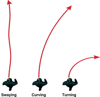
We distinguish between three types of motion that interfere with the ideal of perfect straight-line travel: Swaying, Curving, and Turning.
3.1.1. Swaying
We call motion that is intended to be straight but is not entirely straight due to the nature of walking swaying. An example for swaying is shown in Figure 3. Swaying produces very minor perceived left and right turns predominantly at the same frequency at which footfalls occur (about 1 Hz). There is also a lower-frequency sway, due to the difficulty of walking along a perfectly straight line. The walk of an intoxicated person is an extreme example of such low-frequency swaying. Errors due to swaying can be reduced significantly by low-pass filtering, as will be explained in Section 3.2.1.
Three types of non-straight motion: Swaying, Curving, and Turning.

3.1.2. Curving
Curving is the motion along an extended arc. This motion is potentially the least favourable one for the HDR method. That is because extended walking along an arc with a very large radius will be perceived continuously as a turn in the same direction and counteracted just like drift. In the worst case, if the arc curves, say, to the left, while the actual drift is to the right, then the HDR algorithm will try to counteract the perceived left turns and increase I, thereby actually increasing the error caused by drift alone.
Luckily, most walking inside man-made structures, especially along corridors, happens along straight lines. Also, when the path is unconstrained, people tend to walk straight toward a target, since that is the shortest and fastest way of reaching it. Outdoors, on trails or other paths that follow natural terrain, it is possible that the user has to walk along curving paths. In those cases, the basic HDR algorithm will not work well. Being aware of this limitation, we developed a method for detecting curving motion. This method, described in detail in Section 3.2.2, reduces the effect of HDR as long as the curving motion persists, so as to avoid the possibility of introducing greater errors.
3.1.3. Turning
Turning is a sharp but short change of direction. Examples are street corners or connections between corridors in a building. Turns are easily identified because the gyro measures much larger rates of rotation during turning than what can be expected as a result from drift. Thus, a simple test can be performed in software: if |ω| is larger than some threshold, then Equation 4 can be skipped altogether. However, because of the substantial low-pass filtering of the signal, we are using a more refined approach for diminishing the effect of turning, as will be explained in Section 3.2.
3.2. Refinements to the Basic HDR Algorithm
In this section we discuss two enhancements to the basic HDR algorithm: the double low-pass filter and the attenuator. Together, these enhancements overcome the two main challenges for the HDR method under real conditions: swaying and curving.
3.2.1. Double Low-pass Filter
In order to cope with the noisy measurements of rate of rotation, ωraw′, during walking, it is essential to apply a strong low-pass filter to ωraw′. A low-pass filter also helps reduce the effect of swaying, which in the PDR system has a dominant frequency of about 1 Hz. That is roughly the frequency at which footfalls occur in normal walking. Indeed, we found that a double low-pass filter with a time constant of τ=8 sec (i.e., a cut-off frequency of f c=1/τ=0·125 Hz) is quite effective at smoothing out much of the noise that is specific to walking. The two stages of the filter are implemented as
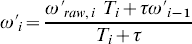
and
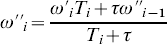
where:
T iTime interval, here the time since the previous footfall.
ω′, ω″Rate of turn after the first and second stage of the double low-pass filter, respectively.
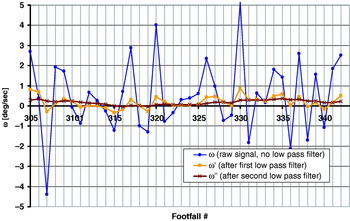
Figure 4 shows the effect of the double low-pass filter on a sequence of 35 footfalls during straight-line walking.
Measured ωraw′ during a sequence of 35 footfalls while walking along a nominally straight path, before and after applying one or both low-pass filters.

3.2.2. Attenuator and Threshold
The purpose of the attenuator and threshold is to reduce the impact of curving. Without the strong double low-pass filtering of Section 3.2.1, a simple threshold would be sufficient to distinguish between the large absolute values of ω due to turning and the much smaller values of ω due to drift. However, the low-pass filtering reduces the absolute values of ω, which makes them harder to distinguish from drift.
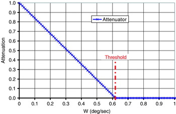
In order to reduce or eliminate the effect of large |ω| due to curving or turning, the HDR controller changes the I-controller's fixed increment i c adaptively, in inverse proportion to the magnitude of |ω|. For small |ω|, we want to increment the integrator I with the nominal increment i c, However, for larger |ω| we want to diminish the fixed increment i c, because larger |ω| suggests actual curving. To achieve this effect, i c is multiplied with an attenuation factor A:
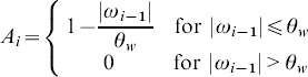
where, θw is threshold.
Figure 5 shows the attenuation function of Equation 7 graphically. The closed-loop control system of Figure 1, and thus the entire basic HDR algorithm, can now be implemented by:

and

Attenuation function with threshold.

3.2.3. De-lagging
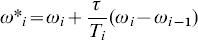
The HDR-corrected rate of turn, ωi, as computed by Equation (9), still has one problem: The double low-pass filter of Section 3.2.1, which was needed to remove swaying and walk-related oscillations prior to applying the HDR control loop, leaves ωi with a significant lag behind the raw ωi. If left this way, the subject's trajectory based on ωi would be a rather inaccurate representation of the true trajectory, as sharp turns become prolonged curves. However, this problem can be easily solved by reversing the effect of the double low-pass filter. To this end, we invert Equations (6a) and (6b):
and

where, ωd, i is the final, HDR-corrected and de-lagged rate of turn.
We can now compute the corrected heading by rewriting Equation (3):

where, ψ0 is the initial heading at the beginning of the walk.
The trajectory can be computed as:


where:
x 0, y 0initial position of the subject
D i distance travelled in interval i, as estimated by the PDR system described in Section 4.
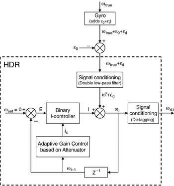
A block diagram of the entire HDR system is shown in Figure 6.
Final block diagram of the HDR system.

4. THE PERSONAL DEAD-RECKONING SYSTEM
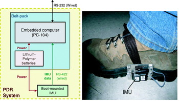
We tested the HDR algorithm under real-world conditions with our Personal Dead Reckoning (PDR) system. Before we present the experimental results in Section 5, we offer a brief description of the PDR system. Figure 7(Left) shows a block diagram of the PDR system, which we developed in earlier work at the University of Michigan (Ojeda and Borenstein, Reference Ojeda and Borenstein2007b). The system comprises of an IMU and a belt-pack that holds the system's computer, Lithium-Polymer battery pack, and custom electronics. The IMU is attached to the medial side of the user's right shoe, as shown in Figure 7(Right).
(Left) Block diagram of the PDR system. (Right) The Memsense nIMU unit is attached rigidly and permanently to the medial side of the user's right shoe.

On first glance it appears that this approach is destined to fail, since measuring linear displacement using the IMU's accelerometers is not very feasible. That is because data sampled from accelerometers must be integrated twice to yield linear displacement and this process tends to amplify even the smallest amount of bias drift.
However, we use a practical method that almost completely eliminates this problem – under certain operational conditions. We found that such operational conditions exist in legged motion; such as when people walk, run, or even climb. The method employed in the PDR system is called Zero Velocity Update (ZUPT). In the PDR system ZUPTing works because during every footfall, when the ball of the foot is firmly on the ground, the velocity of the sole at that point is zero. If velocity computed from the accelerometers is not equal to zero, then the accelerometers must be wrong and we can compute by how much the accelerometers are erring. A more detailed explanation of the PDR system is beyond the scope of this paper but can be found in Ojeda and Borenstein, (Reference Ojeda and Borenstein2007b). We should note, however, that with our implementation of ZUPT and some additional data manipulation we consistently achieve errors of 1–2% of distance travelled. A system similar to ours but apparently developed independently is described in Yun et al., (Reference Yun, Bachmann, Moore and Calusdian2007).
One problem with the PDR system, however, is that we can apply ZUPTing only to the accelerometers, but not to the gyros in the foot-mounted IMU. This is because even at footfall, the gyro data is too noisy to get a single, representative reading of rates of rotation. Therefore, drift in the gyros cannot be eliminated through ZUPTing. For the roll and pitch axes gyros, this is not a problem, because we can bound their errors by tilt data provided by the accelerometers during footfall. However, for the Z-axis gyro, which is the dominant source of data for computing the heading of the walking user, there is no good method for estimating or otherwise reducing drift. This is especially the case indoors, where GPS and magnetometers are not viable alternative sources for heading information. It is this limitation of the IMU's Z-axis gyro that motivated the present work.
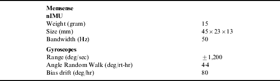
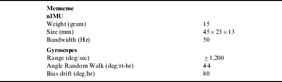
The IMU used in our PDR system is the nano-IMU (nIMU in short), a MEMS-based unit made by Memsense (MemSense, Reference MemSense2008). Some key specifications for that IMU are listed in Table 1. The nIMU's gyros work on the basis of the Coriolis Effect. A potentially severe limitation of Coriolis-based gyros is that they are sensitive to linear accelerations normal to the measurement axis of the gyro (Ojeda and Borenstein, Reference Ojeda and Borenstein2007a). Due to the relatively high accelerations on the foot during walking, errors induced by this effect can be many times larger than errors due to drift alone. This must be kept in mind when examining the experimental results in Section 5, where uncorrected errors (i.e., result from the standard PDR system without HDR corrections) are notably larger than what can be explained by the nIMU's bias drift of 80 deg/hr alone (see Table 1). Moreover, due to manufacturing variations, there are large variations in the degree to which different units of the exact same nIMU model are affected by linear accelerations. Another problem with the nIMU is its sensitivity to temperature variations, which are especially noticeable when mounted on the outside of the user's boot, where the unit is exposed to ambient air.
Key specifications of the Memsense nIMU.
Correcting for sensitivity to linear accelerations is particularly difficult because of the complex spatial motion performed by the foot during walking. However, it is reasonable to assume that the acceleration sensitivity, which follows similar patterns during each step, can be averaged over several steps and considered as a near-constant – but unknown – disturbance, as long as the user's gait stays the same. When the user changes gait, then the value of that near-constant disturbance changes. For this reason, the acceleration sensitivity acts much like gyro drift. As will be shown in the next section, the HDR method successfully reduces these large errors regardless of whether they were caused by drift alone or by the combined ill-effects of drift and acceleration sensitivity. Similarly, since temperature changes are gradual, their effect on the gyros can also be treated as drift and compensated for with the HDR method.
5. EXPERIMENTAL RESULTS WITH THE REAL PDR SYSTEM
This section presents real experimental results obtained with the PDR system described in the foregoing section, with and without the application of the HDR system. These results focus on two types of experiments: (1) A set of straight-line walks aimed at demonstrating the basic functioning of the proposed HDR method, and (2) a set of long, complex closed-loop walks on partially curving and partially sloped sidewalks.
5.1. 1000-metre Straight-line Walk
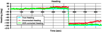
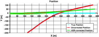
In this experiment the subject walked along a reasonably straight line along a sidewalk of a city street. He started at coordinates (0, 0) and walked 500 m in X-direction. Then, the subject turned around on the same sidewalk and walked back to the starting point (0, 0). We performed this experiment three times. Figure 8 plots the heading errors with and without HDR correction for Walk 2. Figure 9 shows the trajectory with and without HDR correction for Walk 2.
Heading as computed with and without HDR. After turning for 180° midway through the experiment, the final heading of the subject should be 180°. The plot corresponds to Walk #2.

Trajectory of a walking person with and without HDR. Note that the X and Y-axis have different scales. The plot corresponds to Walk #2.

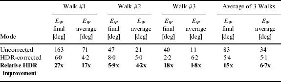
Table 2 tabulates the relevant quantitative results for all three walks. The average heading error for each walk was computed by comparing the estimated heading with the ground truth heading at each step, and then averaging the individual heading errors for the entire walk. Ground truth heading was implied by the simple conditions of this experiment: a constant 0° for the first 500 metres and a constant 180° after the 180-degree turn.
Final and average heading errors for three 1000-metre straight line walks.
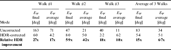
We regard the average heading error, E Ψ, as the most useful quantitative measure of performance for a particular walk. Another useful measure of performance is the final heading error, at the end of each walk. This final heading error suggests how heading errors and position errors would develop if the walk was continued.
5.2. Closed-loop Walk
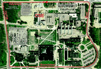
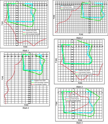
A more complex experiment comprised five closed-loop walks along the path shown in Figure 10. The total walking distance of the closed-loop path is about 1,800 m (1·12 miles) and the duration of these walks was on average 20 minutes. A particular challenge is the continuously curved street (Beal Avenue) on the east side. As discussed earlier in this paper, continuous curving is a challenge for the HDR algorithm because a continuous curve is difficult to distinguish from the perceived curving caused by drift.
Nominal trajectory for the large round walk.

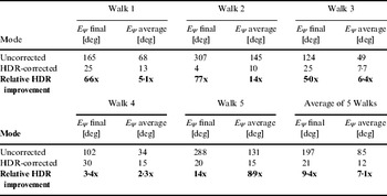
We used a consumer-grade hand-held GPS unit to measure ground truth. Since position data from GPS is quite noisy we manually smoothed the GPS data and also filled in missing data points resulting from occasional GPS outages. The smoothed ground truth data was used to compute the momentary heading error at each footfall, as well as the average heading error for each complete walk. Figure 11 shows the result of the five walks. For each walk we plotted the smoothed ground truth, as well as the trajectory estimated by the PDR system with and without HDR correction. Table 3 summarizes the results in terms of average and final heading errors.
Results of five closed-loop walks of 1,800 m length and 20 minutes duration. Each walk was done with a different nIMU and under different temperature conditions.

Final and average heading errors for the five closed-loop walks of Figure 11.

In this set of five walks we used five different units of the exact same model of the Memsense nIMU. The model number is NA10-1200F050R. As is evident in Figure 11 the uncorrected results differed dramatically among the five walks. We believe the main reasons to be:
• There are dramatic variations in the sensitivity to acceleration among different units of the same model of the nIMU. These variations are consistent, demonstrable, and have been confirmed in conversation with a Memsense representative.
• The five walks were conducted on different days under cold winter weather conditions. For all walks we performed the initial warm-up indoors, while we measured the static bias drift e 0 outdoors, immediately prior to walking. As a result of the transition from warm indoor temperatures to cold outdoor temperatures, the IMUs underwent substantial changes in temperature in the course of the 20-minute walks.
• The streets on the west and east sides have noticeable inclines. When the subject walks up or down those inclines, the average direction of the gravity vector relative to the shoe-mounted IMU differs from that direction during walking on level ground. Since the gyros of the MEMS-based nIMUs are sensitive to accelerations, this change causes drift-like errors.
• The five walks were performed by two different subjects.
5.3. Discussion
The results of Table 3 show a seven-fold improvement in the average heading error and an almost 10-fold improvement in the final heading error. We should also note that in all experiments of Section 5 (as well as in other experiments, not covered here), we used identical values for the tunable parameters.
Given the heuristic nature of the algorithm and the trial-and-error approach to tuning the parameters, it would be desirable to include more test sets and to tune the HDR parameters so as to provide good results for a large number of test sets. It is clear that if a set of parameters is near-optimally tuned for a set of n test sets and produces an overall score of X n, then adding the n+1th test set will require re-tuning the parameters, which will produce a lesser score, X n+1<X n. On the other hand, once a large number of test sets are reflected in the parameters, adding more test sets will result in only small reductions in score.
6. CONCLUSIONS
In this paper we proposed the HDR method for reducing errors due to gyro drift in a personnel tracking system. The basic heuristic assumption is that much walking happens along reasonably straight lines. Whenever that is the case, the closed-loop control approach in our system leads the controller output, −I, to track the near-DC component of the drift. Subtracting I from the gyro-measured rate of turn data then effectively eliminates drift.
The HDR system introduces errors of its own, in two ways:
• The basic HDR algorithm cannot distinguish well between drift and actual curving motion. To reduce this undesirable behaviour, we introduced the attenuator enhancement. With this enhancement the HDR algorithm effectively suspends its operation for as long as the actual curving motion continues. Then, when straight line motion resumes, HDR corrections resume and −I resumes its tracking of drift. Heading errors due to drift while HDR was suspended cannot be recovered.
• Even during straight-line motion, there is always a residual offset between −I and drift because the near-DC component of drift never reaches steady state. This residual offset incurs heading errors that cannot be recovered.
Despite the errors that HDR introduces, its corrective effect when used with high-drift gyros outweighs its errors by a wide margin, as is apparent from the experimental results. For the nIMU used in our PDR system (which incurs errors not just because of drift but also because of the gyros' sensitivity to linear accelerations and temperatures), HDR reduces heading errors by close to one order of magnitude.
The HDR method is less effective in typical indoor environments, where turns around corners are sharper and distances between sharp turns are shorter than outdoors. Under these conditions the strong low-pass filtering causes unacceptable distortions of ω. Working with a less strong low-pass filter solves that problem, but reduces the effectiveness of HDR to a mere two-fold improvement. For that reason, we are currently developing a special indoors-only version of HDR that will be published in a forthcoming paper.
ACKNOWLEDGEMENTS
This material is based upon work supported by Mercury under Contract No. UM-PDR-001 as well as by the U.S. Dept. of Energy under Award No. DE FG52 2004NA25587.