Introduction
The natural surface plasmon polariton (SPP) is a surface wave transmitting along the dielectric/metal interface at the infrared and optical band [Reference Maier1]. Owing to its ability to bind the electromagnetic field within the sub-wavelength range to the interface, it is quickly applied to the optical band and the plasmonics has been accordingly developed [Reference Ozbay2,Reference Barnes, Dereux and Ebbesen3]. The spoof SSP (SSPP) is a kind of manmade periodical structure to simulate the sub-wavelength binding ability of the SPP in the low-frequency band. Owing to the constraint ability, diverse microwave devices based on SSPP are achieved, such as filters [Reference Chen, Li, Yang and Chen4], power dividers [Reference Shen, Cui, Martin-Cano and Garcia-Vidal5], couplers [Reference Zhao, Feng, Zhu, Chen, Liu and Jiang6], and frequency dividers [Reference Gao, Hui Shi, Shen, Feng Ma, Xi'Ang Jiang, Li and Cui7], etc. Because the SSPP also has the wide low-pass frequency characteristics and the different design approach from conventional microwave filters, it is more applied in microwave filters.
The dispersions of SSPP units usually behave the low-pass frequency characteristics. However, when they are applied into filters, the filters generally behave larger return loss and insertion loss at the near-zero-hertz bands [Reference Liu, Li, Ning and Xu8]. This defect forces the SSPP units with low-pass dispersions to be applied into band-pass SSPP filters [Reference Liu, Li, Ning and Xu8–Reference Zhao, Zhang, Wang, Yu, Li, Su and Shen10]. Researchers tried much work to solve this problem. Ref. [Reference Xu, Li, Liu, Chen, Xu, Ning and Gu11,Reference Liu, Li, Xu, Ning, Chen and Gu12] attempted to change the structures of SSPP units or the approaches of signal feeding, where the periodicities of the SSPP and mode conversion parts were strictly maintained. Both of which improved the return losses of the near-zero-hertz bands, but their insertion losses and return losses of the near-zero-hertz bands are still greater than those of the higher frequency passbands. Ref. [Reference Zhang, Wu, Zhang, Ding and Sha13] optimized the structural parameters of the mode conversion parts, thus the regularity of which is broken. Consequently the return losses and insertion losses of the near-zero-hertz bands are much reduced and which are lower than those of the higher frequency bands. However, the SSPP part was not taken into optimization and the dispersion variations in the optimization processing are not considered. In addition, the SSPP units of Ref. [Reference Xu, Li, Liu, Chen, Xu, Ning and Gu11–Reference Zhang, Wu, Zhang, Ding and Sha13] all are double comb-shaped ones. The single comb-shaped SSPPs, which have simpler structures, are less attempted to implement a low-pass filter (LPF) with nice performances.
Owing to the too large return loss and insertion loss at the near-zero-hertz band, the single comb-shaped SSPP filter in Ref. [Reference Zhao, Zhang, Wang, Yu, Li, Su and Shen10] only can be a band-pass one. Ref. [Reference Zhao, Zhang, Zhao and Tang14] simplified the filter's structure from Ref. [Reference Zhao, Zhang, Wang, Yu, Li, Su and Shen10], but the new filter's performance at the low-frequency band was not presented. This paper reduces the cutoff frequency of the filter from Ref. [Reference Zhao, Zhang, Zhao and Tang14], where lengths of the SSPP units in the mode conversion parts are changed from fixed values into progressive ones. The filter's structural parameters of mode conversion and SSPP parts are also taken into optimization. Both optimized and unoptimized filters are simulated and fabricated to make the performance comparison. The measurement result demonstrates that the optimized filter provides lower insertion loss and return loss, smaller filter size, and better out-of-band rejection than the unoptimized one. The dispersion curves of two filters are also compared to study the dispersion variations in the optimization processing, which interprets the reason of the improved filter performances.
Filters simulation
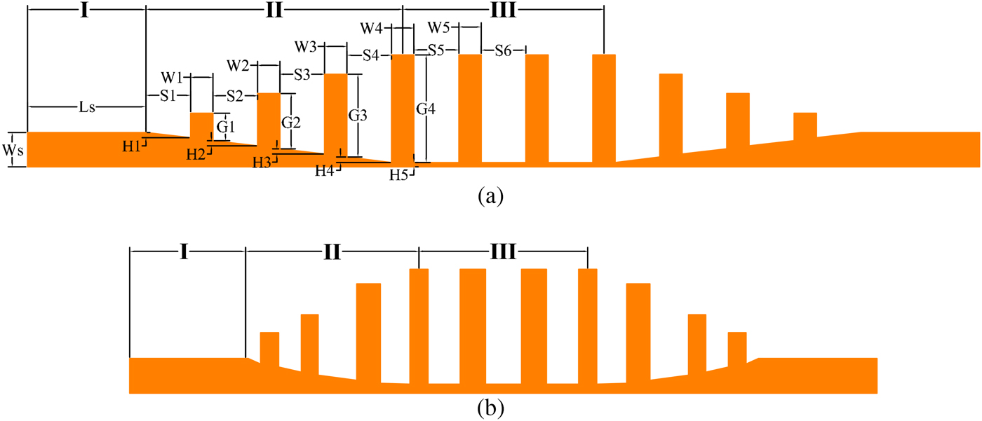
The designed filters are illustrated in Fig. 1. The unoptimized filter in Fig. 1(a) is a representative periodical SSPP filter [Reference Liu, Li, Ning and Xu8,Reference Zhao, Zhang, Wang, Yu, Li, Su and Shen10,Reference Liu, Li, Xu, Ning, Chen and Gu12,Reference Zhao, Zhang, Zhao and Tang14] and the second is a novel optimized one. Both the two filters can be divided into three parts: Part I, II, and III. Part I is the micro-strip which connects with SMA connectors and transmits quasi-TEM wave. Width of the micro-strip is W s = 1.54 mm and the corresponding characteristic impedance is 50 Ω. Part III is a SSPP waveguide composed of three SSPP units and only TM wave can be transmitted in. Part II is a momentum matching and mode conversion part, which transforms quasi-TEM and TM waves bidirectionally and the final performances of the filters are sensitive to the structural parameters. Substrates of the both filters are RT/duroid 5880, whose permitivity is 2.2 and the substrate thickness is 0.508 mm.
In the SSPP part of Fig. 1(a), the SSPP units are periodically arrayed, whose groove depths all are G 4 = 4.82 mm and the groove widths are S 4 = 2.0 mm. The transformation units of Part II have the similar structure and the same horizontal arrangement spacings with the SSPP units in Part II. But their vertical lengths of the bars change sequentially in the step of 0.87 mm. The gradient fixed slope strings the units together at the bottom of the mode conversion part. The simulation model of Fig. 1(a) is built in the commercial full-wave simulation software Hyperlynx, which is optimized with a goal of the smaller S 11, then the optimized filter in Fig. 1(b) is presented. Simulated S parameters of the two filters are displayed in Fig. 2 and the structural parameters comparison is listed in Table 1.
Schematics of the designed filters: (a) the unoptimized filter; (b) the optimized filter.

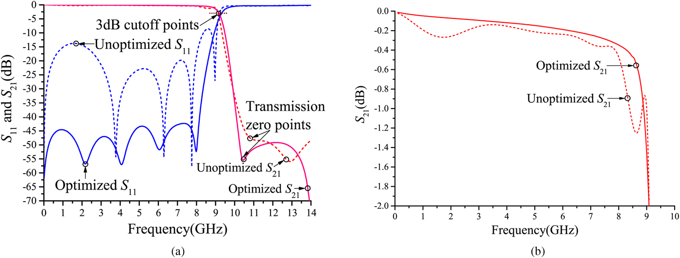
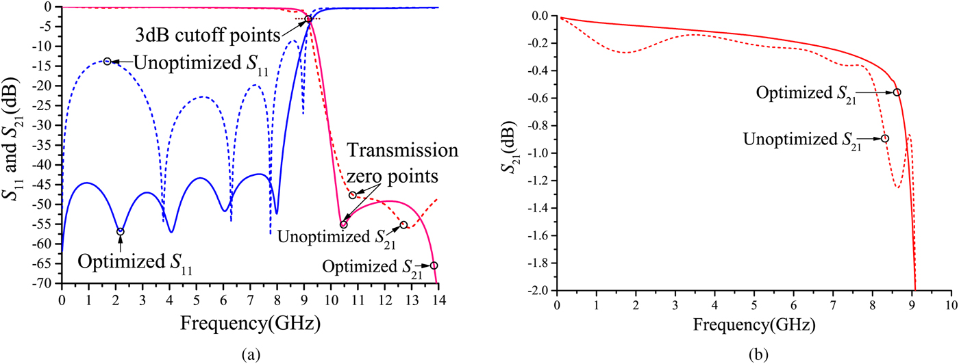
Simulation S parameters of the designed filters.
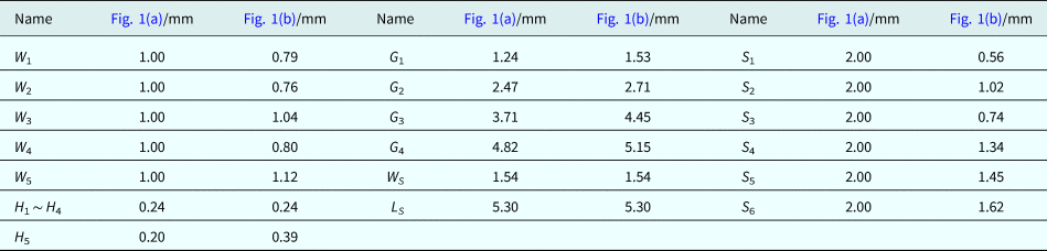
Structural parameters of Fig. 1

As Fig. 2(a) shows, in the unoptimized filter, the return loss of the lower passband is larger than that of the higher band, but which is much reduced in the optimized one. The maximal return losses of the optimized and unoptimized filters in the whole pass-band are −42.3 and −8.3 dB, respectively. Hence the optimization process reduces the return loss by 34 dB. Cutoff frequencies of the optimized and unoptimized filters are 9.21 and 9.17 GHz, respectively. The transmission zeros of which are 10.45 and 10.80 GHz, respectively, and their corresponding rejection depths are −55.5 and −47.6 dB. Hence the optimized filter has deeper rejection depth at the transmission zero point and narrower transition bandwidth.
In Fig. 2(b), the optimized S 21 approximates to a straight line, but the unoptimized one has more fluctuations. In the band of 0.1–8.7 GHz, S 21 of the optimized filter varies slowly from −0.01 to −0.61 dB and that of the unoptimized one varies from −0.02 to −1.23 dB. The average in-band insertion losses of the optimized and unoptimized filters are 0.16 and 0.27 dB, respectively. The comparison of simulation S parameters proves the optimized filter has lower insertion loss and return loss, and steeper and deeper out-of-band rejection.
As Table 1 demonstrates, structural parameters of Fig. 1(a) are regular, which is a representation of the present SSPP filter design approach whose parameter variation tendencies are fixed. In that way, the SSPP parts are periodical and the variation steps of mode conversion units are fixed [Reference Liu, Li, Ning and Xu8,Reference Zhou and Yang15–Reference Li, Sun, Sun, Wang, Song, Liu, Chen and Gu17]. Specifically, in the mode conversion parts, the steps between the vertical bars' lengths, the spacings between the vertical bars and the gradient of the entire slope, all remain unchanged [Reference Xu, Li, Liu, Chen, Xu, Ning and Gu11,Reference Zhang, Wu, Zhang, Ding and Sha13,Reference Xiao, Chen and Kong18–Reference Zhang, Zhang, Yin, Pan and Cui20]. Overall, the whole unoptimized filter exhibits strong regularity.
However, as the table illustrates, the regularity is broken in Fig. 1(b), where the structural parameters of the SSPP units no more are the same. In the mode conversion parts, lengths of the vertical bars do not increase in a constant step and the bars also no more array in a equal space. Gradients of the slopes in mode conversion parts are constant in each unit but diverse in different units. It is these irregular structural parameters that improve the filter's performances.
Dispersion analysis
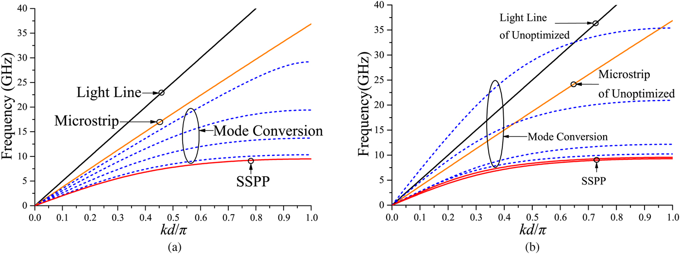
The designed filters are divided into individual SSPP units to simulate their dispersions. The simulation is finished in CST Microwave Studio, corresponding results are illustrated in Fig. 3, where d is the width of the simulated units, Light Line is the dispersion of the electromagnetic wave transmitting in the vacuum, and Microstrip is the dispersion of the microstrip in the filters. The Light Line is directly bound up with the phase velocity of vacuum and it is calculated by ω = ck, where ω is the angular frequency, c is the light velocity in the vacuum, and k is the wave number. The red curves are dispersions of the SSPP units, which decide the cutoff frequency of the filter. The blue dash curves are dispersions of the mode conversion units, which indicate the mode conversion process from the microstrip to the SSPP parts.
Dispersion simulation results of SSPP units and mode conversion units in the designed filters.

According to the mechanism of SSPP, the unit whose dispersion curve is below that of the microstrip has greater insertion loss than the microstrip. Conversely, the unit whose dispersion curve is above that of the microstrip has smaller insertion loss than the microstrip [Reference Maier1]. In Fig. 3, all the blue and red curves of Fig. 3(a) are below the solid orange line, but part of the blue curves of Fig. 3(b) are above the solid orange line, hence the overall insertion loss of the optimized mode conversion part is smaller than that of the unoptimized one. Since the lengths of the microstrips (L s) in the two filters are the same and the dispersion curves of the SSPP units (red curves) in the two filters are approximate, the reduced insertion loss in the mode conversion part is the main reason of the reduced insertion loss in the optimized filter.
In Fig. 3(b), the second blue curve above the red curve is closer to the red curves than that of Fig. 3(a), whose physical properties are more closer to those of the SSPP. Thus the corresponding mode conversion unit has a stronger electromagnetic binding capability, which enhances the binding ability of the whole filter and further increases the out-of-band rejection level of the filter.
According to the equation ω = ck and the coordinate in Fig. 3, it can be derived that the gradient of the dispersion figure is
 $${\,f \over kd/\pi}={c \over 2d}.$$
Therefore, the smaller d (narrower unit width) corresponds to the greater gradient. The gradients of the blue curves on the upper side of Fig. 3(b) are greater than those of Fig. 3(a), thus the widths of the corresponding mode conversion units in the optimized filter are narrower than those of the unoptimized ones. Similarly, considering that the lengths of the microstrips are not reduced, it can be the main reason why the filter's length is reduced.
Fabrication and measurement
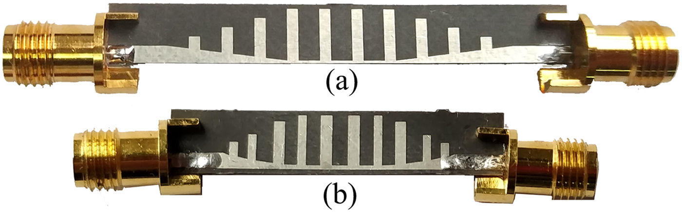
In order to prove the performance improvement of the optimized filter, both the two filters are fabricated, photographs of which are displayed in Fig. 4. Sizes of the unoptimized and optimized filters are 42.60 mm × 16.30 mm (1.69λg × 0.66λg) and 33.43 mm × 12.54 mm (1.3λg × 0.5λg), respectively, where λg is the guided wavelength of the cutoff frequency. Therefore, size of the optimized filter is 9.17 mm × 3.76 mm (0.39λg × 0.16λg) smaller than the unoptimized filter. In the measurement, the filters connect with SMA connectors as Fig. 4. And they are put in the air and directly connected with the vector network analyzer. Hence the measured insertion loss includes radiation losses, dielectric losses, and conductor losses. The measurement results are illustrated in Fig. 5.
Photographs of the fabricated filters. (a) The unoptimized filter; (b) the optimized filter.

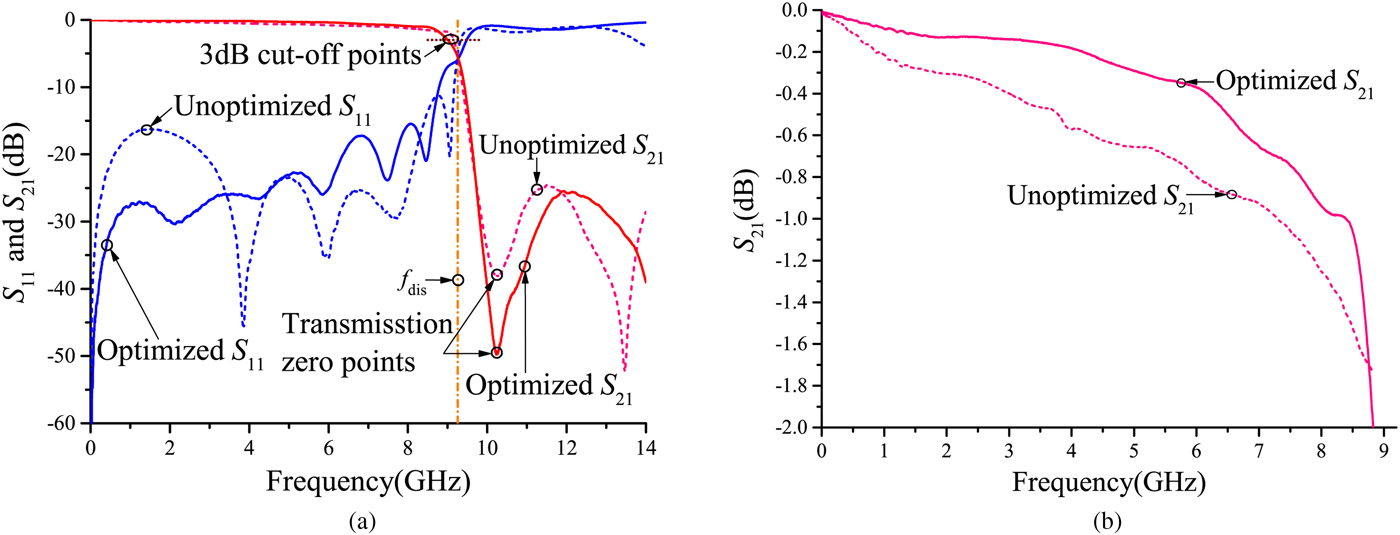
Measurement S parameters of the designed filters.

As Fig. 5(a) illustrates, S 11 of the optimized filter increases as the frequency grows, which is caused by the insufficient fabrication precision. Nonetheless, in the band of 0–4 GHz, maximal S 11 of the optimized and unoptimized filters are −25.9 and −16.2 dB, respectively. Hence the return loss of the low-frequency band reduced 9.7 dB after the optimization. Cutoff frequencies of the unoptimized and optimized filters are 9.24 and 9.15 GHz, respectively. Frequencies of the transmission zeros of them are 10.25 and 10.26 GHz, respectively. And the corresponding rejection depths are at −49.9 and −38.0 dB, respectively. Accordingly the optimized filter provides deeper rejection at the transmission zero point. In Fig. 5(a), f dis is the dispersion's cutoff frequency of the SSPP unit in the optimized filter, which is 9.25 GHz. Thus f dis approximates to the filter's cutoff frequency and the transmission zero point, which is the reason why the transmission zero point locates in that frequency point.
In Fig. 5(b), in the passband of 0.1–8.4 GHz, S 21 of the optimized and unoptimized filters decrease from −0.02 to −1.01 dB and from −0.03 to −1.48 dB, respectively. And the average passband insertion losses are 0.41 and 0.67 dB, respectively. Thus the insertion loss decreases by 0.26 dB in the optimization. Consequently, according to Figs 4 and 5, the optimized filter provides smaller insertion loss and return loss , more compact filter size, and deeper out-of-band rejection.
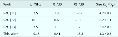
The comparison between the SSPP LPFs and our optimized LPF is listed in Table 2, where f c is the filter's cutoff frequency, λg is the guided wavelength of f c, IL is the insertion loss of the passband, RL is the return loss of the passband. According to the table, the optimized filter provides smaller insertion loss and smaller filter size. And its return loss also keeps at a small value.
Performances comparison with SSPP LPFs

Conclusion
By changing lengths of the SSPP units in the mode conversion parts into progressive from fixed, the high-frequency single comb-shaped SSPP LPF is introduced into the lower frequency band with fine performances. The optimization on the structural parameters further promotes the filter's performances and makes it more suitable for engineering. In addition, the comparison with similar filters proves the improved performance of the proposed filter. The dispersion analysis on the unoptimized and optimized filters interprets the reason why the optimized filter provides such a performance. The results indicate that breaking the regularity of traditional SSPP filters promotes the filter's performances.
Author ORCIDs
Luping Li, 0000-0001-9294-6730; Lijuan Dong, 0000-0002-1773-0777; Peng Chen, 0000-0003-1444-5097
Acknowledgment
This work was supported by the National Natural Science Foundation of China 61601088 and 61571093.
 Luping Li received his Bachelor degree in electronic information engineering from Chengdu University of Information Technology, Chengdu, China in 2016. Now he is studying his Master degree in the University of Electronic Science and Technology of China, Chengdu, China since September 2016. His research interests are RF/microwave filters.
 Lijuan Dong received her Bachelor degree in biomedical engineering from Chengdu University of Information Technology, Chengdu, China in 2017. She is studying her Master degree in the University of Electronic Science and Technology of China, Chengdu, China since September 2017. Her research interests are RF/microwave filters and electroencephalogram signal processing.
 Peng Chen received the Bachelor degree in electronic science and technology and the Ph.D. degree in circuits and systems from the University of Electronic Science and Technology of China, Chengdu, China in 2009 and 2015, respectively, where he became a lecturer in 2015. He was also a visiting scholar in Tohoku University, Sendai, Japan from November 2017 to November 2018. His main research interests are design and optimization of RF and microwave devices and systems.
 Kai Yang became an associate professor and a professor of University of Electronic Science and Technology of China, Chengdu, China in 2001 and 2007, respectively. He became a senior member of Chinese Institution of Electronics in 2006. His research interests are RF/microwave circuits and systems, superconducting microwave components, and circuit theory.