1. Introduction
The development of biologically inspired robotic systems has gained considerable attention for addressing engineering challenges through innovative designs [Reference Ma, Gong, Tian, Wu, Pan, Yin, Liu and Chen1–Reference Wu, Xiao, Zhao, Mou, Cui and Liu2]. Flapping-wing robots, inspired by natural fliers such as birds, insects, and bats, stand out for their efficiency, agility, and versatility, making them ideal for applications like search and rescue, environmental monitoring, and surveillance, especially in complex environments where conventional systems struggle [Reference Wang, Zhang, Zou, Meng, Zhao and Wei3–Reference Tsuchiya, Aono, Asai, Nonomura, Ozawa, Anyoji, Ando, Kang and Pohly7].
Bat-inspired robots offer unique advantages due to bats’ distinct flight characteristics and wing morphologies. Bats have highly articulated, foldable wings with a flexible membrane stretched over an elongated skeletal framework supported by finger-like bones [Reference Swartz and Konow8–Reference Hedenström and Johansson10]. This membrane allows dynamic adjustments to wing shape and surface area, enabling precise maneuvers and energy-efficient flight. During the upstroke, bats fold their wings to reduce drag, while during the downstroke, they expand them to maximize lift and thrust [Reference Frank, Frishkoff, Mendenhall, Daily and Hadly11–Reference Singh, Zhang and Zhao12]. These advanced flight dynamics make bats an ideal model for robotic design.
In bat-inspired robotic systems, morphing mechanisms are fundamental for replicating the dynamic wing movements of real bats. These mechanisms enable robots to alter their wing shape, folding and unfolding the wings to improve both maneuverability and energy efficiency during flight. Various approaches have been explored to replicate these morphing capabilities, including the use of compliant materials such as soft polymers [Reference Yin and Zhang13–Reference Ruiz, Acosta and Ollero14] or shape-memory alloys (SMAs) [Reference Shakiba, Ayati and Yousefi-Koma15–Reference Duan, Guo and Liu16], as well as articulated frameworks with multiple degrees of freedom (DOFs) [Reference Duan, Guo, Mao and Liu17–Reference Hoff, Ramezani, Chung and Hutchinson20]. For example, researchers at the University of Illinois have focused on material innovation, developing lightweight and elastic membranes that closely mimic the unique properties of bat wings [Reference Ramezani, Chung and Hutchinson21]. At Brown University, SMA-actuated structures have been designed to simulate the morphing muscles of bats, with SMAs functioning as artificial biceps and triceps to drive motion – providing one DOF at the elbow and three DOFs at the wrist [Reference Colorado, Barrientos, Rossi and Breuer22]. Similarly, Memorial University proposed an articulated bat-inspired morphing wing, leveraging the weighted sum method and principal component analysis (PCA) for wing shape adaptation [Reference Sui, Zou and Riskin23].
Despite significant advancements, substantial challenges persist in the development of effective bat-inspired robotic systems. One of the primary obstacles is accurately replicating the intricate wingbeat kinematics observed in real bats. Current designs often struggle to achieve the precise synchronization between flapping and folding motions, which is essential for efficient and agile flight [Reference Colorado, Rossi, Zhang and Barrientos24]. Additionally, materials used for soft-wing structures frequently fall short in terms of resilience and flexibility, failing to replicate the dynamic, real-time adjustments that bats perform during flight. Achieving an optimal balance between flexibility and structural integrity remains an ongoing obstacle. Moreover, actuation systems for wing deformation are often bulky or energy-intensive, which adversely affects the overall efficiency and flight endurance of bat-inspired robots [Reference Sui and Zou25]. Addressing these limitations is crucial for advancing the design and performance of next-generation flapping-wing robotic systems (Figure 1).
DoFs of a biological bat [Reference Riskin, Willis, Iriarte-Diaz, Hedrick, Kostandov, Chen, Laidlaw, Breuer and Swartz27].

In this paper, we present a bat-inspired flapping-wing robot equipped with foldable, silicone-based wings. The robot uses a one-degree-of-freedom (DOF) revolute-spherical-spherical-revolute (RSSR) mechanism to replicate the flapping motion, while a one-DOF Watt six-bar linkage is utilized to facilitate wing folding. To enable realistic movement, kinematic models for both flapping and folding mechanisms were developed. Simulation results demonstrate that the robot achieves a coupled flapping-folding motion, with wings extending during the downstroke and folding during the upstroke. Untethered outdoor flight tests further validate the robot’s advanced flight capabilities. The primary motivations for this research are twofold: first, to enhance understanding of flapping aerial robotics and explore the potential of soft-winged robots for applications in environments shared by humans and robots; second, to provide a robotic platform for advancing biological studies of bat flight.
This paper is organized as follows: Section 2 introduces a novel design for a bat-inspired robot, focusing on the forelimb wing structure and actuation strategies. In Section 3, the kinematic model for both the folding and flapping mechanisms of the robot is developed. Section 4 presents an evaluation of the robot’s flight performance, based on experimental tests conducted with a physical prototype. Finally, Section 5 summarizes the key conclusions and discusses potential directions for future work.
2. Model design
Given the stringent weight and power constraints associated with flapping flight, a synergistic design approach was employed to integrate multiple mechanical linkages into the flight mechanism of the bat-inspired robot. Figure 2 illustrates the structural layout of the robotic bat, which utilizes four actuators to enable biologically inspired movements. These movements include synchronized flapping and folding of the forelimbs, as well as independent dorsoventral motion of each hindlimb.
Design of the bat robot and wing frame configurations. The body frame (
 $\mathcal{F}_{b}$
) is positioned at the robot’s center of gravity, while the shoulder frame (
 $\mathcal{F}_{s}$
) originates at the shoulder joint. The humerus frame (
 $\mathcal{F}_{h}$
) aligns with the shoulder frame, sharing its origin and -axis. The radius frame (
 $\mathcal{F}_{r}$
) is defined at the elbow joint, and the wrist frame (
 $\mathcal{F}_{w}$
) is located at the wrist joint.

2.1. Actuation mechanism
-
• Forelimb Actuation: To achieve wing kinematics that enable the wings to fold during the upstroke and extend during the downstroke, two types of actuators are employed: a morphing actuator and a flapping actuator. The morphing actuator operates through a crank-slider mechanism, where the slider is constrained to linear motion along a guide rail. A connecting rod extends from both sides of the slider, linking it to the proximal ends of the humerus via a Hooke hinge (see Figure 3(d)). This configuration restricts the range of wing folding and allows precise control of wing morphing via a servo motor. In parallel, the flapping actuation system utilizes a spatial crank-rocker mechanism. Here, the distal end of the rocker is hinged to the proximal end of the humeral connecting rod, facilitating symmetrical up-and-down movements of the left and right wings.
-
• Hindlimb Actuation: From a kinematic perspective, bat ankles move ventrally during the downstroke and dorsally during the upstroke [Reference Cheney, Ton, Konow, Riskin, Breuer and Swartz26]. Inspired by this natural motion, two asynchronously active legs were designed to control the trailing edge of the membrane wing. As illustrated in Figure 3(d), each leg is connected to the body through an active revolute joint, enabling dorsoventral movements within a plane tilted relative to the parasagittal plane. Unlike biological bats, the robot’s legs do not perform mediolateral movements, as studies by Riskin et al. [Reference Riskin, Willis, Iriarte-Diaz, Hedrick, Kostandov, Chen, Laidlaw, Breuer and Swartz27] indicate that such movements are less significant in natural bat locomotion.
Structure of the morphing wings: (a) The left side illustrates the wings in their fully extended state, while the right side shows the skeletons in a fully folded configuration. (b) Close-up view of the wrist joint, emphasizing passive digit deformation. (c) Rear view of the fully stretched wing skeleton, highlighting the three curved digits. (d) Close-up view of the actuation mechanism responsible for forelimb and hindlimb movement.

2.2. Wing structure and components
The bat-inspired robotic wing is divided into two segments: an inner and an outer section. The inner segment, referred to as the “arm wing,” consists of two primary hinged components, representing the humerus and radius (see Figure 3(b)). These components are actuated through a series of linkages that control the arm’s extension and flexion. This motion is governed by the linear distance between the shoulder and the proximal end of lever 1, indicated by red double arrows in Figure 3(a).
The outer section, called the “hand wing,” is supported by three digits that span its surface. These digits are specifically designed to curve downward, creating a positive airfoil curvature that enhances lift efficiency (see Figure 3(d)). All three digits connect proximally to the distal carpus. Additionally, digits 1 and 3 are, respectively, hinged to the radius and radial support rod via auxiliary linkages, as shown in Figure 3(b). This setup allows passive adjustments of the angles between digits during wing deformation, enhancing the folding ratio. For details on movement, see Section 3.2.
3. Kinematic analysis
3.1. Kinematic analysis of the flapping mechanism
To ensure flight stability through symmetrical movement, a spatial crank-and-rocker mechanism is utilized to achieve the flapping motion of the wings. A schematic representation of the mechanism’s structure is shown in Figure 4. The parameters
 $a , b$
, and
 $c$
denote the lengths of the rocker, link, and crank, respectively. The two joints on the link are spherical joints. The initial structural parameters of the flapping mechanism are provided in Table I.
As a spatial four-bar mechanism, the movement planes of the crank and the rocker are orthogonal. Assuming that
 $\theta$
and
 $\varphi$
denote the angular positions of the crank and rocker, respectively. The position vector of point
 $B$
and
 $C$
can be expressed as:
 \begin{equation}{\boldsymbol{r}_{B}=\left[\begin{array}{l@{\quad}l@{\quad}l} -a\cos \theta & d & a\sin \theta \end{array}\right]^{T} } \end{equation}
 \begin{equation}{\boldsymbol{r}_{C}=\left[\begin{array}{l@{\quad}l@{\quad}l} -s & c\cos \varphi & c\sin \varphi +h \end{array}\right]^{T} } \end{equation}
Structure parameters and initial conditions of the flapping mechanism (mm).

Flapping mechanism: (a) Axonometric view, and (b) sketch of the RSSR space four-link mechanism.

To establish the relationship between the input angle
 $\theta$
and flapping angle
 $\varphi$
, the geometric constraint is given by:
 \begin{equation} \left\| \boldsymbol{r}_{C}-\boldsymbol{r}_{B}\right\| ^{2}=b^{2} \end{equation}
Here,
 $\| \cdot \|$
indicates the 2-norm or amplitude of the vector
 $\boldsymbol{r}_{C}-\boldsymbol{r}_{B}$
.
By substituting the vectors
 $\boldsymbol{r}_{B}$
and
 $\boldsymbol{r}_{C}$
into Eq. (3), we have:
 \begin{equation} \left(-s+a\cos \theta \right)^{2}+\left(c\cos \varphi -d\right)^{2}+\left(c\sin \varphi +h-a\sin \theta \right)^{2}=b^{2} \end{equation}
After simplifying, Eq. (4) becomes:
 \begin{equation} a^{2}+c^{2}+d^{2}+h^{2}+s^{2}-b^{2}-2ah\sin \theta -2as\cos \theta =-2c\left(h-a\sin \theta \right)\sin \varphi +2cd\cos \varphi \end{equation}
To solve for
 $\varphi$
, an auxiliary angle
 $x$
is introduced, expressed as:
 \begin{equation} k_{1}\sin x+k_{2}\cos x=\sqrt{{k_{1}}^{2}+{k_{2}}^{2}}\sin \left(x+\arctan \frac{k_{2}}{k_{1}}\right) \end{equation}
The angular displacement
 $\varphi$
of the link CD is then determined as:
 \begin{equation} \varphi =\arcsin \left(\frac{a^{2}+c^{2}+d^{2}+h^{2}+s^{2}-b^{2}-2ah\sin \theta -2as\cos \theta }{2c\sqrt{\left(h-a\sin \theta \right)^{2}+d^{2}}}\right)-\arctan \frac{d}{-h+a\sin \theta } \end{equation}
3.2. Kinematic analysis of the morphing mechanism
Since the morphing mechanisms of the left and right wings are identical, the kinematic analysis is conducted using the left wing as an example. The corresponding frames of the left wing are depicted in Figure 2, while the DOFs and morphological parameters are detailed in Figure 4. Gray variables represent each hinge joint, and black variables correspond to structural parameters. The coordinate frames are shown in green. Blue arrows indicate biologically relevant angles in the left forelimb that are not directly actuated, while red arrows represent directly actuated angles. The initial structural parameters of the morphing mechanism are listed in Table II.
Structure parameters and initial conditions of the morphing mechanism (mm).

Deavit-Hartenberg parameters.

For the four-bar linkage
 $PHED$
, the shoulder angle
 $(\angle PHE)$
, denoted as
 $\theta _{s}$
, and the elbow angle
 $(\angle HEG)$
, represented as
 $\theta _{e}$
, can be determined using the known displacement of the slider
 $l_{s}$
, as shown follows:
 \begin{equation}{\theta _{s}=\arccos \frac{l_{1}-l_{0}}{l_{DH}}+\arccos \left(\frac{{l_{2}}^{2}+l_{DH}^{2}-{l_{14}}^{2}}{2l_{2}l_{DH}}\right)\\[-10pt]\nonumber } \end{equation}
 \begin{equation}{\qquad\,\, \theta _{e}=\pi -\arccos \left(\frac{{l_{2}}^{2}+{l_{14}}^{2}-l_{DH}^{2}}{2l_{2}l_{14}}\right) } \end{equation}
where
 $l_{DH}$
is the length of link
 $DH$
, as
 $l_{DH}=\sqrt{(l_{1}-l_{0})^{2}+{l_{s}}^{2}}$
.
For the four-bar linkage
 $EGKI$
, the wrist angle
 $(\angle EGK)$
, denoted as
 $\theta _{w}$
is given by:
 \begin{equation} \theta _{w}=\arccos \left(\frac{l_{IG}^{2}+\left(l_{12}+l_{13}\right)^{2}-{l_{3}}^{2}}{2l_{IG}\left(l_{12}+l_{13}\right)}\right)+\arccos \left(\frac{l_{IG}^{2}+{l_{11}}^{2}-\left(l_{4}+l_{5}\right)^{2}}{2l_{11}l_{IG}}\right) \end{equation}
where
 $l_{IG}$
is the length of link
 $IG$
, as
 $l_{IG}=\sqrt{(l_{12}+l_{13})^{2}+{l_{3}}^{2}+2(l_{12}+l_{13})l_{3}\cos \theta _{e}}$
.
For the four-bar linkage
 $GMLF$
, the angle between the first phalanx and the second phalanx, denoted as
 $\alpha _{1}$
, is calculated as:
 \begin{equation} \alpha _{1}=\frac{2\pi }{3}-\arccos \left(\frac{{l_{9}}^{2}+l_{MF}^{2}-{l_{10}}^{2}}{2l_{9}l_{MF}}\right)+\arccos \left(\frac{\left(l_{6}+l_{11}\right)^{2}+l_{MF}^{2}-{l_{12}}^{2}}{2\left(l_{6}+l_{11}\right)l_{MF}}\right) \end{equation}
where
 $l_{MF}$
is the length of link
 $MF$
, as
 $l_{MF}=\sqrt{{l_{12}}^{2}+(l_{6}+l_{11})^{2}-2l_{12}(l_{6}+l_{11})\cos \theta _{w}}$
.
For the four-bar linkage
 $KMNJ$
, the angle between the second phalanx and the third phalanx, denoted as
 $\alpha _{2}$
, is determined by:
 \begin{equation} \alpha _{2}=\frac{5\pi }{6}-\arccos \left(\frac{{l_{7}}^{2}+l_{JM}^{2}-{l_{8}}^{2}}{2l_{7}l_{JM}}\right)-\arccos \left(\frac{{l_{6}}^{2}+l_{JM}^{2}-{l_{5}}^{2}}{2l_{6}l_{JM}}\right) \end{equation}
where
 $l_{JM}$
is the length of link
 $JM$
, as
 $l_{JM}=\sqrt{{l_{6}}^{2}+{l_{5}}^{2}+2l_{6}l_{5}\left(\frac{{l_{11}}^{2}+\left(l_{4}+l_{5}\right)^{2}-l_{IG}^{2}}{2l_{11}\left(l_{4}+l_{5}\right)}\right)}$
.
As shown in Figure 2, the shoulder frame
 $(\mathcal{F}_{s})$
, humerus frame
 $(\mathcal{F}_{h})$
, radius frame
 $(\mathcal{F}_{r})$
and wrist frame
 $(\mathcal{F}_{w})$
are established following the Denavit-Hartenberg (DH) convention. Based on the structural parameters, the DH parameters for the wing are derived and summarized in Table III.
A homogeneous transformation is utilized to convert kinematic parameters between coordinate systems, where
 $\textbf{H}_{a}^{b}$
denotes the transformation matrix that maps coordinates from
 $\mathcal{F}_{\textrm{b}}$
to
 $\mathcal{F}_{a}$
. According to the definition,
 $\textbf{H}_{s}^{b}$
is expressed as:
 \begin{equation} \textbf{H}_{s}^{b}=\textbf{R}_{z}\left(\frac{\pi }{2}\right)\textbf{R}_{y}\left(-\varphi \right)\textbf{T}_{x}\left(l_{1}\right) \end{equation}
Here,
 $\textbf{R}_{i}$
and
 $\textbf{T}_{i}$
(
 $i=x,y,z$
) represent the homogeneous rotational and translational matrices along the respective axes.
 $l_{1}$
is the distance between the origins of frames
 $\mathcal{F}_{b}$
and
 $\mathcal{F}_{s}$
. Similarly, the matrices
 $\textbf{H}_{h}^{s} , \textbf{H}_{r}^{h}$
, and
 $\textbf{H}_{w}^{r}$
are expressed as follows:
 \begin{equation} \begin{array}{l@{\quad}l} \textbf{H}_{h}^{s}=\textbf{R}_{z}\left(\pi -\theta _{s}\right), & \textbf{H}_{w}^{r}=\textbf{T}_{x}\left(l_{12}+l_{13}\right)\textbf{R}_{z}\left(\pi -\theta _{w}\right) \\[6pt] \textbf{H}_{r}^{h}=\textbf{T}_{x}\left(l_{2}\right)\textbf{R}_{z}\left(-\left(\pi -\theta _{e}\right)\right), & \textbf{H}_{d}^{w}=\textbf{T}_{x}\left(l_{6}+l_{11}\right)\textbf{R}_{z}\left(\dfrac{\pi }{6}\right) \end{array} \end{equation}
Further, the Cartesian coordinates of the seven revolute joints
 $O,A,\cdots ,F$
in
 $\mathcal{F}_{b}$
are given by:
 \begin{equation} \left\{\begin{array}{l} \textbf{P}_{P}=\textbf{Proj}\cdot \left[\begin{array}{l@{\quad}l@{\quad}l@{\quad}l} 0 & 0 & 0 & 1 \end{array}\right]^{T}\\[4pt] \textbf{P}_{H}=\textbf{Proj}\cdot \textbf{H}_{s}^{b}\cdot \left[\begin{array}{l@{\quad}l@{\quad}l@{\quad}l} 0 & 0 & 0 & 1 \end{array}\right]^{T}\\[4pt] \textbf{P}_{E}=\textbf{Proj}\cdot \textbf{H}_{s}^{b}\cdot \textbf{H}_{h}^{s}\cdot \left[\begin{array}{l@{\quad}l@{\quad}l@{\quad}l} l_{2} & 0 & 0 & 1 \end{array}\right]^{T}\\[4pt] \textbf{P}_{I}=\textbf{Proj}\cdot \textbf{H}_{s}^{b}\cdot \textbf{H}_{h}^{s}\cdot \left[\begin{array}{l@{\quad}l@{\quad}l@{\quad}l} \left(l_{2}+l_{3}\right) & 0 & 0 & 1 \end{array}\right]\\[4pt] \textbf{P}_{C}=\textbf{Proj}\cdot \left[\begin{array}{l@{\quad}l@{\quad}l@{\quad}l} -r_{s} & 0 & 0 & 1 \end{array}\right]^{T}\\[4pt] \textbf{P}_{D}=\textbf{Proj}\cdot \left[\begin{array}{l@{\quad}l@{\quad}l@{\quad}l} -r_{s} & l_{0} & 0 & 1 \end{array}\right]^{T}\\[4pt] \textbf{P}_{G}=\textbf{Proj}\cdot \textbf{H}_{s}^{b}\cdot \textbf{H}_{h}^{s}\cdot \textbf{H}_{r}^{h}\cdot \left[\begin{array}{l@{\quad}l@{\quad}l@{\quad}l} \left(l_{12}+l_{13}\right) & 0 & 0 & 1 \end{array}\right]^{T}\\[4pt] \textbf{P}_{K}=\textbf{Proj}\cdot \textbf{H}_{s}^{b}\cdot \textbf{H}_{h}^{s}\cdot \textbf{H}_{r}^{h}\cdot \textbf{H}_{w}^{r}\cdot \left[\begin{array}{l@{\quad}l@{\quad}l@{\quad}l} l_{11} & 0 & 0 & 1 \end{array}\right]^{T}\\[4pt] \textbf{P}_{M}=\textbf{Proj}\cdot \textbf{H}_{s}^{b}\cdot \textbf{H}_{h}^{s}\cdot \textbf{H}_{r}^{h}\cdot \textbf{H}_{w}^{r}\cdot \left[\begin{array}{l@{\quad}l@{\quad}l@{\quad}l} \left(l_{6}+l_{11}\right) & 0 & 0 & 1 \end{array}\right]^{T}\\[4pt] \textbf{P}_{{D_{2}}}=\textbf{Proj}\cdot \textbf{H}_{s}^{b}\cdot \textbf{H}_{h}^{s}\cdot \textbf{H}_{r}^{h}\cdot \textbf{H}_{w}^{r}\cdot \textbf{H}_{d}^{w}\cdot \left[\begin{array}{l@{\quad}l@{\quad}l@{\quad}l} d_{2} & 0 & 0 & 1 \end{array}\right]^{T}\\[4pt] \textbf{P}_{{D_{1}}}=\textbf{Proj}\cdot \textbf{H}_{s}^{b}\cdot \textbf{H}_{h}^{s}\cdot \textbf{H}_{r}^{h}\cdot \textbf{H}_{w}^{r}\cdot \textbf{H}_{d}^{w}\cdot \left[\begin{array}{l@{\quad}l@{\quad}l@{\quad}l} d_{1}{\cos }\alpha _{1} & -d_{1}{\sin }\alpha _{1} & 0 & 1 \end{array}\right]^{T}\\[4pt] \textbf{P}_{{D_{3}}}=\textbf{Proj}\cdot \textbf{H}_{s}^{b}\cdot \textbf{H}_{h}^{s}\cdot \textbf{H}_{r}^{h}\cdot \textbf{H}_{w}^{r}\cdot \textbf{H}_{d}^{w}\cdot \left[\begin{array}{l@{\quad}l@{\quad}l@{\quad}l} \left(d_{3}+l_{7}\right){\cos }\alpha _{2} & \left(d_{3}+l_{7}\right){\sin }\alpha _{2} & 0 & 1 \end{array}\right]^{T} \end{array}\right. \end{equation}
where
 $\textbf{P}_{i}(i=O,A,\cdots F)$
represents the position vectors of
 $O,A,\cdots F$
, and the projection matrix
 $\textbf{Proj}$
is given as:
 \begin{equation} \textbf{Proj}=\left[\begin{array}{l@{\quad}l@{\quad}l@{\quad}l} 1 & 0 & 0 & 0\\ 0 & 1 & 0 & 0\\ 0 & 0 & 1 & 0 \end{array}\right] \end{equation}
3.3. Numerical simulation
The coordinated motion of wing flapping and folding is depicted in Figure 5. The simulated trajectories of the wingtip and wrist (see Figure 5(a)) closely resemble those observed in bats in previous studies. While the robot’s flapping amplitude is smaller than that of a biological bat, the synchronization of flapping and folding follows a comparable pattern. During the upstroke, the wing gradually unfolds, reaching full extension at its highest point. Conversely, during the downstroke, the wing folds completely at its lowest point in preparation for the next upstroke. This synchronization is achieved through two actuators driving the wings.
Simulation results of the wing flapping kinematics of the bat robot. (a) Wingtip and wrist trajectories under the flapping-folding coupling mode. (b) The wing extends as the slider moves forward and folds as it moves backward.

Several key angular parameters govern wing movement, including the flapping angle, digit angles, and the angles at the shoulder, elbow, and wrist joints. These angles, calculated over two complete wingbeat cycles and depicted in Figure 6, exhibit the following characteristics: the flapping angle varies within an interval of
 $38.5^{\circ}$
, while the angles between the second and first phalanges, as well as between the third and second phalanges, range from
 $18.6^{\circ}$
and
 $59.4^{\circ}$
, respectively. Additionally, the intervals for the shoulder, elbow, and wrist angles are
 $9.7^{\circ} , 21.4^{\circ}$
, and
 $74.3^{\circ}$
, respectively.
Biologically significant changes in joint angles during two wingbeat cycles.

4. Experiments
4.1. Materials, fabrication, and assembly
The wing skeleton constitutes the primary structural framework of the robot, providing both load-bearing capacity and actuation transmission. Digits I–III and the slender linkages around the carpus joint were fabricated from 3K carbon–fiber composite plates (1.5–2 mm thickness) using CNC milling (JINGDIAO Carver S400), ensuring lightweight construction and high stiffness. The main load-bearing elements, including the humerus, radius, radius sup, and shoulder connectors, were likewise machined from carbon–fiber plates, with miniature bearings embedded at the joints to enhance wear resistance and structural strength. The leg linkages were constructed from 2 mm stainless-steel rods, with one end threaded and connected to U-type servomotor joints.
Ultra-thin silicone-based membranes (0.1 mm thick) were used to replicate the elastic properties of bat wings. The membrane was stretched over the wing frame and then secured with cyanoacrylate adhesive. The adhesive was applied to the forelimbs, digital bones, and hindlimbs of the frame. Once the adhesive dried, any excess was removed, leaving the silicone membrane to form the robot’s wings and tail.
Within the flapping mechanism, the crank and rocker were milled from aluminum alloy, while the stainless-steel connecting rods were threaded at both ends and coupled through spherical joints for flexibility. The motor pinion was precision-hobbed from brass, whereas the remaining reduction gears were injection-molded from engineering plastics (nylon/PA), with a gear accuracy grade of ISO 7.
The overall configuration of the robot is illustrated in Figure 7, and its key specifications are summarized in Table IV. The bat-inspired robot has a total mass of 620 g, a maximum wingspan of 1.4 m, and a folding ratio of 0.57. The mass distribution, presented in Figure 8, reveals that the structural and mechanical components constitute the largest share (36%), followed by the wings, which account for 21.7% of the total mass.
Global state of the bat robot.

Weight breakdown of the bat-inspired robot, with mass values given in grams.

Bat-inspired robot main specifications.

As shown in Figure 9, the robot is powered by a 3S 850 mAh Li-Po battery and utilizes a brushless DC motor (New Xida KV-3500) to drive the flapping mechanism. The folding mechanism is operated by a servo motor (KST DS315MG), while two additional servo motors (KST DS213MG) control the left and right legs, respectively. The flight controller, housed within the body frame, integrates an inertial measurement unit, a GPS module (SR1818M10D), a power management module (DM21-5W055), and a multi-threaded servo motor controller (PCA9685). Additional components consist of an RC receiver for control inputs, a Pyboard micro-controller, and a memory card for recording flight data, including attitude angles, angular velocity, and acceleration information.
Avionics, sensors, and power transmission system integrated into the body frame.

4.2. Indoor bench testing
To measure the actual wingbeat kinematics, angular displacement sensors (AS5048A) were mounted at key wing joints, as shown in Figure 10. The AS5048A is a magnetic sensing device that determines rotation by detecting variations in the magnetic field generated by an external magnet, which are converted into electrical signals through an internal Hall-effect sensor array and digitally processed to obtain accurate angular measurements. Considering the bilateral symmetry of the wings, the sensors were installed only on the left wing, specifically at the shoulder, elbow, wrist, and digit joints, as well as at the flapping shaft connecting the crank and the frame.
Bench testing setup of the bat-inspired robot: (a) front view of the flapping mechanism and (b) isometric view of the morphing mechanism.

Figure 11 shows the comparison of joint angle trajectories over two wingbeat cycles. Experimental results are plotted as solid red lines, while simulations are shown as blue dashed lines. The overall trends show good consistency, confirming that the theoretical model accurately captures the wingbeat kinematics. During each cycle, the wings extend in the downstroke and fold in the upstroke. The measured trajectories of the shoulder (
 $\theta _{\textrm{e}}$
), elbow (
 $\theta _{\textrm{e}}$
), and wrist (
 $\theta _{\textrm{w}}$
) angles closely match the simulated results, with experimental ranges of
 $8.9^{\circ} , 19.6^{\circ}$
, and
 $72.1^{\circ}$
, which deviate only slightly from the theoretical values of
 $9.7^{\circ} , 21.4^{\circ}$
, and
 $74.3^{\circ}$
. These small differences mainly arise from elastic deformation of carbon–fiber linkages and friction between silicone film layers during folding.
Comparison of joint angle trajectories over two wingbeat cycles: (a) shoulder angle, (b) elbow angle, (c) wrist angle, and (d) flapping angle.

For the flapping angle, the experimental results exhibit a larger amplitude range of
 $41.2^{\circ}$
and a phase lag of about 0.1 s relative to the theoretical prediction, as shown in Figure 11(d). The enlarged amplitude primarily originates from the inertial and bending effects of the flexible carbon–fiber framework, which exacerbate wingbeat deformation. The observed phase lag is mainly attributed to the distributed inertia of the wings, which must overcome both gravitational and inertial resistance during the upstroke.
4.3. Outdoor tethered flight
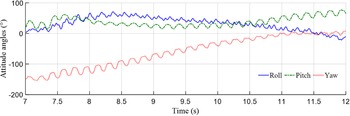
The design and electronics systems are further validated through a series of outdoor manual flights. These tests were conducted in an open sports field. The wing flapping motion is displayed in Figure 12, showing various positions within a stroke. The results demonstrate that the robot successfully achieves coupled flapping and folding motions: the wings fold during the upstroke and unfold during the downstroke. Typical flight data, recorded on an SD card, is presented in Figures 13–16, with the data covering the time interval from 7 to 12 s.
Composite image showcasing bat robot throughout a wingbeat cycle.

Acceleration data change with time.

Angular velocity data changes with time.

Attitude data changes with time.

Schematic diagram of the morphing mechanism: (a) The closed-loop MNKJ, (b) the closed-loop LMGF, and (c) the morphological parameters of bat robot.

Figures 13 and 14 illustrate the acceleration and angular velocity data, respectively. The x-axis represents the robot’s forward direction, while the z-axis points vertically upward along its back. The y-axis is determined according to the right-hand rule. The acceleration data in all three directions fluctuate within a certain range but remain relatively stable over time. The mean acceleration along the x-axis is 0.73 m/s2, indicating that the propulsion system provides consistent thrust. The z-axis mean acceleration is 0.51 m/s2, suggesting that the flight system facilitates smooth ascent.
The angular velocity across all three axes fluctuates around 0 rad/s, indicating stable flight performance. Figure 15 displays the recorded pitch, roll, and yaw angles. The data reveal that the aircraft successfully executed stable turns and level flight maneuvers. The attitude was initially recorded under the geodetic coordinate system and subsequently converted to a local coordinate system.
5. Conclusion
This study introduces a bio-inspired flapping-wing robotic platform that mimics the wingbeat kinematics of bats during level flight. Kinematic analysis shows that the robot achieves a dual-degree-of-freedom coupled motion: spanwise folding with a maximum fold ratio of 0.57, driven by a six-bar linkage mechanism, and chordwise flapping with amplitude of
 $38.5^{\circ}$
and a maximum frequency of f = 5 Hz, actuated by an asymmetric RSSR mechanism. Outdoor flight experiments demonstrate the robot’s ability to perform coordinated flapping and folding motions, with wing extension during the downstroke (maximum projected area, A = 0.42 m2) and retraction during the upstroke (maximum projected area, A = 0.24 m2). This robotic platform offers valuable insights and potential advancements in the fields of biomechanics and robotics.
Further work will investigate the aerodynamic characteristics of the flapping-wing robot. Wind tunnel experiments will be conducted to analyze airflow patterns during both flapping and folding phases. Furthermore, the integration of sensory feedback systems will be explored to enable real-time adaptation to dynamic flight conditions, enhancing the robot’s autonomy and flight efficiency.
Author contributions
Jing-Hu Li, conceptualization, writing – review & editing, writing the original draft, validation, software, investigation, data curation. Jun-Hao Qiu, writing – review & editing. Jing-Shan Zhao, conceptualization, writing – review & editing, supervision, project administration, methodology.
Financial support
This work was supported in part by the Basic Research Project Group of China and in part by the State Key Laboratory of Tribology, Tsinghua University.
Competing interests
The authors declare none.
Ethical approval
None.