Introduction
Information regarding the direction of the electric field oscillating in a plane perpendicular to the electromagnetic (EM) wave propagation path can be gleaned from the wave polarization [Reference Shukoor and Dey1]. In various real-time applications like polarization manipulation [Reference Zhao and Alù2], wavefront controlling [Reference Shukoor and Dey3], RCS and optical communication [Reference Cheng, Tian, Li, Deng, Yu and Chen4], controlling EM wave polarization plays a major role. EM polarization is generally altered by birefringent crystalline solids and liquids [Reference Strikwerda, Fan, Tao, Pilon, Zhang and Averitt5]. The weak anisotropic nature of available crystals necessitates much thicker components, so these converters become cumbersome and power-intensive. Compact hardware will become increasingly important as technology continues to shrink in size [Reference Shukoor, Dey and Dey6].
The research community has been bolstered by the advent of frequency selective surfaces (FSSs) technology [Reference Ranjbar and Grbic7] in the design of various 2D polarizers for cutting-edge wireless applications [Reference Mastro, Ettorre and Grbic8]. The development of FSS technology has piqued the interest of researchers in manipulating the amplitude, phase, and polarization states of electromagnetic waves [Reference Li9]. Reportedly, it is possible to control the propagation states of EM waves in both reflection and transmission modes across the spectrum [Reference Chen, Liu, Li, Cheng and Tian10]. Using square split rings as its basis, a small and efficient microwave linear–cross polarizer shows unity cross-pol reflectance in the 8.2–23 GHz frequency range [Reference Li9]. An ultrathin reflective polarizer was proposed with two bands, one for 4.40–5.30 GHz and the other for 9.45–13.60 GHz [Reference Huang, Yang, Zhang and Luo11]. Using an H-dipole configuration, a linear–cross and circular–circular reflective polarizer is demonstrated from 18 to 40 GHz entire K- and Ka-band range [Reference Shukoor, Dey and Koul12]. Broadband linear–cross conversion using asymmetric meanderline structures is demonstrated, and this design may keep its handedness even when subjected to a circularly polarized wave [Reference Shukoor, Dey, Koul, Poddar and Rohde13].
Unlike linear polarization (LP), circular polarization (CP) is unaffected by factors like Faraday rotation, multipath fading, and polarization mismatch [Reference Wang and Cheng14]. Linear-to-circular polarization converters (LCPCs) based on FSSs are now required to exploit all features, such as wideband, that are absent or difficult to implement with direct circularly-polarized (CP) antennas [Reference Tang, Mercader-Pellicer, Goussetis, Legay and Fonseca15] due to the limitations of CP antennas such as their narrow bandwidth, complex feeding, and polarization orthogonality. To control linear and circularly polarized waves in the frequency ranges of 4.40–5.30 GHz and 9.45–13.60 GHz, a metasurface based on concentric rectangular FSS is presented [Reference Huang, Yang, Zhang and Luo11]. A reflective linear–circular polarizer based on the Jerusalem cross, with an X-band bandwidth of 15% and an Axial Ratio (AR) of no more than or equal to 1 dB, is suggested for circular polarization conversion [Reference Wang, Kong, Ma and Cui16]. A two-dimensional double L-type resonator demonstrates multiband reflective type multi-polarization conversion [Reference Mao, Yang, He, Zheng and Zhou17]. A broadband linear-crossreflective polarizer that is both flexible and has an average polarization conversion ratio (PCR) of 85% is designed to operate from 11.3 to 20.2 GHz [Reference Wang, Kong, Yan, Xu, Liu, Mo and Liu18]. In Li et al. [Reference Li, Liu, Cheng, Chen and Tian19], a broadband ultrathin linear–circular polarizer is also invertible. This single-layered design can transform linearly polarized waves into circular ones and vice versa, thanks to the anisotropic optical resonances it induces. Different polarizers are introduced in the literature, from microwave [Reference Doumanis, Goussetis, Gómez-Tornero, Cahill and Fusco20] to optical regimes [Reference Chen, Liu, Li, Cheng and Tian10]. However, compact, highly miniaturized oblique angular stable multiband linear–cross and linear–circular conversions with CP in consecutive bands are desired for real-time sub-miniaturized applications.
Considering these factors, this work proposes a simple reflective polarizer that can execute LCPC in three frequency bands of 0.13 GHz (LHCP/RHCP in C-band), 2.64 GHz (RHCP/LHCP in X-band), and 21.21 GHz (LHCP/RHCP in Ku to Ka-bands). Furthermore, it is capable of linear-cross polarization conversion with bandwidths including 0.32 GHz (X-band), 1.63 GHz (Ku-band), and 2.33 GHz (Ka-band). Extremely small footprint unitcell area (0.478 $\lambda _L^2$/100) and considerable angular stability in transverse electric (TE) and transverse magnetic (TM) modes along with CP orthogonality.
This study suggests a unique linear–circular and linear–cross polarizer metasurface of a reflecting kind featuring two polarization layers. Section “Design of polarizer unitcell and simulation results” provides a comprehensive overview of the unitcell’s design and its simulation results. In Section “Proposed polarizer analysis using transfer matrix method”, the analysis for the multi-conversion is elaborated. The surface currents and electric field distributions are investigated and the reason for the multi-band conversion is detailed in Section “Surface current distribution analysis at resonant frequencies”. The prototype fabrication and comparison of the simulated and measured findings obtained using free-space measurement technique is demonstrated in Section “Polarization converter fabrication and free space measurement”. Finally, Section “Conclusion” concludes the work after observing a good match between the simulation and measurements.
Design of polarizer unitcell and simulation results
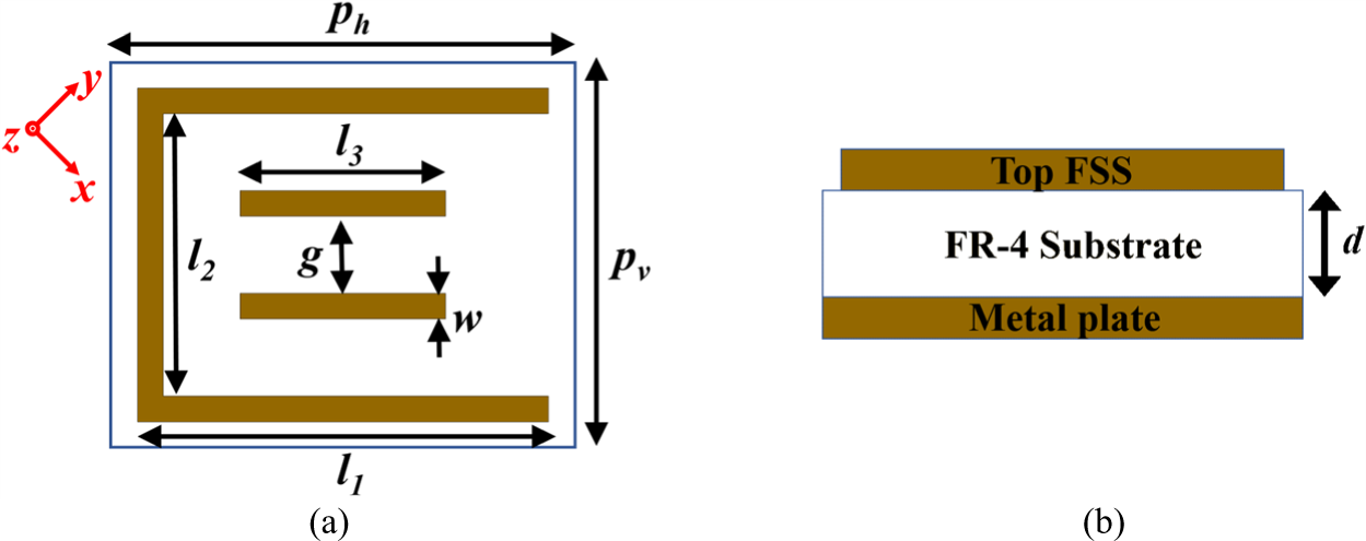
The proposed multiband polarizer’s unitcell design resembles a C-shaped patch with two horizontal dipoles, as shown in Fig. 1. As the dielectric spacer, commercially available FR-4 substrate and a 0.035 mm thin copper layer (with conductivity, σ = 5.8 × 10⁷ S/m) are used to serve the purpose. Due to its inherent wideband performance, the reflective type polarizer was chosen here. ANSYS HFSS, a finite element method (FEM) based solver, is used to simulate an infinite array and optimize the dimensions of the final unitcell for the desired performance by imposing the necessary periodic boundary conditions (PBCs). Final unitcell dimensions are: ph = 2.88 mm, pv = 2.4 mm, l1 = 2.56 mm, l2 = 1.76 mm, l 3 = 1.28 mm, w = 0.16 mm, g = 0.48 mm and d = 1 mm, as shown in Fig. 1.
(a) Top FSS, (b) side view of the proposed polarizer unitcell.

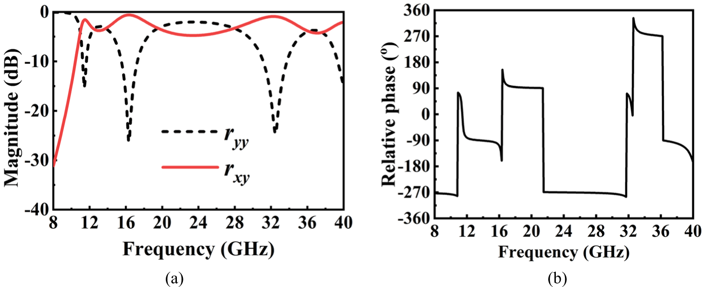
For the y-polarized wave incident on the proposed design, the co-pol ( ${r_{yy}} = \left| {{E_{yr}}} \right|/\left| {{E_{yi}}} \right|),\,$and the cross-pol (
 ${r_{xy}} = \left| {{E_{xr}}} \right|/\left| {{E_{yi}}} \right|$) reflectances are defined. The indices x and y are the field oscillating directions and the terms
 $\left| {{E_i}} \right|,\,\left| {{E_r}} \right|$ are the incident and reflected field components, respectively. The simulated magnitudes and phase results are shown in Fig. 2(a) and 2(b), respectively. The
 ${r_{yy}}$ component reaches a minimum of −15.34 dB, −26.24 dB, −24.67 dB, and 40.2 dB at 11.4 GHz, 16.3 GHz, 32.5 GHz, and 40.2 GHz, respectively.
Simulated (a) magnitudes and (b) phases of the co-pol and cross-pol reflectances of the proposed polarizer.

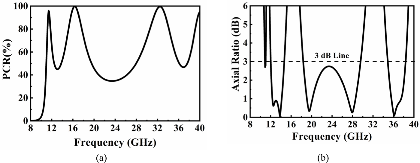
In comparison, the cross-pol component reaches almost 0 dB, demonstrating the perfect linear-cross polarization conversion over these ranges. The simulated PCR,  $PCR = r_{xy}^2/\left( {r_{xy}^2 + r_{yy}^2} \right)$ of the proposed design is shown in Fig. 3(a) and shows a minimum of 90% over 7.88–8.01 GHz, 9.01–11.65 GHz, 15.36–26.57 GHz, and 31.88–35.38 GHz with fractional bandwidth of 3.79%, 12.19%, and 7.92%. The design performance is not limited to linear-cross conversion; it also exhibits linear-circular conversion in other frequency ranges when both co-pol and cross-pol magnitudes are equal and relative phase shift of ± 90o. The linear-circular conversion efficiency is determined by AR, as calculated below [Reference Tang, Mercader-Pellicer, Goussetis, Legay and Fonseca15],
 \begin{equation}R = {\raise0.7ex\hbox{${{r_{xy}}}$} \!\mathord{\left/
{\vphantom {{{r_{xy}}} {{r_{yy}}}}}\right.}
\!\lower0.7ex\hbox{${{r_{yy}}}$}}\end{equation}
 \begin{equation}Schi,\,\chi = 0.5{\sin ^{ - 1}}\left( {\frac{{2R{\text{sin}}\left( {\Delta \phi } \right)}}{{1 + {R^2}}}} \right)\end{equation}
 \begin{equation}Axial\,Ratio,\,AR = |1/{\text{tan}}\left( \chi \right)\end{equation}
Simulated (a) PCR and (b) AR (dB) of performance of the proposed multiband reflective polarizer.

In this context, the shape of the polarization ellipse is described by Schi (χ). As illustrated in Fig. 3(b), the simulated AR remains within the range of ≤ 3 dB from 7.88 to 8.01 GHz, 9.01 to 11.65 GHz, 15.36 to 26.57 GHz, and 31.88 to 35.38 GHz with 1.64%, 25.56%, 53.47%, and 10.41% FBW, respectively.
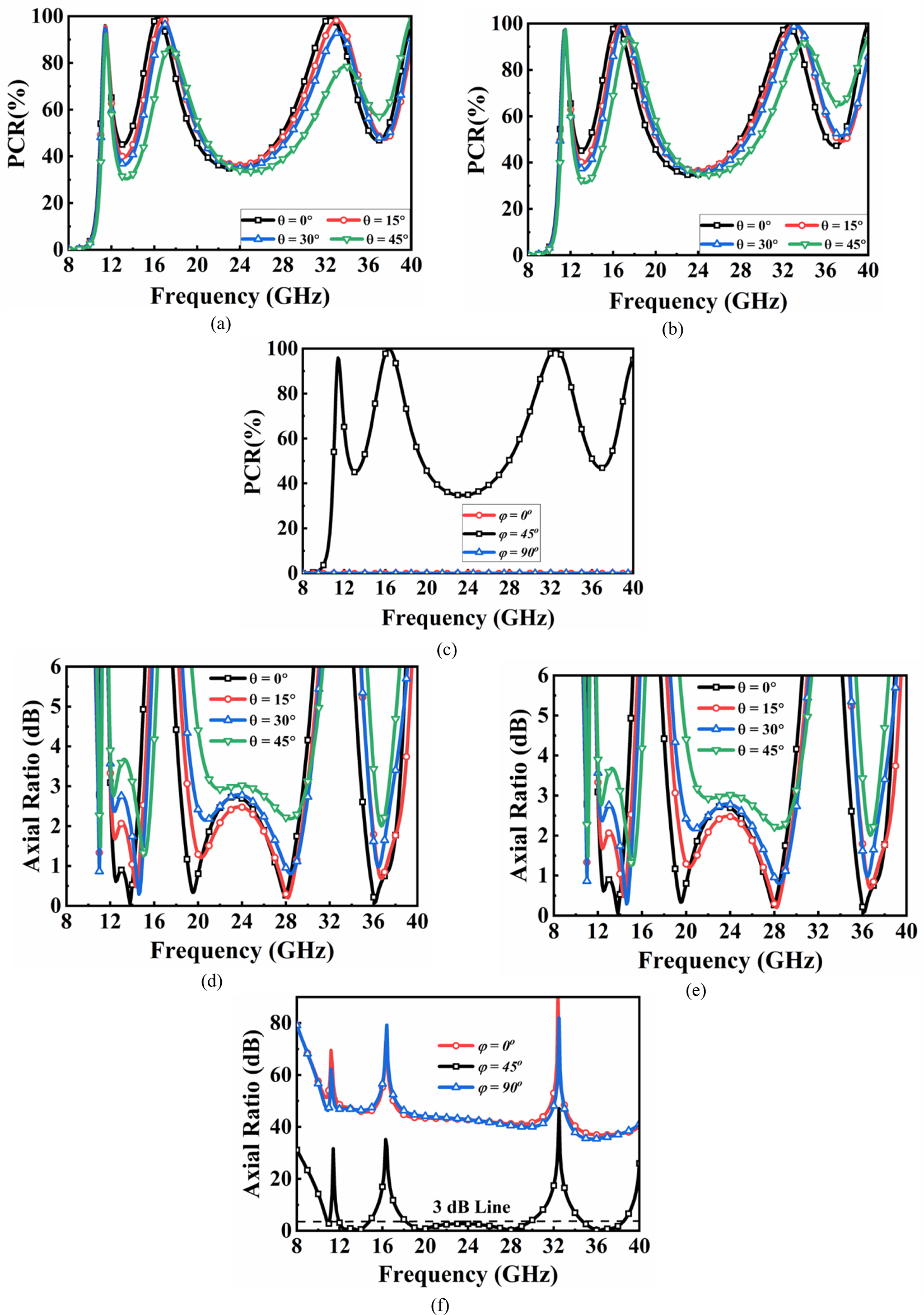
It is important to study how the performance of the transverse electric (TE) and transverse magnetic (TM) modes varies with the angle of incidence for both modes because, in real-world circumstances, the incoming wave on the metasurface is not typical. For both the TE and TM incidences, the performance of the polarizer is investigated under a range of oblique incident angles, from 0o to 45o, with 15o intervals. The fact that the input surface impedance perceived by the EM wave differs for various angles and modes is significant if the incidence angle changes. Figure 4 depicts the simulated PCR and AR for TE and TM incidences. It is clear that the response of the polarizer is stable up to 45o, and the performance degrades at angles above and beyond that due to the weak field couplings. As shown in Fig. 4, the suggested design shows a nearly steady response up to 45o, but performance drops at greater oblique angles because of grating lobes and weak field couplings. Reflectance phases provide a good explanation for the behavior of PCR at different oblique angles, even though PCR only takes reflectance magnitudes into account. PCR bandwidth decreases as the incidence angle is tilted from the normal. The amplitude and phase of the cross-pol component (rxy) remain almost constant, but the co-pol reflectance strongly depends on the incidence angle [Reference Wang, Kong, Ma and Cui16]. There is a phase difference between normal incidence as determined by Bragg’s diffraction and the additional path between the metasurface and the ground, which greatly affects the phase of co-pol reflectance. Although reflectance magnitudes are the focus of the PCR calculation, their behavior at larger oblique angles is better explained by considering the reflection phases. Since there is an extra path from the metasurface to the ground at higher angles, the co-pol reflectance has a different phase than normal incidence, as determined by Bragg’s diffraction [Reference Shukoor and Dey21],
 \begin{equation}\Delta \phi = {\phi _{oblique}} - {\phi _{normal}} = 2\sqrt {{{{\varepsilon }}_r}} kd\left( {\frac{1}{{\sqrt {1 - \frac{{si{n^2}\theta }}{{{{{\varepsilon }}_r}}}} }} - 1} \right)\end{equation}
Simulated PCR for the (a) TE, (b) TM for different elevation angles (θ), and (c) for different  $\varphi $. Simulated AR for the (a) TE, (b) TM for different elevation angles (θ), and (c) for different
 $\varphi $.

In this case, k is the wave vector in the dielectric medium, and θ is the angle the incident wave makes with respect to the normal polarizer. Not limited to that, the PCR and AR performance variation for different azimuthal incidences ( $\varphi $) varies from 0o to 90o in 45o steps are investigated. It is clear that, for
 $\varphi $ = 45o, the incident wave converts into cross and circular polarization. For the other incidences such as
 $\varphi $ = 0o, and 90o, the linearly y-polarized incidence wave will be reflected as it is without any polarization conversion, which is clear from Fig. 4(c) and 4(f). The next section discussed the conversion mechanism in detail.
Proposed polarizer analysis using transfer matrix method
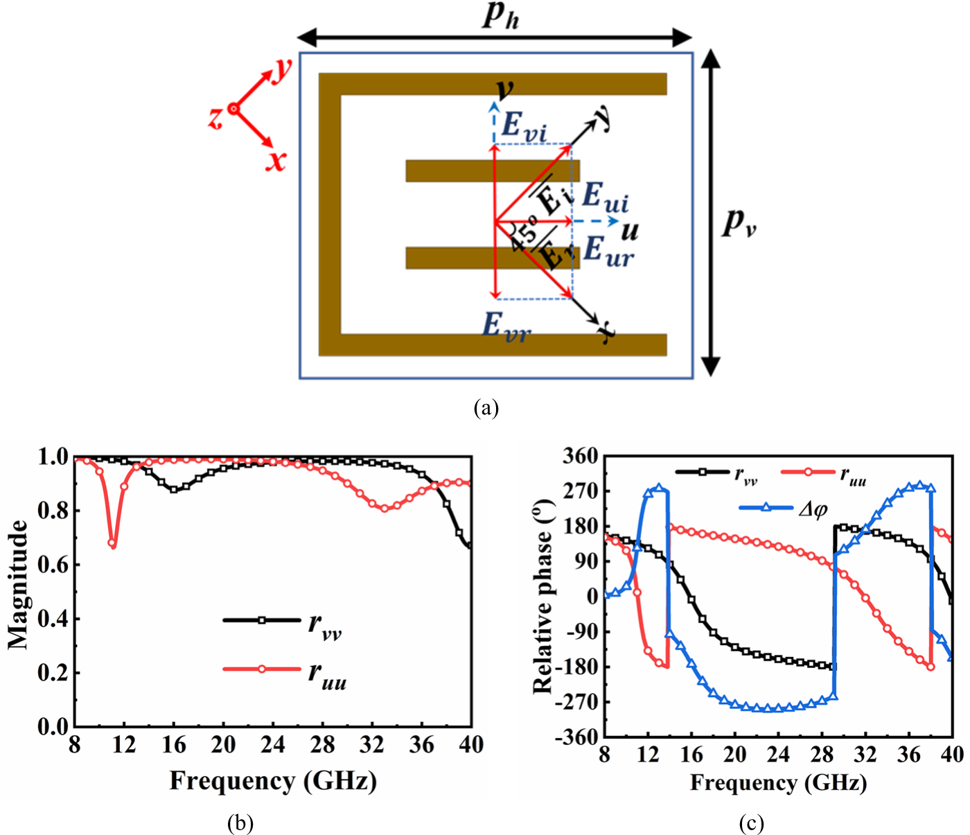
The underlying physical mechanism of polarization conversion is explained better by defining two axes, u- and v, as in Fig. 3(a). For a wave travelling in a negative z-axis direction, the incident electric field is given by  $\overrightarrow {{E_i}} = (E_i^u\tilde u + E_i^v\tilde v){e^{jkz}}$, where
 $E_i^u$, and
 $E_i^v\,$are the components along the uv-axes. Using TMM, the reflected field
 $\left[ {\overrightarrow {{E_r}} } \right] = \left[ {{R_{lin}}} \right]\left[ {\overrightarrow {{E_i}} } \right]$ is expressed as,
 \begin{equation}\left[ {\begin{array}{*{20}{c}}
{E_r^u} \\
{E_r^v}
\end{array}} \right] = \left[ {\begin{array}{*{20}{c}}
{{r_{uu}}}&{{r_{uv}}} \\
{{r_{vu}}}&{{r_{vv}}}
\end{array}} \right]\left[ {\begin{array}{*{20}{c}}
{E_i^u} \\
{E_i^v}
\end{array}} \right]\end{equation}
The impact of the cross-pol reflectance is negligible because the unitcell design is symmetric about uv-axes. Then the reflected filed component would be summarized as
 \begin{equation}\overrightarrow {{E_r}} = ({r_{uu}}E_i^u\tilde u + {r_{vv}}E_i^v\tilde v){e^{ - jkz}}\end{equation}
Fig. 5(b) and 5(c) show the simulated amplitudes and phases of the co-pol reflectances  ${r_{uu}}$ and
 ${r_{vv}}$. It seems clear that the magnitudes of
 ${r_{uu}}$ and
 ${r_{vv}}$ are nearly unity over the band, with a small dip at frequencies of 11.19 GHz, 16.11 GHz, and 33.07 GHz. The mode at 11.19 GHz is more dominant (with a higher Q-factor) among others. Then,
 ${r_{uu}} = {{\text{e}}^{j{\varphi _u}}}$,
 ${r_{vv}} = {{\text{e}}^{j{\varphi _v}}}$ and
 $\Delta \varphi = {\varphi _u} - {\varphi _v}$, if the substrate loss is disregarded. Table 1 compiles all the possible
 ${r_{uu}}\,$and
 ${r_{vv}}\,$magnitude and phase combinations, which require different polarization conversions [Reference Lin22].
(a) Schematic of the polarizer unitcell including uv-axis. Simulated (b) magnitudes of ruu and rvv, (c) relative phase (Δφ).

Summary of polarization conversion for different magnitudes and relative phases

It is also important to know the reason behind the wideband polarization conversion, which would be determined by understanding the surface current distribution analysis, which is detailed in the next section.
Surface current distribution analysis at resonant frequencies
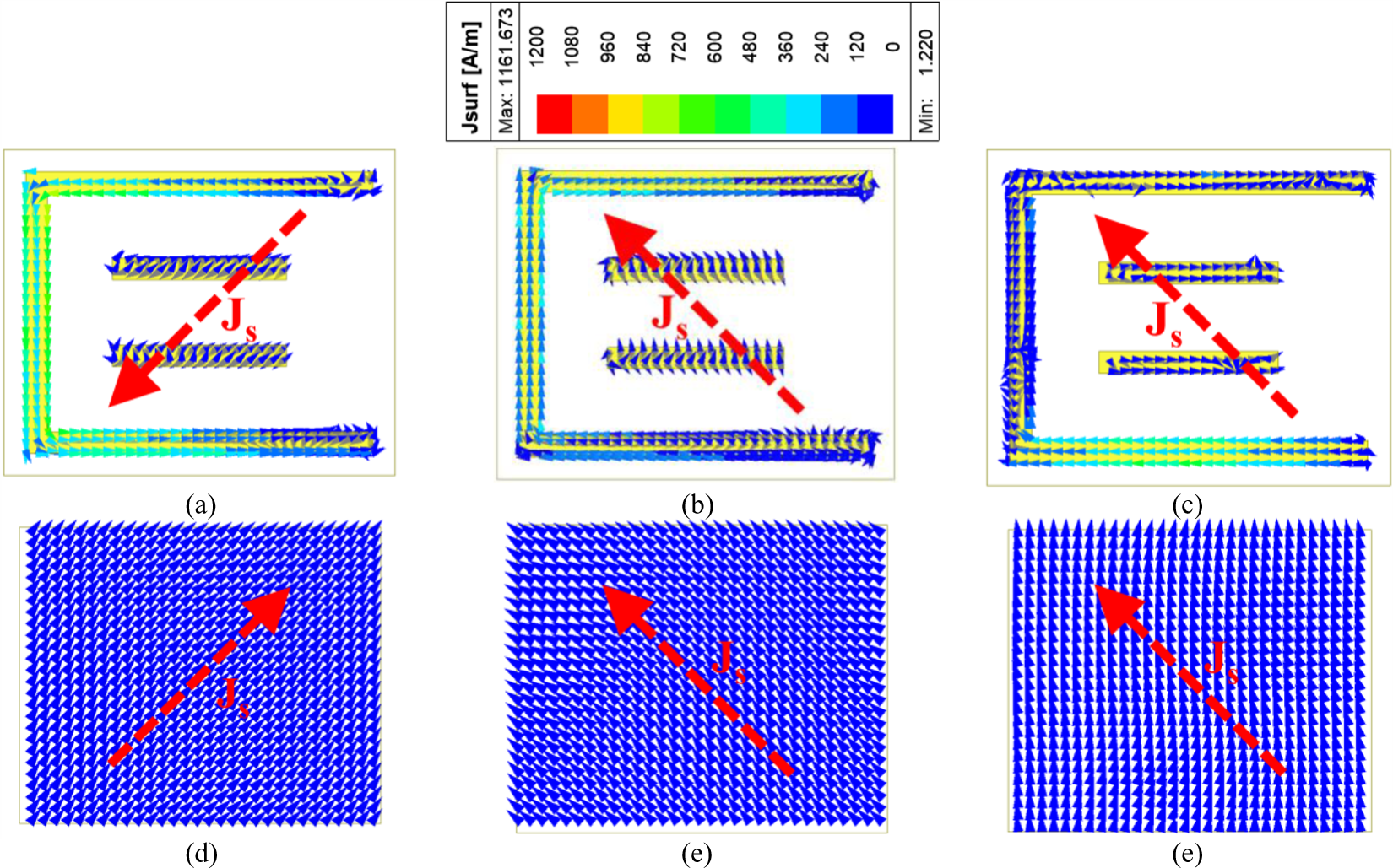
In this section, the surface current distribution analysis of the top FSS patch and the ground plane are investigated at different resonant frequencies, 11.4 GHz, 16.3 GHz, and 32.5 GHz (see Fig. 2(a)), as depicted in Fig. 6. When an EM incident on polarizer metasurface, the incident electric and magnetic fields couples the metallic portion induces surface currents and generates multiple plasmonic resonances. From Fig. 6(a) and 6(d), it seems clear that the surface currents of the top FSS and bottom ground plane are out of phase (anti-parallel), resulting in magnetic or dielectric resonance. For the incident frequency of 16.3 GHz, the surface currents of the top FSS and ground are in parallel, resembling electrical resonance. In addition to that, there is hybrid resonance mixed with both electric and magnetic ones, where the direction of the surface current is random. Hence, from the above analysis, it can be clear that multiple plasmonic resonances are solely responsible for multi-polarization conversion over the wideband operating range.
Simulated surface current distributions for the top FSS at (a) 11.4 GHz, (b) 16.3 GHz, (c) 32.5 GHz, and for the ground at (d) 11.4 GHz, (e) 16.3 GHz, (f) 32.5 GHz.

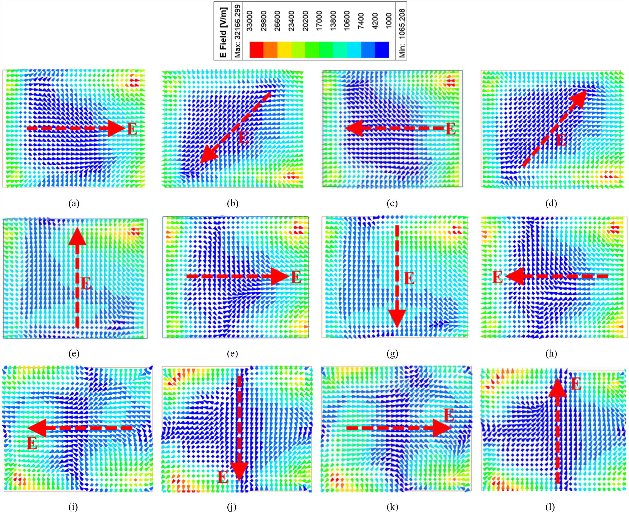
Simulated electric field of the reflected wave from the polarizer for 13.78 GHz incident wave at incident phase (a) ϕ = 0o, (b) ϕ = 90o, (c) ϕ = 180o, (d) ϕ = 270o. For 19.52 GHz incident wave at incident phase (e) ϕ = 0o, (f) ϕ = 90o, (g) ϕ = 180o, (h) ϕ = 270o. For 36.12 GHz incident wave at incident phase (i) ϕ = 0o, (j) ϕ = 90o, (k) ϕ = 180o, (l) ϕ = 270o.

In addition to linear–cross, the proposed design also converts linear-circular conversion in more than one frequency band, as shown in Fig. 3(b). The handedness of the CP decides whether the reflected wave is right-handed or left-handed. To demonstrate the CP handedness, the near field of the reflected wave is depicted at frequencies, i.e. 13.78 GHz, 19.52 GHz, and 36.12 GHz, where the AR is a minimum. At 13.78 GHz, the electric field rotation resembles clockwise sense, also called left-hand CP, which is also depicted from the relative of +90o, as in Fig. 2(b). The same analysis holds for the frequency 16.3 GHz, while the electric field rotation is an anti-clockwise sense of rotation or right-handed CP. The proposed design is fabricated, and a performance comparison is detailed in the next section.
Polarization converter fabrication and free-space measurement
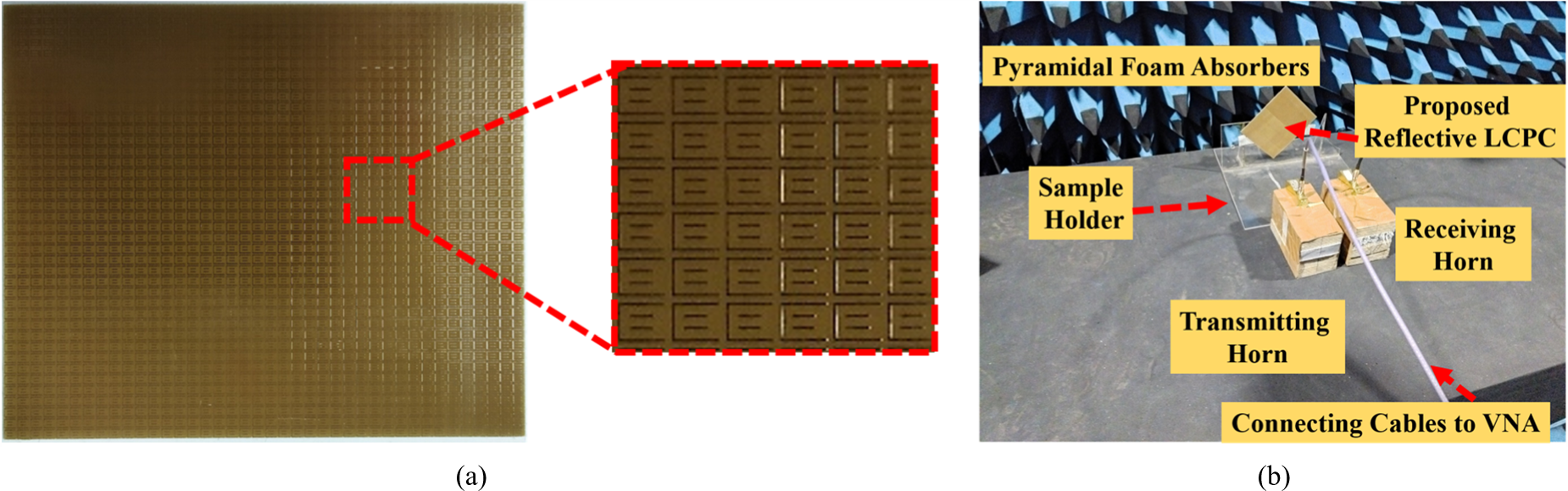
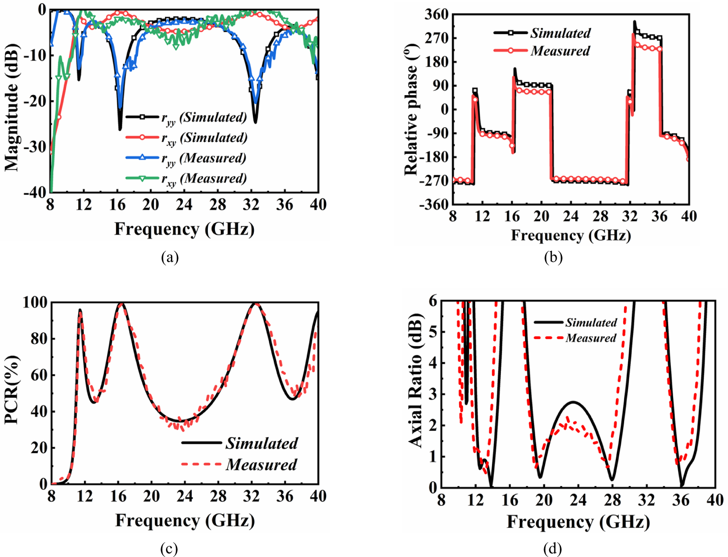
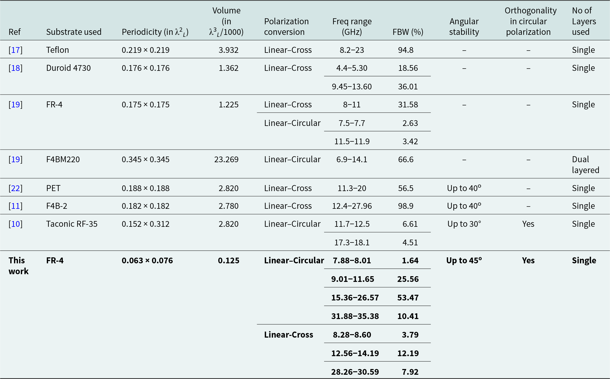
The 40 × 40 array (115.2 × 96 mm2) prototype is manufactured using standard printed circuit board (PCB) technology for verification of the simulated findings (see Fig. 8(a)). The free-space measurement technique is adopted in this work to verify simulation findings, as shown in Fig. 4(b). The Keysight Power Network Analyser (PNA) N5224B span the frequency range of 10 MHz to 43.5 GHz are connected to a pair of high-gain horn antennas (one for transmission and one for reception) by high-quality RF connection probes. The sample is positioned at 5o with respect to the horn antennas and is placed in the far-field zone (see Fig. 8(b)). These antennas were placed at an angle of 5o to each other to maximize the power incident on the transmitter and reflected on the receiver under normal incidence. A perfect electric conductor (PEC) of prototype size is used to calibrate the PNA. For the cross-pol measurement, the receiver antenna is skewed by 90o relative to the transmitter. Antennas are aligned in the same polarization plane for the co-pol measurement, with the resulting response of both the reflectances shown in Fig. 9(a). Then, the measured PCR and AR are depicted in Fig. 9(c) and 9(d), respectively. The measured outcomes are in close proximity to the simulated ones. To the best of the author's knowledge, the proposed design is extremely thin and illustrates the multi-polarization conversion between linear to circular and linear to cross conversion. Its design’s qualities make it work in sub-miniaturized, real-time applications. The proposed polarizer’s superior performance will become evident compared to other recently announced state-of-the-art designs (see Table 2).
(a) Fabricated 40 × 40 prototype array of the proposed polarizer. (b) Free-space measurement setup.

Comparison of the simulated vs measured reflectances (a) magnitude, (b) relative phases, (c) PCR, and (d) AR (dB).

State-of-the-art performance comparison of the proposed design with other recently reported reflective-type polarizers

Conclusion
In order to accommodate a variety of C-Ka uses, this study presents a polarization converter that combines linear–circular and linear–cross in reflection mode. The design features a printed resonant patch attached to a grounded FR-4 substrate. When it comes to oblique TE and TM situations, performance is consistent. Wideband features for various polarization conversions can be attributed to many plasmonic resonances. The innovative features of this structure include orthogonal circular rotation in consecutive bands, highly miniaturized unitcell architecture with multiple polarization conversions over a variety of frequency ranges, and improved angular stability. These perks, to the best of the authors’ understanding, qualify the layout for use in real-time applications.
Acknowledgement
The authors would like to thank the Science and Engineering Research Board (SERB) for supporting the work under the National Postdoctoral Fellowship PDF/2023/002911.
Author contributions
A.S derived the theory and K.R. and S.D. contributed to analyzing data and reaching conclusions, and in writing the paper.
Competing interests
The authors report no conflict of interest.

Dr. Mohammad Abdul Shukoor (Member, IEEE) received a PhD in 2023 from Electrical Engineering, IIT Palakkad, Kerala, India- 678557. Abdul has done his M.Tech Degree in Radar & Microwave Engineering from Andhra University and a bachelor's in Electronics and Communication from Acharya Nagarjuna University in 2016 and 2013, respectively. Dr. Abdul is working as a Postdoctoral Fellow in the Department of ECE, IIT Roorkee, with Prof. Karun Rawat. His current research interests include metamaterial-based absorbers, FSS, and polarization converters, and now he has extended his journey towards Active antennas, Active Reconfigurable Intelligent Surfaces (RISs) and RF Power Amplifiers. He has published more than 50 research articles and six Indian, two US patents (1 granted). In addition, Dr. Abdul was the recipient of the Best Paper Awards in IEEE Conferences like International IoT, Electronics and Mechatronics Conference, Vancouver, BC, Canada, in 2020, WAMS 2022, and MAC 2024.

Sukomal Dey (Senior Member, IEEE) received the B.Tech degree in Electronics and Communication Engineering at the West Bengal University ofTechnology, Kolkata, India, in 2006, an M.Tech degree in Mechatronics Engineering at the Indian Institute of Engineering Science and Technology, Shibpur, India, and did his M.Tech dissertation (one year) at Central Electronics Engineering Research Institute (CEERI-CSIR), Pilani, India, in 2009. Dr. Dey obtained the Ph.D. degree from the Centre for Applied Research in Electronics (CARE), Indian Institute of Technology Delhi in July, 2015. From, August, 2015 to July, 2016 he was working as a project scientist in Industrial Research and Development centre, IIT Delhi. He also worked on a collaborative research project supported by Synergy Microwave Corp., NJ, USA during the same period. From August, 2016 to June-2018, he was working in the Radio Frequency Microsystem Lab (RFML), National Tsing Hua University, Taiwan, as a Post doctorate Research Fellow. Presently, Dr. Dey is working as an Associate Professor at Department of Electrical Engineering, Indian Institute of Technology Palakkad, Kerala. Dr. Dey is a recipient of the Postgraduate Student Award from the Institute of Smart Structure and System, Bangalore, in 2012, Best Industry Relevant PhD Thesis Award from the Foundation for Innovation in Technology Transfer, IIT Delhi in 2016, Postdoctoral Fellow Scholarships from the Ministry of Science and Technology, Taiwan in 2016 and 2017, respectively, Early Career Research Award from the Science and Engineering Research Board (SERB), Government of India in 2019 and Smt. Ranjana Pal Memorial Award (2021) from the Institution of Electronics and Communication Engineers. He has authored/co-authored more than 80 research papers, 2 state-of-the art books, 2 book chapters and filed 11 patents. His research interests include: Electromagnetic metamaterial structures, frequency selective surfaces, microwave imaging, microwave integrated circuits including antennas and RFMEMS.