1. Introduction
The Global Navigation Satellite System (GNSS) has been widely used to provide high-precision and high-integrity services for many aeronautical applications. GNSS has become the primary means of navigation in aeronautics and will continue with the advent of multifrequency, multiconstellation services. However, because of its low signal strength, GNSS is vulnerable to interference. Therefore, there is a need to provide A-PNT services for use during a GNSS outage. Such solutions are being investigated to provide civil aviation airborne users with required navigation performance (RNP) services from RNP 1 for a short to midterm solution down to RNP 0⋅3 in the long term, in particular within the Single European Sky ATM Research (SESAR) Solution PJ.14-W2-81. Providing an alternate time reference for ground communications, navigation, surveillance/air traffic management (CNS/ATM) systems is out of the scope of the project (Vitan et al., Reference Vitan, Berz, Saini, Arethens, Belabbas and Hotmar2018).
While there are several new technologies proposed to support an A-PNT solution, DME/DME navigation is a primary candidate in the midterm and a potential long-term candidate, thanks to the high adoption rate in both ground and airborne segments. Current work mainly focuses on the use of DME/DME as the main reversionary capability to maintain safety and continuity of operations during a GNSS outage (Lilley and Erikson, Reference Lilley and Erikson2012; Jalloul et al., Reference Jalloul, Ajib, Yeste-Ojeda, Landry and Thibeault2014). Two facts drive the community to consider using multi-DMEs in this field, in which the number of available DME beacons exceeds the required two, with high coverage. Firstly, when there is only one pair of DMEs used for aircraft location estimation, the angle between the line-of-sight vectors to the stations must lie within the 30°–150° range (Ostroumov, Reference Ostroumov2016). Secondly, many investigations have indicated that the accuracy and integrity of positioning are improved using the multi-DMEs approach. For example, up to 20 DMEs are visible within 40NM of CDG airport when the aircraft is above 6000 ft altitude, making it possible to use multi-DMEs positioning. Taking advantage of these existing DME measurements redundancy, the multi-DMEs positioning algorithm derives a bounding of DME positioning error that can support the 10−5/h on-board performance monitoring and alerting (OBPMA) integrity requirements for RNP 1 (Vitan et al., Reference Vitan, Berz, Saini, Arethens, Belabbas and Hotmar2018).
Previous work (Vitan et al., Reference Vitan, Berz and Solomina2015) assessed the DME performance of both DME/DME and multi-DMEs, showing that the multi-DMEs solution has clear benefits. However, it is unlikely to provide similar benefits at low altitudes, due to the less-abundant ranging sources. To support the performance for A-PNT, it is also worthwhile to consider the fusion of existing sensors. A barometric altimeter can be integrated to improve the performance of integrity monitoring and accuracy, especially vertical accuracy (Ali and Taib, Reference Ali and Taib2019; Liang et al., Reference Liang, Milner, Macabiau and Estival2020). In a ground-based A-PNT, such as is the case for multi-DMEs, the geometrical configuration of the ranging sources on the ground generally leads to a high vertical dilution of precision (VDOP). Because of the high VDOP, the vertical component of the position must be obtained by other means. Since air data systems are installed in all certified aircraft, the barometric altimeter is the obvious source of information that can be used to compensate in the case of poor geometry (Berz et al., Reference Berz, Vitan and Skyrda2013; Nossek et al., Reference Nossek, Dambeck and Meurer2015; Battista et al., Reference Battista, Kumar, Osechas and Belabbas2018).
It is also worthwhile considering the tactical air navigation (TACAN) system as an additional means of A-PNT. TACAN is the military DME equivalent, and thus has similar operations to DME (Ramsayer, Reference Ramsayer1970). When TACAN is used for area navigation (RNAV) purposes, the related station information is listed in the civil aeronautical information publications (AIPs). However, there are few TACAN stations available for civil applications, insufficient alone for A-PNT. TACAN can provide additional beacons to reduce the dependence on the number of DME stations and improve the geometric performance of the multi-DMEs.
In this paper, the accuracy and integrity monitoring performance of multi-DMEs over Europe is evaluated. The accuracy of the positioning solution depends on both the accuracy of DME ranging measurements and the geometry of ground to air line-of-sight vectors. In this paper, we consider three possible DME ranging measurement performance values: $2{\sigma _{DME}} = 0 {\cdot} 2\,NM$ (ICAO, 2006), $2{\sigma _{DME}} = 0 {\cdot} 1\, NM$
 (Berz and Bredemeyer, Reference Berz and Bredemeyer2008) and $2{\sigma _{DME}} = 0 {\cdot} 06\, NM$
 (Lo et al., Reference Lo, Chen, Enge, Peterson, Erikson and Lilley2013). The horizontal figure of merit (HFOM), which represents a conservative predicted 95% limit on the horizontal error, is used for the predicted position accuracy bound (RTCA DO-384, 2020). An acceptable bound of HFOM is expressed with the horizontal geometry of the ground DME stations. The horizontal geometry can be described by the horizontal dilution of precision (HDOP) coefficients. However, if the integration of additional sensors (altimeter and/or TACAN) is employed, the different systems have different measurement accuracies, which will lead to different weights in the combined solution. In this case the HDOP may not accurately describe the impact of geometry on performance, and a weighted form is needed. Integrity monitoring is required when designing a navigation system to meet predefined integrity requirements, and it is needed operationally to inform the user whether a mission should be pursued or aborted. In the domain of GNSS, receiver autonomous integrity monitoring (RAIM) is currently used as a means of fault detection (FD) and exclusion. Two main implementations of RAIM have been widely used, which are solution separation (SS) and chi-squared residual based (RB) (Joerger et al., Reference Joerger, Chan and Pervan2014). Receiver manufacturers who used RB approaches in their GPS-based RAIM products may prefer implementing RB methods in multi-DMEs to ensure compatibility with legacy products (Zhao et al., Reference Zhao, Joerger, Liang, Pervan and Liu2020). An FD integrity monitoring mechanism based on FD RB RAIM applied to multi-DMEs measurements is developed in this paper to meet the integrity risk for certain faulty states within the multi-DMEs A-PNT framework. Integrity monitoring includes both the FD function and quantifying the impact of undetected faults on estimation errors.
This paper is organised as follows: In Section 2, the performance requirements including accuracy and integrity are described. Then, the model of multi-DMEs is presented in Section 3. Meanwhile, the performance monitoring methods of accuracy and integrity are discussed in order to achieve the specified RNP requirement. The HFOM for a DME-only solution and an aided solution is analysed. The integrity monitoring solution based on RB FD method is also introduced for all systems. Then, the baro-aided multi-DMEs method and the multi-DME plus TACAN combination method are proposed. Next, test results and performance analyses are presented. A case study on a specific airport is also conducted to evaluate the performance around an airport. Finally, a summary and discussions are given.
2. Performance requirements
2.1. Accuracy
To predict the performance of the proposed A-PNT system, it is fundamental to consider the RNP accuracy and integrity-performance monitoring requirements. The RNP accuracy requirement is such that each aircraft operating in RNP airspace shall have a total system error (TSE) along the lateral track directions that is less than the RNP value 95% of the flying time (RTCA DO-384, 2020). TSE is a three-dimentional vector that consists of the sum of the navigation system error (NSE) vector, the flight technical error (FTE) and the path definition error (PDE), such that

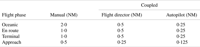
The FTE is a path-steering error which depends on the flight control method. Assumed horizontal FTE 95% bound values are present in Table 1 (RTCA DO208, 1991). The PDE is the error associated with route waypoints and is usually considered negligible. The NSE is also called a sensor-position estimation error, and it results from the positioning system. The distribution of these errors is assumed to be independent, zero-mean and Gaussian.
Horizontal FTE Assumptions (95% probability)

To obtain horizontal accuracy requirement for RNP, we should consider the situation where the horizontal error distribution is elliptical and skewed relative to north (or east). Given two (major and minor axis) Eigenvalues of the covariance matrix P of the horizontal components of any of the 2D error vectors FTE, NSE or PDE are $\sigma _1^2$ and $\sigma _2^2$
 . Since ${p_{11}} + {p_{22}} = \sigma _1^2 + \sigma _2^2$
 and if $\sigma _2^2 \ll \sigma _1^2$
 , then $\sigma _1^2 \approx {p_{11}} + {p_{22}}$
 . Therefore, the distribution of TSE is also assumed to be bounded with a Gaussian distribution with a standard deviation equal to the root sum square of the dominating standard deviations of the horizontal projection each of these three errors (PBN manual, 2008):

In this paper, we select FTE as 0⋅25 NM with autopilot assumed to be on, then we could have 95% NSE accuracy requirement of 0⋅97 NM for RNP 1 and 95% NSE accuracy requirement of 0⋅17 NM for RNP 0⋅3.
2.2. Continuity
For RNP operations, in line with GNSS RAIM, the global requirement for loss of continuity $({C_{req}})$ is set at 10−5/h. Loss of continuity events for the FD multi-DMEs solution are multi-DMEs RAIM false alerts. DME service loss of continuity due to ground transponder outage, propagation or interference problems. A false alert (FA) is defined as the indication of a failure when a positioning failure has not occurred. The false alert probability $({P_{fa}})$
 represents the probability of any FA event over an exposure interval. However, as indicated, loss of continuity events may also be due to ground transponder, propagation or interference continuity issues. Assuming the entire continuity budget $({{C_{req}}} )$
 of 10−5/h is allocated to FD RAIM FAs, we need a maximum tolerable ${P_{fa}} = {10^{ - 8}}$
 from Equation (3) (Milner et al., Reference Milner, Pervan, Blanch and Joerger2020). Furthermore, ensuring continuity may require the implementation of an FDE algorithm, and not solely FD algorithm as is considered in this paper, future work will address FDE RAIM for DME. Assuming the entire continuity budget is allocated to FD RAIM FAs, accounting for the temporal decorrelation of these events over the operation (in particular assuming temporal decorrelation of DME range errors over the operation), a bound on RAIM FD FA probability may be defined as:

where
$n$
 is the number of TTA periods per exposure window;
${T_e}$
is the operation exposure time, which is 3600 s for RNP;${T_a}$
is the required time to alert, which is 10 s for RNP.


2.3. Integrity
The integrity requirement states that the probability that the TSE of each aircraft operating in RNP airspace exceeds the lateral containment limit without annunciation shall be less than 10−5 per flight hour. The OBPM provides the pilot with an alert when the probability that TSE exceeds 2xRNP is greater than 10−5 per flight hour (AC 20-138D, 2014). Nominally, the horizontal protection level (HPL) should be less than 1 NM for RNP 1 and less than 0⋅3 NM for RNP 0⋅3 (EU-US Cooperation, 2015).
A missed detection (MD) is defined to occur when the FD algorithm does not detect a positioning failure. In this paper, in order to derive a requirement on the probability of MD from the global requirement, we consider that in most regions there are generally eight visible DME stations at most, and that any can lead to a failed range measurement. Furthermore, the performance does not significantly improve with more than eight visible DME stations. Thus, we assume the situation with eight visible DME stations will be the worst case for integrity allocation, as given by Equation (4). The correlation time of the DME range errors is unknown at this stage, and further research on this topic is required. Pending further research on time correlation of events, an upper bound on the number of equivalent samples for continuity has been chosen in Section 2.2. Considering the time correlation of events will be mandatory for the final performance evaluation of multi-DMEs navigation. For the current paper, in absence of information on DME ranging error time correlation, for prediction of missed detection performance of FD RAIM, no account of number of equivalent samples for integrity is made. The probability of missed detection $({P_{md}})$ is then determined to be 5 × 10⁻⁵ from Equation (4) where we set N as 8:

where
${P_{HMI\_req}}$
is the global integrity risk requirement of 10−7 /h;${P_{fail}}$
is the probability of ranging integrity failure at a single DME station;$N$
is number of DME stations considered;MTBF is the Mean Time Between Failures, which should be less than 4000 h (EUROCAE ED-57, 1992).


Only single-station fault is considered on the assumption that the likelihood of undetected multiple DME stations error is negligible. Common cause errors may also be neglected due to the independent nature of the DME station operations.
3. Multi-DMEs
In the multi-DMEs positioning case, the positioning solution is computed using all available ranges. The algorithm is very similar to the GNSS solution algorithm, while the equations do not include the clock offset variable due to the two-way ranging of DME. The observation equation of multi-DMEs is:

where:
${z_{DMEi}}({i = 1 \ldots m} )$
is the residual slant range measurement, i.e., the slant range measurement from the DME station to the computed user position minus the true slant range distance to the true user position;${\boldsymbol{H}_{DMEi}} = \left[\begin{smallmatrix}n_{DMEi}\\ {{e_{DMEi}}}\\ {{u_{DMEi}}} \end{smallmatrix}\right]^{T}$
$({i = 1 \ldots m} )$ is the observation matrix with co-ordinates in the local east-north-up reference frame;$\boldsymbol{x}$
is the 3 × 1 user position vector in the local reference frame centered on the true user position;${\boldsymbol{f}_{DME}}$
is the m × 1 fault vector;${\boldsymbol{\delta }_{DME}}$
is the measurement error vector;$m$
is the number of visible DME stations.


To obtain the 3D position of an aircraft, there should be at least three measurements from DME stations in view of the aircraft. Considering the need for redundancy in RAIM-based integrity monitoring to achieve FD, a minimum of four DME stations is required.
4. Performance monitoring
4.1. Accuracy monitoring
The predicted position accuracy bound is typically the HFOM, which represents a conservative predicted 95% limit on the horizontal error. An acceptable bound of HFOM is expressed as:

Assuming the ranging measurement error of each DME is bounded with an identical distribution, since $HDOP.{\sigma _{DME}} = \sqrt {{p_{11}} + {p_{22}}}$ , we can get the position accuracy bound HFOM:

${\sigma _{DME}}$ is the standard deviation of each DME measurement error.
The positioning accuracy monitoring performance is evaluated by comparing HFOM. If the HFOM is below the threshold of 95% NSE accuracy requirement, we will say the RNP 1 accuracy requirement is met.
There is no RNP requirement for the vertical positioning performance. Also, the value of the standard deviation of FTE in the vertical dimension has not been established. Therefore, we cannot determine the vertical accuracy requirement. However, assuming the range measurement error of each DME is bounded with an identical distribution, the 95% accuracy bound of positioning by DMEs on vertical axis could be predicted to be as:

4.2. Integrity monitoring
Integrity monitoring not only detects faults but also must evaluate the integrity risk, or alternatively, a protection level, which is an integrity-bound on the position-estimate error. The DME ground station is responsible for monitoring the DME signals and reacting in a timely manner if any fault is detected. The fault detection is performed using the RB fault detection method that tests the consistency between measurements.
The protection level which bounds the integrity risk is given by (Brown and Chin, Reference Brown and Chin1998):

where $Hslope = \frac{{\sqrt {S_{1i}^2 + S_{2i}^2} {\sigma _i}}}{{\sqrt {1 - {P_{ii}}} }}$ is the horizontal position error per test threshold slope for each ranging measurement, $\boldsymbol{P} = {\boldsymbol{H}_{DME}}{({{\boldsymbol{H}_{DME}}^{\boldsymbol{T}}{\boldsymbol{H}_{DME}}} )^{ - 1}}{\boldsymbol{H}_{DME}}^{\boldsymbol{T}}$
 , $\boldsymbol{S} = {({{\boldsymbol{H}_{DME}}^{\boldsymbol{T}}{\boldsymbol{H}_{DME}}} )^{ - 1}}{\boldsymbol{H}_{DME}}^{\boldsymbol{T}}$
 , ${\sigma _i}$
 is the standard deviation of ith measurement error; ${\lambda _u}$
 is non centrality parameter, a conservative upper-confidence bound when the threshold test is passed is defined by the solution ${\lambda _u}$
 to $\int_0^{threshold} {{f_{({m - 3} ),{\lambda _u}\textrm{\; }}}(x )dx = 1 - {P_{md}}}; f(x)$
 is a probability density of the test statistic x, and x follows non-central chi-squared distribution with m-3 degrees of freedom; $k({{P_{md}}} )$
 is the number of standard deviations corresponding to the specified ${P_{md}}$
 ; and $HRMS = \sqrt {{{[{{{({{\boldsymbol{H}_{DME}}^T{\boldsymbol{H}_{DME}}} )}^{ - 1}}} ]}_{1\; 1}} + {{[{{{({{\boldsymbol{H}_{DME}}^T{\boldsymbol{H}_{DME}}} )}^{ - 1}}} ]}_{2\; 2}}}$
 is the horizontal confidence.
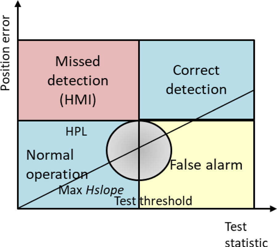
In the presence of a failure, the impact of the fault is a bias on the position error and test statistic, which in the absence of noise would lie on the corresponding $Hslope$ for the failed station (see Figure 1). How far along the slope line depends on the magnitude of the bias. In the presence of measurement noise, ellipses centred at the point on the slope line due to the fault bias represent the statistical distribution of possible position error; test statistic couplets. A valid integrity algorithm should alert the pilot to this failure in due time after the horizontal error exceeds the desired HPL.
The distribution of horizontal errors in the case of a failed station

5. Baro-aided multi-DMEs
The barometric altimeter measurement equation is:

where:
${h_{baro}}$
is the barometric altitude measurement vector;${h_{real}}$
is the true height;$\Delta h$
is the barometric altimeter measurement deviation;${\delta _{baro}}$
is the barometric altimeter measurement error, and we assume that the error follows Gaussian distribution.


The barometer is a complementary ranging source to DME. After a coordinate transformation, the barometric observation equation is extended to the DME observation equation. We assume there is no barometric measurement fault:

The inclusion of the barometric altimeter is beneficial to the estimation due to higher accuracy of the observation and the increased redundancy. Since the DME stations and barometer are weighted differently, we can no longer separate the expected positioning errors into a geometrical factor (DOP) and a user ranging accuracy that is common to all stations. The weighted form should then be used to describe the vertical accuracy instead of Equation (8).

where

${\sigma _{baro}}$ is the standard deviation of barometric altimeter measurement error.
Because the last row of $\bar{\boldsymbol{W}}$ is based on the accuracy of barometer, which is much superior to that of DME slant range measurements, accuracy performance will be improved.
With the aid of barometric altimeter, we can obtain the new expression of HPL:

where the horizontal position error per test threshold slope $\overline {Hslope} = \frac{{\sqrt {\bar{S}_{1i}^2 + \bar{S}_{2i}^2} {\sigma _i}}}{{\sqrt {1 - {{\bar{P}}_{ii}}} }}$ and the horizontal confidence $\overline {HRMS} = \sqrt {{{[{{{({{{\bar{\boldsymbol{H}}}^T}\boldsymbol{\bar{W}\bar{H}}} )}^{ - 1}}} ]}_{1\; 1}} + {{[{{{({{{\bar{\boldsymbol{H}}}^T}\boldsymbol{\bar{W}\bar{H}}} )}^{ - 1}}} ]}_{2\; 2}}}$
 have changed with the inclusion of barometric measurements. The noncentrality parameter follows $\int_0^{threshold} {{f_{({m - 2} ),\overline {{\lambda _u}} \textrm{\; }}}(x )dx = 1 - {P_{md}}}$
 .
6. Combination with TACAN and multi-DMEs
Although TACAN is operated in a similar manner to DME, the accuracy of TACAN ranging is higher than DME because of an amplitude modulation by a rotating antenna on the signals. The inclusion of TACAN will help improve the accuracy and the integrity performance. Since multi-TACANs could be expressed as:

where
${z_{TACANi}}({i = 1 \ldots n} )$
is the residual slant range measurement;${\boldsymbol{H}_{TACANi}} = \left[ \begin{smallmatrix} {{n_{TACANi}}}\\ {{e_{TACANi}}} \\ {{u_{TACANi}}} \end{smallmatrix}\right]^{T}$
$({i = 1 \ldots n} )$ is the observation matrix and the co-ordinate is in a local east–north–up reference frame;${\boldsymbol{f}_{TACAN}}$
is the n × 1 fault vector;${\boldsymbol{\delta }_{TACAN}}$
is the measurement error vector.


The combination with TACAN and multi-DMEs is:

where n is the number of TACAN stations.
The weighted form of the vertical accuracy can still be described like Equation (12), while the weighted horizontal accuracy bound is expressed as:

Where $\tilde{\boldsymbol{W}} = \left[ {\begin{matrix} {1/\sigma_{DME1}^2}& \cdots & 0& 0& \cdots & 0\\ \cdots & \cdots & \cdots & \cdots & \cdots & \cdots \\ 0& \cdots & {1/\sigma_{DMEm}^2}& 0& \cdots & 0\\ 0& \cdots & 0& {1/\sigma_{TACAN1}^2}& \cdots & 0\\ \cdots & \cdots & \cdots & \cdots & \cdots & \cdots \\ 0& \cdots & 0& 0& \cdots & {1/\sigma_{TACANn}^2} \end{matrix}} \right]$ , ${\sigma _{TACAN}}$
 is the standard deviation of TACAN measurement error.
With the combination of TACAN and multi-DMEs, we can obtain the new HPL expression of the combined system:

where the horizontal position error per test threshold slope $\widetilde {Hslope} = \frac{{\sqrt {\tilde{S}_{1i}^2 + \tilde{S}_{2i}^2} {\sigma _i}}}{{\sqrt {1 - {{\tilde{P}}_{ii}}} }}$ and the horizontal confidence $\widetilde {HRMS} = \sqrt {{{[{{{({{{\tilde{\boldsymbol{H}}}^T}\boldsymbol{\tilde{W}\tilde{H}}} )}^{ - 1}}} ]}_{1\; 1}} + {{[{{{({{{\tilde{\boldsymbol{H}}}^T}\boldsymbol{\tilde{W}\tilde{H}}} )}^{ - 1}}} ]}_{2\; 2}}}$
 have changed with the inclusion of TACAN measurements. The noncentrality parameter follows $\; \int_0^{threshold} {{f_{({m + n - 3} ),\widetilde {{\lambda _u}}\textrm{\; }}}(x )dx = 1 - {P_{md}}}$
 .
The relative geometry between the aircraft and the ground DME transponders improves with the increased number of visible stations, which leads to better positioning accuracy and integrity. Meanwhile, the higher accuracy of TACAN measurements will further improve the system performance.
7. Data analysis
This section presents the performance analysis of the multi-DMEs solution, where accuracy and integrity are analysed to evaluate it as an alternative means for A-PNT over Europe. The baro-altimeter-aided method and TACAN-combined method are used to help improve the performance of A-PNT in terms of both accuracy and integrity.
The database of EUROCONTROL from Sep 2018 is used to provide the position information of the DME and TACAN stations in Europe, as well as channel frequency and distance of coverage. This is taken as a reference throughout this paper, acknowledging some deviations from DME/TACAN network definition from national AIPs. There are 90 DME stations and 431 VOR/DME stations. These stations can be en-route or approach DME stations. All of them are considered as DME stations for multi-DMEs positioning. The distribution of the DME stations in Europe is shown in Figure 2 as dots. The numbers of eligible DME stations at each location of Europe at FL290 altitude, which is a usual altitude for aircraft cruising, are also shown in Figure 2. The locations with more than three DME stations visible at FL290 are 43⋅4%, i.e. positioning is possible in 43⋅4% of the shown area (−15 … 45°E, 30 … 75°N). The simulation grid resolution in the reference area is $0 {\cdot} {5^\circ }$ . The area covered by the locations with more than three DME stations visible at FL290 is defined as the reference area over which performance will be evaluated. This reference area is illustrated as the area covered in colour in Figure 2. This reference area considered in this paper is a good match of the European Civil Aviation Conference (ECAC) landmass boundaries as used for European Geostationary Navigation Overlay Service (EGNOS) performance characterisation, except that our reference area also includes the United Kingdom. Accuracy and integrity monitoring performance are evaluated in this paper assuming that all-in-view DME stations are used for navigation. In reality, the number of DME stations used is limited, and a selection must be made.
Distribution of DME stations in Europe visible at 29,000 ft altitude and ECAC landmass boundaries (surrounded by the lines) (right: Adapted from Service Definition Document (SDD) for the EGNOS Safety of Life Service by European GNSS Agency (2021) Issue 3⋅4. Accessed via: https://egnos-user-support.essp-sas.eu/new_egnos_ops/sites/default/files/documents/egnos_sol_sdd_in_force.pdf)

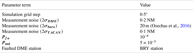
For the accuracy and integrity evaluation, simulation settings are summarised in Table 2. For the accuracy evaluation, we considered the horizontal and vertical accuracy, respectively. The horizontal accuracy bound $(\textrm{HFOM)}$ and vertical accuracy bound $({{\sigma_V}} )$
 are calculated. We can observe the accuracy of multi-DMEs in Figure 3, the RNP 1 horizontal accuracy criterion is met over 93⋅8% reference area and 35⋅0% at RNP 0⋅3 level. Though the RNP performance is only required for horizontal navigation, we still use this requirement to measure the performance of vertical navigation. 39⋅4% of area has vertical accuracy below 0⋅97 NM and 1⋅6% is below 0⋅17 NM. Comparing the different sides of the Figure 3, multi-DMEs leads to a low vertical accuracy because of their position on the ground.
Test parameter

Distribution of horizontal accuracy (left) and vertical accuracy (right) with multi-DMEs (2σbound, in meters, FL290)

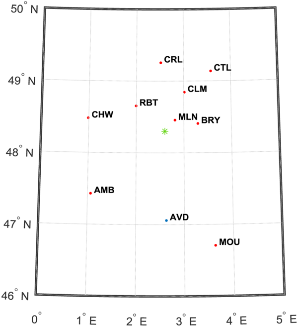
To demonstrate the performance improvement in terms of fault detection, the magnitude of fault, and the failure detection capability are analysed. We carried out a simulation using RB fault detection method for a specific example to illustrate the fault detection capability of multi-DMEs RAIM test statistics. The scenario is described in Figure 4. The red dots represent DME stations, while the blue dot is for a TACAN station. The green point is the location of the aircraft receiver.
The distribution of DME stations for the selected aircraft, receiver location: 48⋅30N, 2⋅60E (Location over France), altitude: FL290

For the illustrative example specified in Figure 4, a simulation was performed, by adding a fault in the BRY station (chosen arbitrarily), with parameters given in Table 2. The magnitude of fault is from 3500 m to 5500 m with the interval of 10 m.
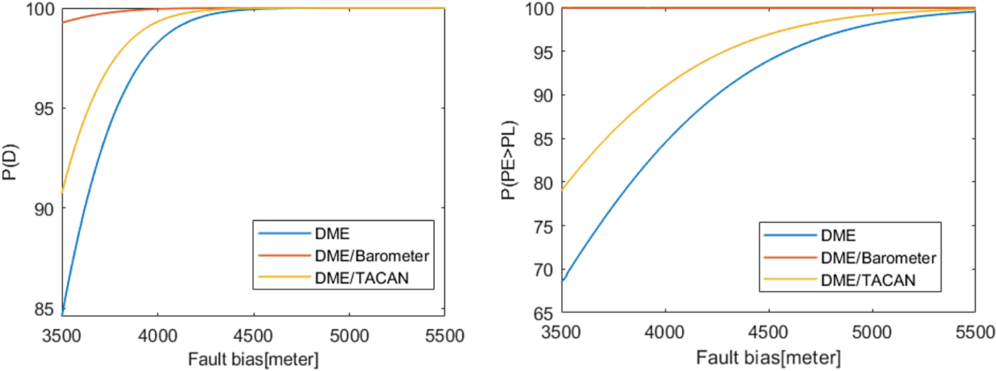
Figure 5 presents values of fault detecting rate and probability of an unacceptable position error for a range of fault magnitude. The FD rate describes the probability of the test statistics exceed the threshold, i.e. the added fault is detected. The probability of an unacceptable position error means the probability of the position error exceeds the protection level. Here, we only consider the horizontal position error and HPL. The multi-DMEs method detects 99⋅9% faults when the fault magnitude is 4460 m, while 99⋅0% faults will lead to unacceptable position errors when the fault magnitude is 5220 m.
Fault detection rate (P(D)) and probability of an unacceptable position error (P(PE > PL)) for the multi-DMEs method, barometric measurements-aided multi-DMEs, and combined multi-DMEs and TACAN

Figure 6 provides the protection level over Europe based in the scenario of Figure 2. To support navigation, the requirement of A-PNT is to achieve RNP 1 for a short/midterm and RNP 0⋅3 for long-term. The HPL thresholds are 1 NM and 0⋅3 NM, respectively. HPL is lower than 1 NM over 79⋅7% of the reference area, and lower than 0⋅3 NM over 13⋅9%.
Distribution of HPL with multi-DMEs (in meters, FL290)

Using all available DMEs can improve the performance when compared to the DME/DME. However, if we consider the RNP requirement, it is still not enough to provide the 100% coverage on Europe continent according to neither RNP 1 nor RNP 0⋅3. Other means should be applied to further improve the performance both in accuracy and integrity. Through the testing comparison between multi-DMEs, multi-DMEs aided by barometer and multi-DMEs combined with TACAN, the performance of these methods and the improvement of the proposed methods will be presented and discussed.
For the barometric measurements aided multi-DMEs method, we compared the distributions in Figures 3 and 7 that the accuracy is much better with the barometric measurements, especially in vertical accuracy. For the multi-DMEs with barometric measurements, the horizontal accuracy meets RNP 1 over 99⋅7% of the reference area and meets RNP 0⋅3 over 50⋅6%. In the right part of Figure 7, all ${\sigma _V}$ are below 30 m, which improved the vertical accuracy effectively when compared with that in Figure 3. This can be explained by the much higher vertical accuracy of barometric altitude measurements.
Distribution of horizontal accuracy (left) and vertical accuracy (right) with barometric measurements aided multi-DMEs (2σbound, in meters, FL290)

In Figure 5, when the fault magnitude is 3500 m, 99⋅3% trials trigger alarm using barometric measurements aided multi-DMEs method while 84⋅6% is detected using multi-DMEs only. The barometric measurements aided multi-DMEs method detects 99⋅9% faults when the fault magnitude is 3910 m, which is 12.3% less than the multi-DMEs method for the same failure detection rate. The probability of an unacceptable position error reaches 99⋅9% when the fault magnitude is 3500 m, which is 31⋅5% higher than the multi-DMEs method for the same fault magnitude. Thus, the barometer can help improve the FD capability. For the integrity risk evaluation, the distributions of HPL in Figures 6 and 8 are compared. The barometric measurements aided multi-DMEs method satisfies the HPL requirement for 79⋅7% of the reference area based on RNP1, while at RNP 0⋅3 level it accounts for 13⋅9%, which are same with those of multi-DMEs method. Because the measurements of barometer do not contribute to the horizontal geometry, the barometer-aided multi-DMEs method cannot help improving the horizontal positioning integrity.
Distribution of HPL with barometer aided multi-DMEs (in meters, FL290)

There are 73 TACAN stations and 23 VORTAC (VORTAC is a radio-based navigational aid for aircraft pilots consisting of a co-located VOR beacon and a TACAN system) stations in Europe. The distribution of the DME and TACAN stations in Europe is shown in Figure 9 as dots. The numbers of eligible DME and TACAN stations in the reference area with $0 {\cdot} {5^\circ }$ step at FL290 altitude are also shown in Figure 9. The station distribution in this figure looks similar with that in Figure 2, because the number of TACAN stations is small.
Distribution of DME and TACAN stations in Europe visible at FL290 altitude

For the multi-DMEs combined with the TACAN method, the horizontal accuracy can reach 96⋅0% at RNP 1 level and 60⋅6% for RNP 0⋅3 level as shown in Figure 10. Meanwhile, 54⋅8% of area has vertical accuracy below 0⋅97 NM and 1⋅6% is below 0⋅17 NM. Because TACANs are also located on the ground, there is less contribution from TACAN to the vertical accuracy. The distribution of ${\sigma _V}$ has less improvement when compared it with the multi-DMEs-only method.
Distribution of horizontal accuracy (left) and vertical accuracy (right) with combined multi-DMEs and TACAN (2σbound, in meters, FL290)

The FD rate of the multi-DMEs combined with TACAN method can also be observed in Figure 5. It detects 99⋅9% faults when the fault magnitude is 4290 m, which is 3.8% less than the multi-DMEs method for the same failure detection rate. It indicates that combining TACAN stations has good impact on the fault detection capability. For the integrity risk evaluation, the distributions of HPL in Figures 6 and 11 are compared. The multi-DMEs combined with TACAN method accounts for 86⋅7% of RNP 1 while it accounts for 37⋅7% of RNP 0⋅3. The combined TACAN method helps improve the horizontal positioning integrity more effectively.
Distribution of HPL with combined multi-DMEs and TACAN (in meters, FL290)

When comparing the multi-DMEs combined with TACAN method and the multi-DMEs-only method, we can observe that there are improvements on both accuracy and integrity with the inclusion of TACAN stations. Though there are far fewer civil TACAN stations than DME stations, some location may be covered by more than one TACAN stations, which can contribute to the geometric distribution of some areas and then benefit the integrity. Incorporating barometer altimeter measurements helps with the greater accuracy improvement, especially in vertical accuracy. Because the barometric altimeter is installed in the aircraft, at each location, a barometric measurement will be included, which can expand the number of observations, reduce the dependence on the number of DME stations, and improve the geometric performance of the DME stations both in horizontal and vertical direction. Based on the current fleet equipment, the barometric measurements aided multi-DMEs method and the multi-DMEs combined with TACAN method both can be used to support the A-PNT of multi-DMEs.
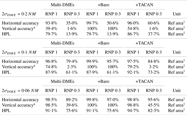
FAA flight inspection tolerance for DME range is currently 0⋅2 NM (95%) accuracy, which is discussed in the previous parts. This accuracy constraints the HDOP to be lower than 4⋅85 to reach RNP 1 accuracy requirement, which could be a limitation for the accuracy improvement. Through consultation with manufacturers, it is believed that the current DME/N ground system accuracy can be significantly better than specifications by fixing some easily correctable errors (Lo et al., Reference Lo, Chen, Enge, Peterson, Erikson and Lilley2013). Thus, it is possible for us to discuss the performance when the DME range measurement accuracy comes to 0⋅1 NM (95%) or even to 0⋅06 NM (95%). The performance of these three methods at different DME range measurement accuracy are summarised in Table 3. With the improvement of the DME range measurement accuracy, the accuracy and integrity performance are both improved. When $2{\sigma _{DME}} = 0 {\cdot} 06\; NM$ , RNP 1 can be achieved by multi-DMEs for most part of Europe landmasses. It is still a hurdle for new A-PNT technology candidates to provide RNP 0⋅3, even with the aid of other measurements, especially for integrity monitoring.
Summary of the performance for three methods at different DME range measurement accuracy

a Though the RNP performance only puts forward requirements for the horizontal accuracy, for the convenience of comparison, we apply these RNP horizontal accuracy requirements to the vertical accuracy.
8. A case study: airport performance evaluation
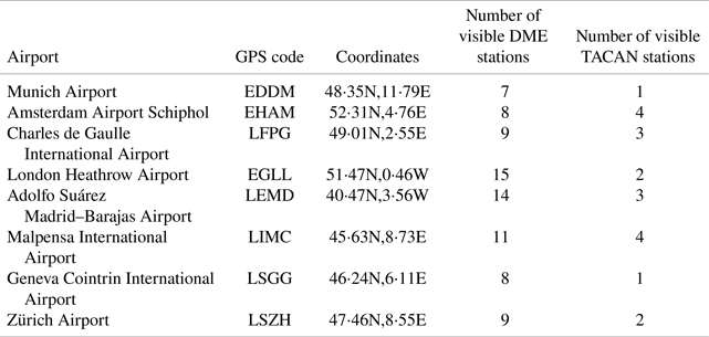
This study evaluates airport performance based on multi-DMEs methods considering eight major airports in Europe. The airport information is listed in Table 4. From Table 4, using Eurocontrol DME/TACAN database, Munich Airport, as the airport with fewest visible DME stations is selected as a specific airport to be studied. The airport with few visible DME stations would lead to the worst case multi-DMEs performance among these big airports. The distribution of the DME stations around Munich Airport (48…49⋅5°N, 11 … 13°E, namely the reference area later in the document) is shown in Figure 12 as red dots. The green star in Figure 12 represents the center coordinates of Munich Airport (48⋅35N, 11⋅79E). The only visible TACAN station at Munich Airport center coordinates is on 44⋅03N, 11⋅00E with 200 NM coverage, which has not been shown in this figure. The numbers of eligible DME stations in the reference area with $0 {\cdot} {05^\circ }$ grid step at 5000 m altitude are also shown in Figure 12.
Major airports information

Distribution of DME stations around Munich Airport (marked as green star) visible at 5000 m altitude

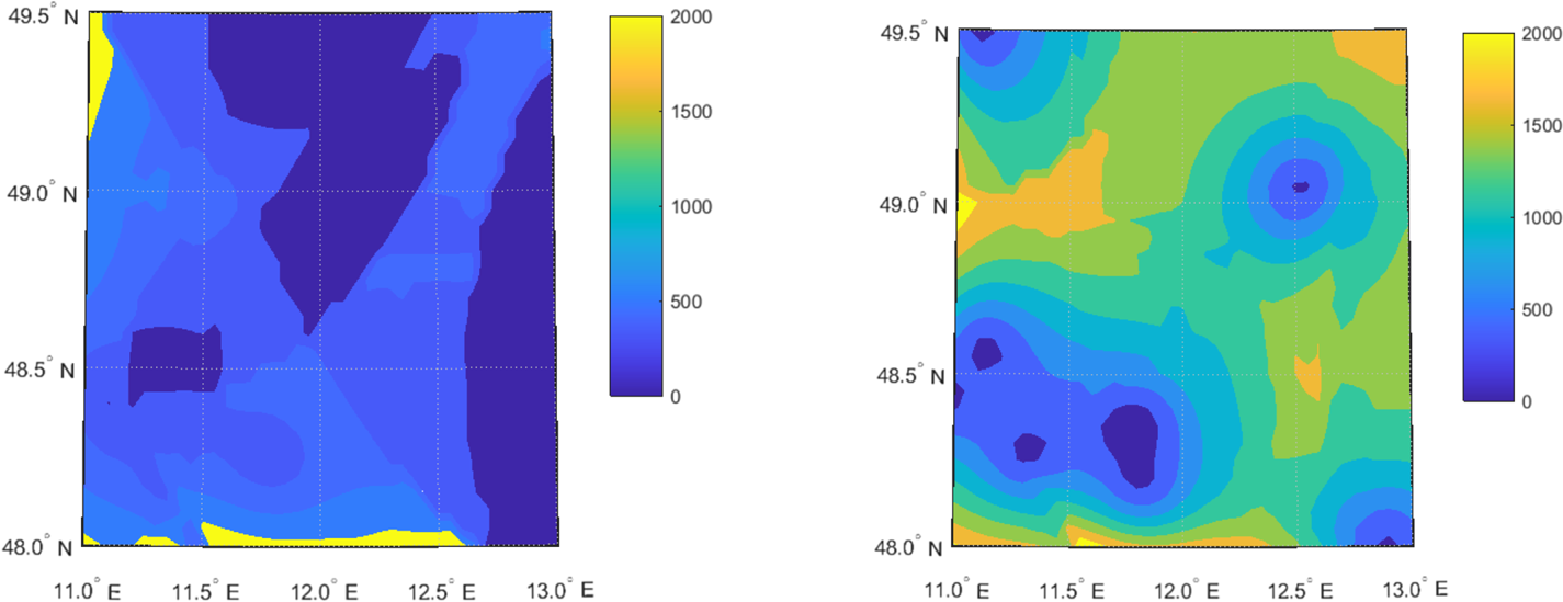
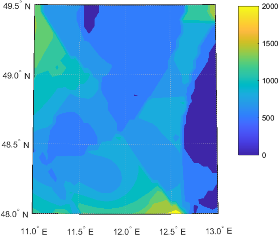
The accuracy of multi-DMEs can be observed in Figure 13. The RNP 1 horizontal accuracy criterion can be met over 100% reference area and 43⋅0% at RNP 0⋅3 level. Meanwhile, 99⋅9% of the vertical accuracy is below 0⋅97 NM (equivalent RNP 1 accuracy requirement if expressed for the vertical). 0⋅3% of the vertical accuracy is below 0⋅17 NM (equivalent RNP 0⋅3 accuracy requirement if expressed for the vertical), which makes the vertical accuracy is worse than the horizontal accuracy. Figure 14 provides the protection level around Munich Airport based in the scenario of Figure 12. The proportion of HPL that meets RNP 1 requirement reaches to 100% of the reference area. The proportion of HPL that meets RNP 0⋅3 requirement is only 2⋅3% of the reference area.
Distribution of horizontal accuracy (left) and vertical accuracy (right) with multi-DMEs for Munich Airport (2σbound, in meters, alti: 5000 m)

Distribution of HPL with multi-DMEs for Munich Airport (in meters, alti: 5000 m)

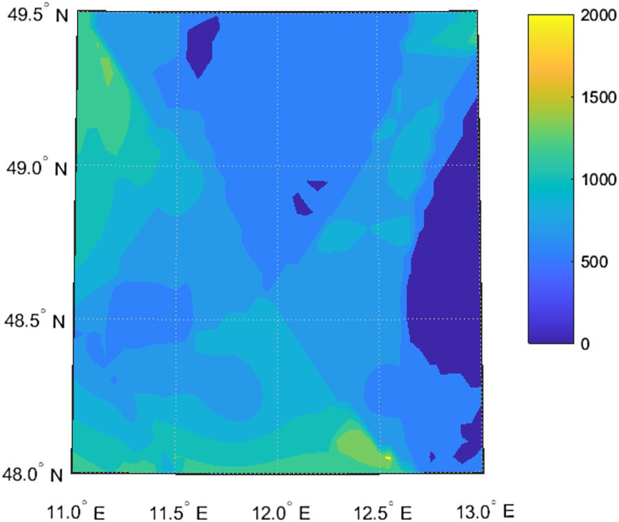
For the barometric measurements-aided multi-DMEs method, both accuracy and integrity performance around the Munich Airport can meet the RNP 1 requirement in Figure 15. The horizontal accuracy of 57⋅2% reference area meets the RNP 0⋅3 requirement while the vertical accuracy of 100% reference area is below 0⋅17 NM. The proportion of HPL that meets RNP 0⋅3 requirement is 2⋅3% of the reference area in Figure 16. With the aid of a barometer altimeter, the accuracy performance around Munich Airport can be improved, especially the vertical accuracy.
Distribution of horizontal accuracy (left) and vertical accuracy (right) with barometer aided multi-DMEs for Munich Airport (2σbound, in meters, alti: 5000 m)

Distribution of HPL with barometer aided multi-DMEs for Munich Airport

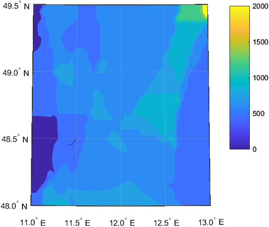
Since there are more TACAN stations around airports, from Figure 17 and Figure 18 we can see that large performance improvements are achieved with the multi-DMEs combined with TACAN method, which is because of the increased horizontal distributions of TACAN stations and the higher measurement accuracy. There are larger changes in the proportions of both horizontal accuracy and integrity performance that meets RNP 1 with the combination of TACAN stations. The combination of TACAN helps the improvement of horizontal geometry. The proportion improvement of HPL meeting RNP 0⋅3 is increased by 16⋅3%.
Distribution of horizontal accuracy (left) and vertical accuracy (right) with combined multi-DMEs and TACAN for Munich Airport

Distribution of HPL with combined multi-DMEs and TACAN for Munich Airport

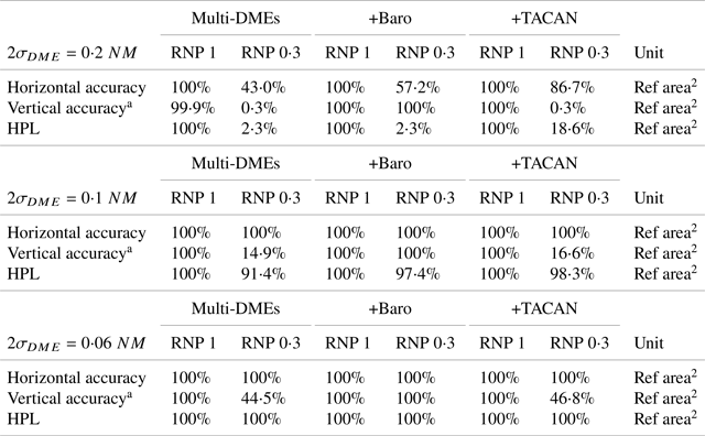
The navigation performance of these three methods with the DME range measurement 2σ accuracy varying among 0⋅2NM, 0⋅1 NM and 0⋅06 NM is presented in Table 5. The performance at different DME range measurement accuracy is also summarised in Table 5. When $2{\sigma _{DME}} = 0 {\cdot} 1\,\textrm{NM}$ , RNP 1 can be achieved by multi-DMEs over the Munich Airport region. When $2{\sigma _{DME}} = 0 {\cdot} 06\; \textrm{NM}$
 , RNP 0⋅3 can be achieved by multi-DMEs. When we focus on a specific airport, especially big airports, the navigation performance at 5000 m altitude over the airport region is better than over the European landmass. This is because of the sufficient number of visible DME stations and reasonable distribution of DME stations. Thus, it is possible for multi-DMEs to provide high-performance A-PNT services around airports.
Summary of the performance for Munich airport

a Though the RNP performance only puts forward requirements for the horizontal accuracy, for the convenience of comparison, we apply these RNP horizontal accuracy requirements to the vertical accuracy.
9. Conclusion
The multi-DMEs would be used as a reversionary capability in case of GNSS outage. In this work, we first evaluate accuracy and integrity performance of multi-DMEs assuming all-in-view DME positioning is achieved. With multi-DMEs, though it has improved the performance compared to DME/DME, we cannot achieve RNP 1 service in whole Europe landmasses, let alone RNP 0⋅3. Then, based on the existing installations, the barometric measurements-aided multi-DMEs method and the multi-DMEs combined with TACAN method are both used to complement multi-DME supporting A-PNT. With the inclusion of TACAN stations, the horizontal accuracy and integrity are increased, which helps approach the RNP 1 requirement. The barometric measurements-aided multi-DMEs method can help improve the accuracy, especially the vertical accuracy. If the balance between computation increases and performance improvement is considered, the TACAN-combined method should be the first choice because of the better integrity performance. Finally, the performance of different DME range measurement accuracy is compared. The DME range measurement accuracy of 0⋅2 NM (95%) could not support RNP 1 requirement. The performance is improved with the increased DME range measurement accuracy. When the DME range measurement accuracy requirement becomes more stringent to 0⋅06 NM (95%), RNP 1 can be achieved by multi-DMEs for most part of Europe landmasses. Thus, improving the DME ranging accuracy for the future study could be interesting but may not fulfil the RNP 0⋅3 target per se. It is still a hurdle for new A-PNT technology candidates to provide RNP 0⋅3, even with the aid of additional measurements. The long-term solution considering a full fleet to equip could provide a reversionary solution in case of GNSS outages based on eDME, because carrier phase measurements provide a higher accuracy than slant range measurements. However, based on our case study, if we only consider the navigation performance around airports, the RNP 0⋅3 could be achieved when the DME measurement accuracy becomes 0⋅06 NM (95%). Also, as the number of DME channels on-board the aircraft is limited, it is crucial to determine the impact of the DME station-selection method on this navigation performance. Accuracy degrades when decreasing the number of DME stations accessed, but integrity-bounding performance may have an optimum number of DME stations and geometry that remains to be estimated. Station selection and associated performance is the topic of additional papers proposed by the authors.