I. INTRODUCTION
There are numerous research activities on using radar systems for contour scanning as an alternative to laser scanners in industrial and process automation applications with harsh environments. For instance, radar scanners are already used for supervision and control of huge mining machines [Reference Winkel, Hahn, Augustin and Nienhaus1, Reference Widzyk-Capehart, Brooker, Scheding, Hennessy, Maclean and Lobsey2]. Systems presently in use are working at millimeter-wave frequencies. For angular scanning, they are using mechanical movements. In comparison to laser scanners, however, size and weight of the moving elements are much higher at millimetre wave frequencies. This makes the structures more sensitive to vibrations and impacts always present in the aforementioned environments, and finally result in higher maintenance efforts. The requirements for high angular resolution and wide field of view lead either to huge antenna structures and gimbal systems [Reference Widzyk-Capehart, Brooker, Scheding, Hennessy, Maclean and Lobsey2] or to groups of sensors [Reference Winkel, Hahn, Augustin and Nienhaus1]. With respect to these problems electronically steerable arrays suggest themselves as an alternative. For realization in their classical form as active phased arrays, however, radio frequency (RF)-complexity would be very high and reasonable key components are not commercially available. This leads to the digital beam-forming (DBF) approach, in which complexity is partly shifted from hardware to software. As the requirements for reaction times in supervision and control of huge mining machines or in process automation are moderate in comparison to aerospace and defense applications, DBF systems can work in time-multiplex allowing even simpler hardware. In [Reference Winkel, Nienhaus, Mayer, Gronau and Menzel3], an experimental radar sensor working at a frequency of 24 GHz and originally designed for automotive radar was successfully evaluated for visualizing escarpments in an open coal pit. Encouraged by these results, research work was started to transfer the concept to the E-band with a frequency range of 76–81 GHz. The hardware extension presented here is part of the result of this work.
II. CONCEPT
Starting from the availability of a bi-static FMCW-radar sensor with one transmit and two receive channels, the DBF system is based on the idea of replacing the passive antenna structure with a switched antenna array. This provides a modular concept making maximum use of the available components. By maintaining sampling theorem in spatial domain for imaging a half-plane, all the antenna elements are arranged linearly. Each antenna element has a wide radiation diagram in the imaging plane which covers the complete field of view of the sensor. For optimum noise, figure 32 switched transmit elements are chosen and the two receive channels of the available sensor are directly connected to two receive elements. To take the advantage of synthetic array extension [Reference Mayer, Buntz, Leier and Menzel4], the two receive elements are placed left and right to the transmit antenna row.
In this setup, the transmit channel of the FMCW-sensor is successively switched to each of the 32 transmit elements and one FMCW-ramp per switch state is performed. After one measurement cycle, data from 64 FMCW-scans are available for signal processing. For subsequent DBF of the recorded data, coherency of the successively performed scans is necessary. This condition is fulfilled by the used FMCW-sensor, which contains a synthesizer architecture for frequency ramp generation.
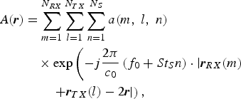
If, in a basic operation mode, FMCW radar scans with identical ramped waveforms are executed for all receive–transmit combinations, a two-dimensional (2D) radar image A(r) for position vectors r = (R|θ) can be obtained by phase correction and coherent integration of the real valued sampled and stored data a(m, l, n) according to equation (1)
 $$\eqalign{A\lpar {\bi r}\rpar & = \sum_{m = 1}^{N_{RX}} \sum_{l = 1}^{N_{TX}} \sum_{n = 1}^{N_S} a\lpar m\comma \; l \comma \; n\rpar \cr & \quad \times \exp\left(-j \displaystyle{{2\pi} \over {c_0}}\left(f_0 + St_{S}n\right)\cdot \left\vert {\bi r}_{RX} \lpar m\rpar \right. \right. \cr & \quad \quad \left.\left. + {\bi r}_{TX} \lpar l\rpar - 2{\bi r} \right\vert \right)\comma \; }$$
with
- a(m, l, n)
= recorded samples
- N TX
= number of transmit elements
- N RX
= number of receive elements
- N s
= number of samples per waveform
- t s
= sampling time
- S
= frequency slope of ramped waveform
- f 0
= start frequency
- c 0
= speed of light
- rTX(l), rRX(m)
= position vector of lth transmit and mth receive element
- ϕTX(l), ϕRX(m)
= phase correction value of lth transmit and mth receive element.
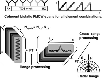
With a uniform linear array, constant rate sampling and linear frequency ramps, the phase correction of (1) can be performed with a two step Fourier-transform. This is illustrated in Fig. 1 for a simplified example with four transmit elements. The complex valued range spectra for all bistatic radar scans are calculated by Fourier-transforms over the time domain samples N S in a first processing step. In the second processing step, Fourier-transforms are performed for each range position over the range spectra values of the available element combinations N synth = N RX · N TX of the synthetic array. Combining indices m and l to an index l′ for element combinations, the two cascaded transforms can be expressed in (2). To emphasize the Fourier-transform structure substitutions 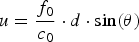 $u = \displaystyle{f_{0} \over c_{0}} \cdot d \cdot \sin\lpar \theta\rpar $ for the angular coordinate and v = S/c 0t s · R for the range coordinate are used in (2). The hardware related phase differences of the l′ transmit-receive-combinations of the synthetic array can be corrected by a phase shifting term exp−jϕ(l′) in between the two steps.
 $$A\lpar v\comma \; u\rpar = \sum_{l^{\prime} = -n_{\rm tx} }^{+n_{\rm tx}} \left(\sum_{i = 1}^{n_{s}} a_{s} \cdot \exp^{-j2\pi vi}\right)\cdot \exp^{-j\phi\lpar l^{\prime}\rpar } \cdot \exp^{-j2\pi ul^{\prime}}.$$
Radar image processing with a two step Fourier-transform.

As a result, signal intensity distribution over a polar grid covering one half-plane is obtained. Owing to the sine function in the substitution of u, angular cell distribution of the polar grid is not uniform, and angular cells size increases with declination from boresight direction.
The two step Fourier-transform is the simplest DBF method, applicable to the hardware setup. Using fast Fourier transforms for the Fourier-transforms it can be implemented very efficiently in a state of the art digital signal processor. More advanced beam-forming methods, however, can be used to increase resolution and quality of the radar image [Reference Mayer, Gronau, Menzel and Leier5–Reference Feil and Chaloun7].
III. HARDWARE SETUP
A) DBF extension hardware
1) SWITCHED ARRAY ANTENNA
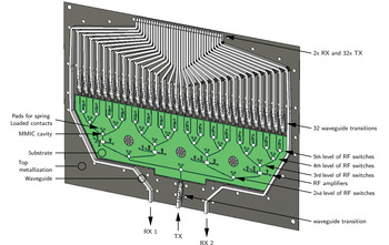
The concept behind the DBF extension is a switched array antenna with 32 transmit (TX) elements and two receive (RX) elements positioned on either side of the array (see Fig. 3). To switch the TX channel of the FMCW sensor to one of the 32 TX elements requires five levels of single pole double throw switches. The switches of one level are either all switched to the left or to the right. Four amplifiers are inserted between the second and third levels of switches to achieve a good compromise between usable gain and required RF printed circuit board (PCB) space. The usable gain is restricted by the saturated output power, lower the input power to the amplifiers more gain can be used. Placing the amplifiers between the second and third levels of switches attenuates the TX power of the FMCW sensor by the insertion losses of the first and second level switches and the line losses.
The switch “network” was realized using a microstrip line technique in conjunction with a metal-backed substrate (see center of Fig. 3) [8]. To mount the switches and amplifiers cavities were formed by removing the substrate through milling. Another technique for forming cavities is laser ablation. The DC pads are contacted by spring loaded contacts to transmit the switching voltages for the switches and the supply voltages for the amplifiers from the DC PCB to the RF PCB (see lower part of Fig. 2) [9]. The aluminum lid placed on top of the metal-backed substrate contains milled structures which form the primary radiators (TX and RX elements) of the DBF radar and the waveguide transitions to connect the microstrip line switch network. These two developed structures are presented in the next two sections.
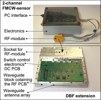
Photograph of the FMCW-sensor consisting of an RF-module and an electronics PCB (in the plastic box) and the DBF-extension with the primary radiators in front. Interconnection and power supply cables are removed to improve clarity.

Depiction of the switched array antenna with 32 transmit (TX) elements and two receive (RX) elements positioned on either side of the array. The components shown are top metallization and the substrate of the used metal-backed substrate, as well as the rectangular waveguides milled into the aluminum lid which is placed on top of the metal-backed substrate (inverse representation). Not shown here is the metal plate on the other side of the substrate.

2) WAVEGUIDE RADIATOR WITH TWO STEPS
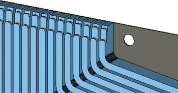
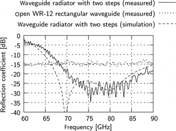
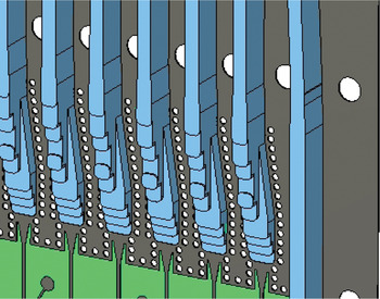
The concept of two steps was chosen to develop a primary radiator for the DBF radar (see Fig. 4). The lengths and heights of the steps were optimized to minimize the reflection coefficient in the frequency range from 76 to 81 GHz [10]. The absolute value of the reflection coefficient was measured with a scalar WR-12 measurement setup (see Fig. 5). The reflection coefficient is below the reflection coefficient of an open WR-12 (E band) rectangular waveguide in the frequency range of interest from 76 to 81 GHz as expected from the simulation results which are also shown in Fig. 5. The spacing between the radiators forming the switched array antenna is 1.81 mm which is 0.46 λ at 76 GHz and 0.49 λ at 81 GHz fulfilling the spatial Nyquist criterion for the whole frequency range.
Enlarged depiction with focus on the waveguide radiators with two steps which function as primary radiators for the DBF radar.

Measured and simulated reflection coefficient of the developed waveguide radiator with two steps in comparison with the measured reflection coefficient of an open WR-12 (E band) rectangular waveguide.

3) WAVEGUIDE TRANSITION FROM WR-12 RECTANGULAR WAVEGUIDE TO MICROSTRIP LINE
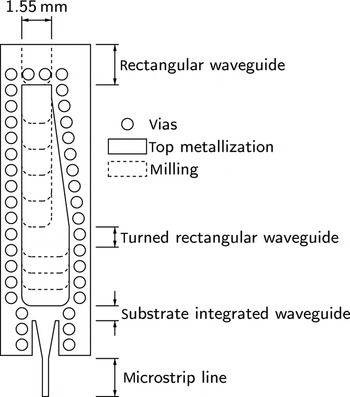
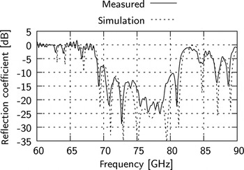
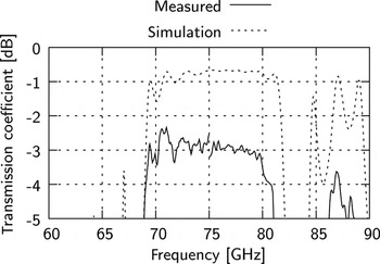
The developed transition from WR-12 rectangular waveguide to microstrip line consists of three “internal” transitions to a turned rectangular waveguide [Reference Schulwitz and Mortazawi11] and a substrate integrated waveguide (see Figs 6 and 7) [12; Reference Feil and Bauer13]. The internal transitions were first optimized individually and then the whole transition from rectangular waveguide to microstrip line was optimized to maximize the transmission coefficient in the frequency range from 76 to 81 GHz [10]. Two transitions arranged back to back (connected by a microstrip line) were characterized with the scalar WR-12 measurement setup (see Figs 8 and 9). The measured reflection coefficient was below −10 dB in the frequency range from 76 to 81 GHz, the measured transmission coefficient above −4 dB.
Enlarged depiction with focus on waveguide transitions.

Layout of the developed transition from WR-12 rectangular waveguide to microstrip line.

Measured and simulated reflection coefficient of two transitions from WR-12 rectangular waveguide to microstrip line arranged back to back.

Measured and simulated transmission coefficient of two transitions from WR-12 rectangular waveguide to microstrip line arranged back to back.

B) Experimental results
1) DEMONSTRATION SYSTEM
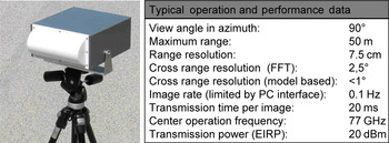
The hardware extension described in the previous sections has been combined with the two channel FMCW-sensor in a special sensor housing to a compact imaging radar demonstration system illustrated in Fig. 10. A cylindrical dielectric lens fabricated from polytetrafluoroethylene in the front-side of the sensor housing is focusing the beam of the sensor in elevation, perpendicular to the imaging plane. By the lens antenna, sensor extension and sensor are optimally protected in harsh environments. The view angle of the sensor, however, is limited to 90°. Hence, the lens is a compromise with respect to robustness of the over-all assembly. Planar antenna alternatives could provide higher view angles, but have very sensitive surfaces. The imaging processing cannot be done in the electronics of the FMCW-sensor because of limited signal processing power. Hence, preprocessed raw data are transferred via a standard interface to a host PC, which is generating, evaluating and visualizing the radar images.
Photograph and technical data of the imaging radar demonstration system.

2) MEASUREMENT RESULTS
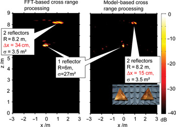
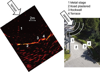
In this section radar images from two sceneries are presented to demonstrate the systems functionality. The first scenery was taken in an absorbing chamber. Three corner-reflectors were placed at different ranges and angles inside the chamber. In Fig. 11, two measured radar images are depicted as logarithmic pseudo-color-coded intensity plots with a dynamic range of 40 dB. In the radar image in the left, the angular resolution limit of the sensor with conventional beam-forming is demonstrated. Two small reflectors, placed at a range of 8.2 m with a cross range distance of Δx = 0.34 m appear as two clearly separable maxima in the radar image. In the radar image on the right, a super-resolution technique based on linear prediction is used for cross range processing [Reference Mayer, Gronau, Menzel and Leier5]. Using this technique the two reflectors at 8.2 m can still be resolved if the cross range distance is reduced to Δx = 0.15 m. This demonstrates an angular resolution of about 1°. In both images, there are, however, some clutter targets at levels of approximately −25 dB. Some of them can be explained by parasitic radiation of the receive channels, others could be residual reflections of the walls of the absorbing chamber. Figure 12 depicts a result of first experimental tests on terrain imaging. For this radar image, the imaging plane of the sensor was arranged perpendicular to the terrain. With the help of a photograph of the scenery one can clearly allocate the observed terrain cut by a chain of strong maxima in the intensity plot. All the plastered road, the rockwalls and the terraces grown over with grass reflect sufficient energy for identification and locating. Reflections of the metal stage are quite low, as they are located at the view angle limit of the sensor. Clutter and noise maxima behind the reflection chain of the terrain contour are having a strong variance. In a static scenery they can be reduced by averaging. The image in Fig. 12 is without additional averaging, so integration time equals the transmission time of 20. Cross-range resolution of the radar image has been improved by autoregressive array extension to three times the physical aperture.
Measurement results for three ideal reflector targets in an absorbing chamber.

Outdoor measurement to demonstrate terrain imaging. Left: radar image with a dynamic range of 40 dB. Right: photograph of the scenery.

IV. CONCLUSION
Concept, design, realization and test results of a hardware extension for a two channel FMCW-radar sensor for an operation frequency of 77 GHz have been presented. The hardware extension contains a transmit multiplexer from one transmit channel to 32 transmit antenna elements and two non-switched receive antenna elements. The combination of FMCW-sensor and the extension can be used to generate 2D radar images from successively recorded 1D FMCW-radar measurements. Generation of the radar images is done by software, and methods of DBF can be used. For static or slowly moving target-sceneries, the concept allows high range- and angular resolution despite its simple and affordable hardware architecture. Future applications could be found in the fields of process and industrial automation, where extreme environmental conditions do not allow the use of optical sensors or laser scanners.
 Markus Goppelt received his Dipl.-Ing. degree in electrical engineering from the University of Ulm, Germany, in 2008. From 2008 to 2012 he worked as a research assistant in the Institute of Microwave Techniques of the University of Ulm in cooperation with the Daimler AG in the publicly funded Radar on Chip for Cars project. Since 2012, he is with the Continental AG in Ottobrunn as a system architect for 77/79 GHz radar sensors.
 Peter Feil received his Dipl.-Ing. degree in 2005 from the University of Ulm, Germany. From 2005 to 2011 he worked as a research assistant at the University of Ulm, Institute of Microwave Techniques. His research topics were broadband millimeter wave imaging radars and their applications in industrial and security areas. Currently, he is with the EADS Deutschland GmbH.
 Winfried Mayer received the Dipl.-Ing.(BA) degree in communication technology from Berufsakademie Ravensburg in 1994. From 1994 to 2001 he was with EADS Deutschland Microwave Factory / R&D. From 2002 to 2007 he was doing research on imaging radar sensors and digital beam-forming at the Institute of microwave techniques of Ulm university. In 2008, he received the Dr.-Ing. degree from Ulm University. Since 2007, he is with Endress + Hauser GmbH + Co. KG, Maulburg, responsible for predevelopment in radar technology. He has design and system experience in the fields of microwave synthesizers, millimeter-wave modules, front ends for sensor applications and system aspects of automotive and industrial radar sensors. His present research interests are low-cost and low-power technologies for millimetre-wave sensor front-ends as well as system innovations for future radar level sensors.