Introduction
Ultra-Wide Band (UWB) is a widely used technology in communication systems as it provides a high data rate and reliable communication. UWB technology has been attracting much attention and rapidly advancing and leading to innovations [Reference Dharmarajan, Kumar and Afullo1]. However, it is utilized only in a specific application that requires a short distance for communicating due to its low power and its multipath problem [Reference Singh and Verma2]. The antenna is the critical component in the UWB technology design because it needs several demands such as small size, low cost, simplicity, wide operating band, and special radiation patterns features [Reference Reddy, Kamma, Mishra and Mukherjee3–Reference Ibrahim and Ali7]. Many antenna types had been utilized such as planar radiators [Reference Suriya and Anbazhagan8, Reference Aboelleil, Ibrahim and Khalaf9], slotted annular ring monopole antenna [Reference Sipal, Abegaonkar and Koul10], and slot antenna [Reference Saad and Mohamed11, Reference Saad12] as a single element to be integrated into the multiple input multiple output (MIMO) systems. The single-element design should take into consideration the challenges raised by the integration process. One of the most popular antennas to be used in the MIMO system is the slot antenna. It is the most attractive antenna due to its favorable impedance characteristics, simple implementation, and ease of integration with active devices [Reference Saad and Mohamed11].
MIMO technology is merged with UWB technology to reduce the multipath problem and increase the system's data rates. A lot of work is done in the UWB-MIMO field and is faced with many challenges in their designs for instance suppressing the coupling between the MIMO elements and increasing the number of elements of the design [Reference Singh and Verma2].
In MIMO systems, mutual coupling between two antennas has a negative effect on the efficiency of designs [Reference Gangwar, Sharma, Kanaujia, Singh and Lay-Ekuakille13,Reference Biswas, Pattanayak and Chakraborty14]. As multiple antennas are placed close to each other to design a compact device, so, mutual coupling between them should be minimized to attain high isolation between them. It also affects the individual antenna performance efficiency [Reference Khan, Capobianco, Naqvi, Ijaz, Asif and Braaten15]. Many suppressing mutual coupling techniques are presented as decoupling structures [Reference Zhang, Lau, Sunesson and He16] such as tree-like structures [Reference Zhang, Ying, Xiong and He17], parasitic meander lines [Reference Ghosh, Ghosal, Mitra and Chaudhuri18], and inserting stubs [Reference Iqbal, Saraereh, Ahmad and Bashir19–Reference Ali, Ibrahim and Mohamed21]. Also, a variety of stub and slot structures were inserted between the antenna elements to reduce the mutual coupling for better MIMO performance. These structures have been added to increase the current path, and suppress the mutual coupling. Also, as reported in references [Reference Ibrahim and Ali7–Reference Aboelleil, Ibrahim and Khalaf9, Reference Khan, Capobianco, Naqvi, Ijaz, Asif and Braaten15, Reference Koziel, Bekasiewicz and Cheng22,Reference Srivastava, Kumar, Kanaujia, Dwari and Kumar23] the elements were perpendicularly fed and high isolation was achieved using polarization diversity.
Another mutual coupling technique presented in [Reference Zhang, Zhang and Tian24] utilizes a metal reflector at the back of the antenna elements. Moreover, the neutralization line is also an efficient suppressing technique between the close elements. These decoupling structures are useful; however, few of them can achieve high isolation of more than 20 dB over the UWB band, especially when the elements share a connected ground [Reference Wang, Wang, Tan, Wu, Gao and Liu25].
This paper presents a compact UWB-MIMO antenna using a connected ground slot antenna with an L-stub feedline, in addition to 4-port compact MIMO system measurement methodologies and challenges. The single element of slot antenna design investigated the effect of stub feed and connected ground effect on the antenna performance. A design of 4-port MIMO antenna is presented, analyzed, and measured. The CST microwave studio software is utilized to extract the simulation outcomes. The organization of the paper is as follows: ‘UWB single-element slot antenna design evolution’ is the design evolution of the single UWB slot antenna. The four-port MIMO antenna is investigated in ‘MIMO slot antenna with connected ground design’. ‘MIMO Analysis’ discussed the MIMO analysis and performance. Finally, ‘Conclusion’ is the conclusion.
UWB single-element slot antenna design evolution
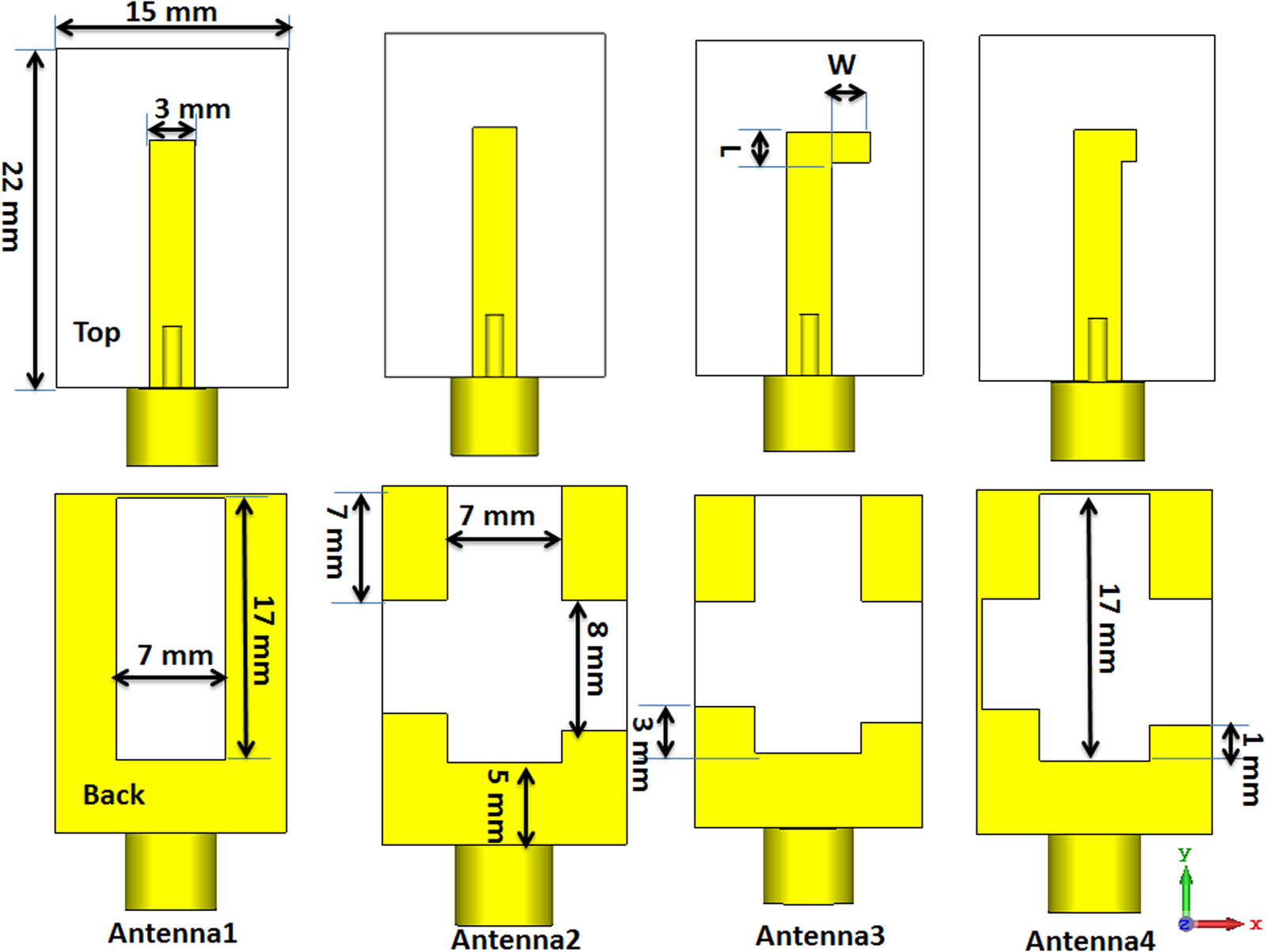
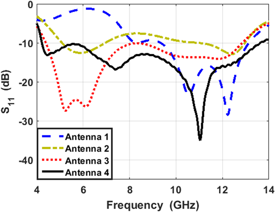
This section introduces the antenna single element 4 versions and their design details. The suggested antenna evolution is presented in Fig. 1. The first antenna design (see “Antenna 1” in Fig. 1) is given by a slot antenna with a rectangular slot in the ground plane and a 50 Ω microstrip line printed on the other side of the FR4 substrate with 4.4, 0.003, and 1.6 mm dielectric constant, tan δ, and thickness, respectively. The antenna is worked with S 11 ≤ −10 dB from 8–13 GHz as illustrated in Fig. 2 (dashed blue line). To improve the antenna bandwidth, the second antenna design is created as shown in Fig. 1. The slot shape is changed from rectangular to cross-shaped. The antenna matching is improved especially at the lower frequency band from 5.5–6.5 GHz as displayed in Fig. 2 (dotted dashed green line). The feeding line length of the proposed antenna can affect the antenna matching so any change in it the antenna matching can be changed and improved. So, the third antenna configuration is developed as shown in Fig. 1. The slot length and width are the same with antenna 2 while an open stub resonator (L-shaped) is added at the end of the microstrip line to improve the antenna matching as shown in Fig. 2. The antenna 3 has bandwidth with S 11 ≤ −10 dB from 4.3–12.5 GHz as illustrated in Fig. 2 (dotted red line).
The suggested UWB single-slot antenna evolution.

The S 11 simulated results of the four versions of the slot antenna.

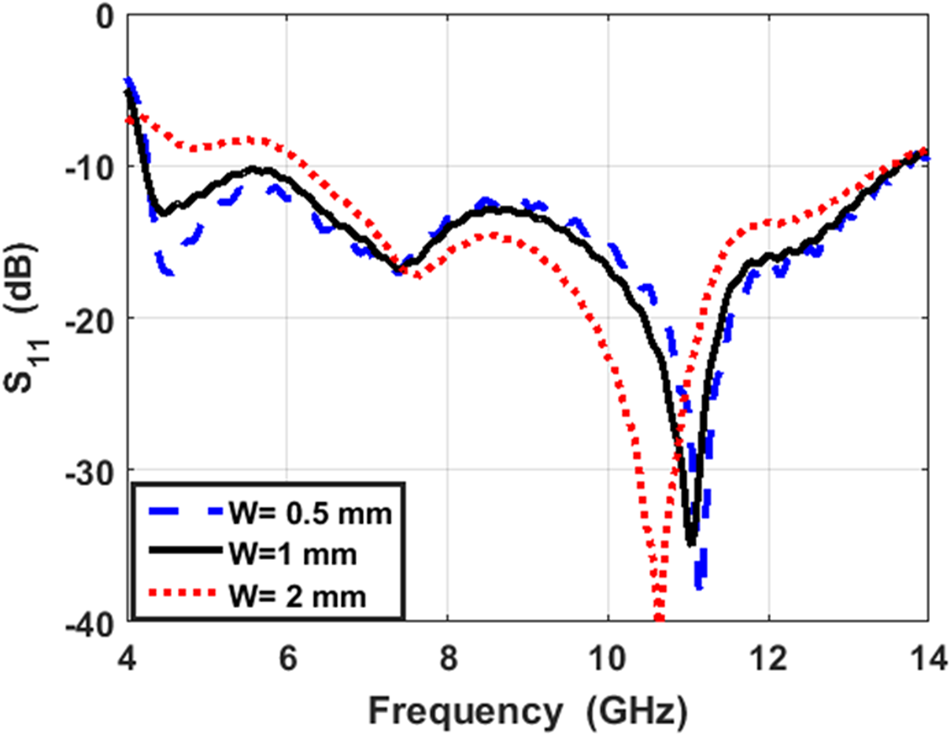
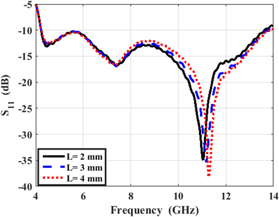
Finally, to connect the antennas with the same ground as we will discuss in the next section to compose the proposed MIMO, a small stripline is connected as shown in Fig. 1, and the stub length and width are optimized to achieve the desired frequency band as shown in Fig. 2 because the antenna response is changed by adding the small strip. The suggested structure (antenna 4) has bandwidth with S 11 ≤ −10 dB from 4–14 GHz as illustrated in Fig. 2 (black solid line) which can be utilized in the UWB system. The effect of the open stub L-shaped resonator length (W) and width (L) on the suggested antenna matching (antenna 4) is displayed in Figs 3 and 4 respectively. It is seen that the antenna matching can be affected by increasing the stub length (W) from 0.5 to 2 mm especially at the lower frequency band as shown in Fig. 3. While the stub width (L) doesn't have a critical effect on the antenna response as shown in Fig. 4.
The S 11 simulated results of the suggested slot antenna with varying stub length (W).

The S 11 simulated results of the suggested slot antenna with varying stub width (L).

MIMO slot antenna with connected ground design
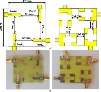
Figure 5(a) displays the front and back layout of the suggested 4 ports slot antenna. The single unit discussed in the previous section is arranged perpendicularly to each other as shown in Fig. 8. The antenna at port 1 has a 90o orientation with antennas at port 2 and port 4 while has a 180o orientation with the antenna at port 3. A small strip is used to connect all antennas to achieve the connected ground configuration. The separation between the feed lines is 22 mm (0.29 λ 0 at 4 GHz). While the separation between the slots in the ground plane is 9.4 mm (0.12 λ 0 at 4 GHz). The suggested MIMO antenna has an overall size of 47 mm × 47 mm. Due to the symmetry property of the suggested antenna, the results that appeared at port 1 are only extracted and discussed. Figure 5(b) shows the fabricated front and back photos of the suggested MIMO antenna prototype with an SMA connector. The suggested antenna is fabricated using a chemical etching process (photo-lithographic technique).
4 ports UWB slot antenna configuration (a) front and back 2 D layout with dimensions (b) The front and back photo of the fabricated prototype.

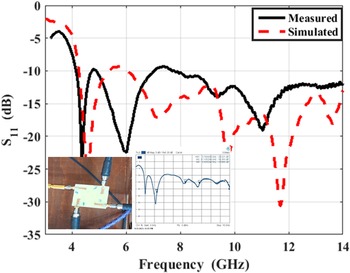
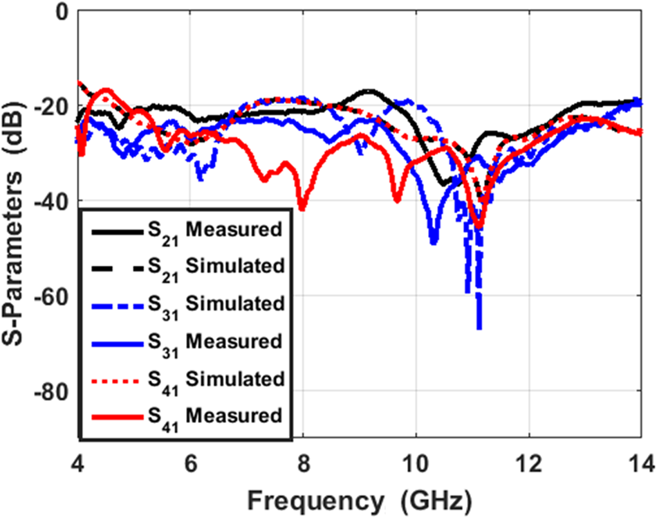
The VNA (R&S ZVB 20) with 4 ports is utilized to measure the antenna S-parameters as shown in Figures 6 and 7. The tested and simulated S 11 of the suggested MIMO slot antenna at port 1 is illustrated in Fig. 6. Also, Fig. 6 displays the suggested antenna connected with VNA cables and the S 11 screenshot from the VNA screen. The antenna shows tested and simulated results with S 11 ≤ −10 extended from 4–14 GHz with good consistency between results. The S 21, S 31, and S 41 simulated and tested results (at port 1) of the suggested antenna are shown in Fig. 7. The tested results have isolation of more than 23 between the antenna in orthogonal orientation (antennas at port1, 2, and the port at 1, 4). The isolation is reduced to 20 dB between antennas at port1, and 3. As well, a good trend is achieved between the two results with a small shift because of the fabrication, soldering process, and human errors which can't be avoided.
Simulated and measured reflection coefficient of the proposed antenna at port 1.

Simulated and measured mutual coupling coefficient results of the proposed antenna at port 1.

From the previous results, we can say that, achieving high isolation of more than 20 dB over the UWB band, especially when the elements share a connected ground and compact size are big challenges that confirm the novelty of our work in MIMO antenna design.
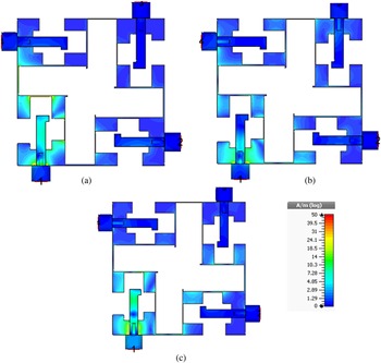
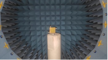
Figure 8 illustrates the current distribution results of the suggested 4 ports slot antenna at port 1 at 4.5, 6.5 and 8.5 GHz. The concentration of the current is around the slotted ground of antenna 1 and a small amount of current is passed in the nearby antennas at the displayed three frequency bands which validate the low coupling between elements. The radiation patterns measuring the setup of the suggested antenna at port 1 are illustrated in Fig. 9
The suggested 4 ports UWB slot antenna current distribution at port 1 (a) at 4.5 GHz (b) at 6.5 GHz (c) at 8.5 GHz.

The setup inside the anechoic chamber of the suggested antenna for radiation patterns measurements.

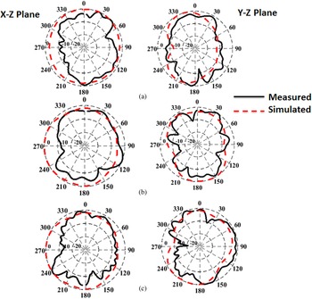
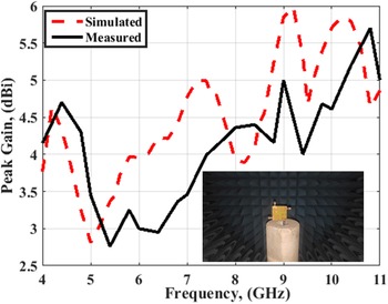
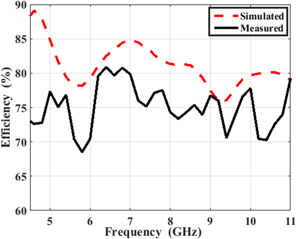
The normalized radiation patterns in the x–z and y–z planes of the suggested 4 ports slot antenna at port #1 and the other ports attached with matched loads at 4.5, at 6.5 and at 9.5 GHz are shown in Fig. 10. The semi-omnidirectional patterns are achieved in the x–z plane and the semi-directional patterns are achieved in the y–z plane. But, it can be seen that at higher frequency bands the semi-omnidirectional patterns can be observed at the two planes. Also, the same trends between the two results (simulated and tested) can be observed. The peak gain of the suggested antenna at port 1 is displayed in Fig. 11. The antenna has tested a peak gain of 5.6 dBi at 10.5 GHz and the gain is ranging between 3 dBi to 5.6 dBi within the designed frequency bands. Also, good matching between the two results is accomplished. The efficiency of the suggested antenna at port 1 is measured and displayed in Fig. 12. The value of efficiency is more than 75% this is due to the high losses introduced by the FR4 substrate.
The suggested 4 ports UWB slot antenna normalized radiation patterns at port 1 (a) at 4.5 GHz (b) at 6.5 GHz (c) at 9.5 GHz.

The suggested 4 ports UWB slot antenna peak gain at port 1.

The suggested 4 ports UWB slot antenna efficiency at port 1.

MIMO analysis
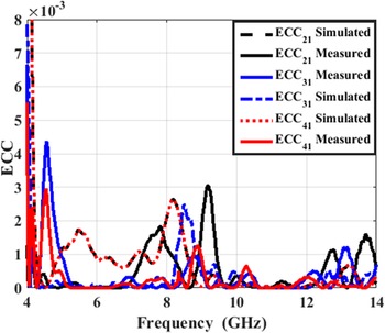
The envelope correlation coefficient (ECC), diversity gain (DG), and channel capacity loss (CCL) are the three main important parameters used to check the quality and diversity of the MIMO systems. The three parameters can be extracted and calculated from the simulated and tested S-parameters and also from the far-field outcomes. When these MIMO parameters have acceptable limits that are mean, the suggested antenna can be used in the desired application. The linking between ports can be determined by the ECC MIMO parameter. The lower value of ECC produces higher MIMO performance. The acceptable limits of the ECC are lower than 0.5 and it can be extracted and calculated from equation (1) [Reference Peng, Zhi, Yang, Cai, Wan and Liu26,Reference Ibrahim and Ali27].

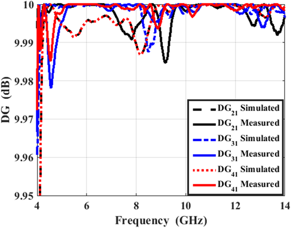
The measured and simulated ECC results of the MIMO antenna at ports 1 between ports 1, 2, ports 1,3, and ports 1,4 are displayed in Fig. 13. The ECC values for the simulated and tested results are lower than 0.005 within the working frequency bands with a good tendency between the two results. The extracted value of the ECC is lower than the acceptable limits which confirm the higher isolation between ports which leads to higher MIMO performance.The DG is linked to the ECC and its value can be taken from equation (2) [Reference Rosengren and Kildal28]

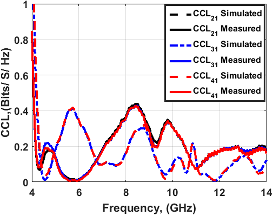
Figure 14 illustrates the measured and simulated DG results of the MIMO antenna at port 1 between ports 1, 2, ports 1,3, and ports 1,4. The DG values for the simulated and tested results are around 9.98 dB within the working frequency bands with a good tendency between the two results.The CCL (bit/s/Hz) is the third parameter that evaluates the transmitted data rates over the channel and its value can be calculated from equations (3), (4), and (5) [Reference Shin and Lee29,Reference Ibrahim, Ahmed and Ahmed30].


ECC results of the suggested 4 ports UWB slot antenna at port 1.

DG results of the suggested 4 ports UWB slot antenna at port1.

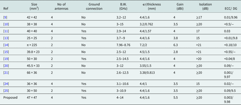
The measured and simulated CCL results of the MIMO antenna at port 1 between ports 1, 2, ports 1,3, and ports 1,4 are illustrated in Fig. 15. The CCL values for the simulated and tested results are ≤0.4 bit/s/Hz (the acceptable limits) within the working frequency bands with a good tendency between the two results. Finally, the suggested antenna is compared with the other designs from the literature to confirm the proposed design's novelty and application as tabulated in Table 1. The suggested antenna permits an increased number of ports with the connected ground and miniaturized size. Also, the antenna has high isolation with suitable gain which suggests our antenna to be utilized in the UWB systems.
CCL results of the suggested 4 ports UWB slot antenna at port 1.

Comparison between the suggested MIMO antenna and the other selected designs.

Conclusion
A compact size 4 ports MIMO slot antenna with low mutual coupling, wide bandwidth, suitable radiation pattern features, low ECC, high DG, and low CCL has been discussed and validated successfully. The high isolation has been accomplished without placing any extra structures. This is because of the antenna orientation in orthogonal configuration. The antenna was operated from 4–14 GHz with isolation greater than 20 dB between ports. As well as, the antenna has achieved high diversity realization which guarantees high MIMO realization. The good results of the suggested antenna qualify it to be appropriate for UWB and X-band MIMO systems.
Author contributions
All authors contributed equally to analyzing data and reaching conclusions, and in writing the paper.
Financial support
There is no funds, grants, or other support was received to conduit this study.
Conflict of interest
The authors report no conflict of interest.
Data availability statement
There are no supplementary materials, and the data is available upon reasonable request.
 Ahmed A. Ibrahim (M'19, SM'20) was born in 1986. He received the B.Sc. degree, and M.Sc., Ph.D. in Electrical Engineering from the Electronic and Communication Engineering Department, Minia University, El-Mina, Egypt in 2007, 2011, and 2014 respectively. He is now an associated professor in the electrical engineering department in the faculty of engineering Minia University. He has been a visiting professor at University Pierre and Marie Curie, Sorbonne University, Paris VI, France for 7 months and Otto-von-Guericke-Universität Magdeburg-Germany for 6 months. He has published more than 95 peer-reviewed journals and conference papers. His research has focused on miniaturized multiband antennas/wideband, microwave/millimeter components, DRA metamaterial antenna, graphene antenna, and microwave filters. Also, his research includes MIMO antennas and energy harvesting systems. Dr. Ahmed A Ibrahim is a senior member of the IEEE and a senior member in URSI also a member of the national committee of radio science in Egypt. He is currently a reviewer in, IEEE Antennas and Wireless Propagation Letters, IEEE Microwave Wireless Components, IEEE access, IET Microwave, Antenna and Propagation, IET Electronics Letters, MOTL, Analog Integrated Circuits, and Signal Processing, and many other journals and conferences. In 2020, and 2021 he was named in the top 2% of scientists in ‘A standardized citation metrics author database annotated for scientific field/‘Updated science-wide author databases of standardized citation indicators’.
 Amira Eltokhy received the M.S. degree in wireless mobile communication systems and the Ph.D. degree in microwave engineering from the University of Greenwich, London, U.K., in 2015 and 2019, respectively. She was a post-doctoral associate with Bangor University, Bangor, U.K., from 2019 to 2020. Afterwards, she worked as a lecturer at MSA, Egypt from 2020–2021. In addition to that, she started a company in MedTech since 2019. Currently, she is the CEO of Rapid Biolabs. Her research interests include microwave systems and biomedical engineering in addition to artificial intelligence integration in both fields.
 Ahmed Fawzy Daw is a Ph.D. holder and researcher in Radiofrequency and Microwave field; he is a member of European Microwave Association and Senior Member IEEE. His researchers are focused on the microwave circuits, RF metamaterial designs, RF MEMS and its applications. He has more than 17 international publications in conferences and journals, and reviewer in many international journals. He is Assistant professor in electronics and communications department, and director of training and development unit from 2017.