

I. INTRODUCTION
Aluminum nitride (AlN) piezoelectric thin film is very popular in RF micro-machined resonators and filters MEMS devices. The advantages arise from its high resistivity and piezoelectric coefficient, which is the largest among nitrides, as well as the possibility of being deposited at temperatures as low as 500°C and patterned using conventional photolithographic techniques. AlN generally exhibits smaller piezoelectric and dielectric constants and differs from PZT materials in that it is polar rather than ferroelectric.
Theoretical results have indicated that nitride semiconductors possess a large spontaneous polarization [Reference Bernardini, Fiorentini and Vanderbilt1], associated with which are electrostatic charge densities analogous to those produced by piezoelectric polarization fields. In wurtzite structure the polar axis is parallel to the c-direction of the crystal lattice, which may give rise to a macroscopic spontaneous polarization that can reach values up to 0.1 C/m2. This macroscopic lattice polarization is equivalent to two-dimensional fixed lattice charge densities with values between 1013 and 1014 e/cm2 located at the two surfaces of a sample [Reference Zoroddu, Bernardini, Ruggerone and Fiorentini2, Reference Ambacher3].
In inhomogeneous alloy layers, variations in composition are expected to create non-vanishing and spatially varying spontaneous and piezoelectric polarization fields and associated charge densities that can significantly influence the material properties. Thus in contrast to the single crystalline material, the sputtered one exhibits near-zero, positive or even negative piezoelectric response, indicating a change in crystalline orientation, grain size, concentration of defects or even a complete reversal of dipole orientation [Reference Ruffner, Clem, Tuttle, Dimos and Gonzales4, Reference Stutzmann5]. A typical example of the dependence of the piezoelectric response on the sputtering power increase, obtained from data reported in refs. [Reference Kamohara, Akiyama and Kuwano6] and [Reference Akiyama7], is presented in Fig. 1.
Dependence of AlN piezoelectric response films on sputtering power. The films were grown on different substrates. The dashed line is drawn to show the trend.

The presence of spontaneous polarization makes AlN an attractive candidate for dielectric layers in capacitive Radio Frequency – Micro-Electro-Mechanical Systems (RF-MEMS) switches, since the spontaneous polarization may be used to diminish or control the dielectric charging effects.
Recently, AlN has been introduced in MEMS switches [Reference Setter8, Reference Lisec, Huth and Wagner9] and reliability tests have proved that under low pull-in bias or certain polarity the device degradation may be extremely low. This behavior cannot be explained in terms of the usual treatment of dielectric charging, which constitutes the major failure mechanism of capacitive RF-MEMS switches. On the other hand, although there is no direct evidence on how the piezoelectric properties may affect the charging process and thus prolong the device lifetime, experiments based on both metal-insulator-metal (MIM) capacitors and MEMS switches have indicated the presence of a spontaneous polarization, attributed to dislocations, which were considered as responsible for the controllable dielectric charging [Reference Papaioannou and Lisec10].
The aim of the present work is to investigate the electrical properties of AlN crystalline films and attempt to provide information on the effect of material spontaneous polarization and its effect on the dielectric charging. The investigation will include experimental data obtained from the characterization of MIM capacitors as well as the effect of electric field on dielectric charging in MEMS switches operating below pull-in voltage.
II. BASIC CONSIDERATIONS
It is well known that the performance and reliability of an RF-MEMS capacitive switch are determined by the charging properties of the insulating film, which is deposited under the moving electrode (Fig. 2). Parameters such as the pull-in and pull-out voltages as well as the bias for capacitance minimum depend directly on the dielectric film surface charge, i.e. macroscopic polarization [Reference Papaioannou and Lisec10, Reference Rottenberg, Nauwelaers, De Raedt and Tilmans11–Reference Rottenberg, De Wolf, Nauwelaers, De Raedt and Tilmans14].
Simplified geometry of a capacitive MEMS switch.

In the case of crystalline AlN macroscopic polarization will arise from the superposition of the piezoelectric effect, when the dielectric film is under stress, and from material spontaneous polarization. The piezoelectric effect of AlN thin films deposited using reactive RF sputtering depends strongly on the composition of the underlying electrode layer [Reference Ruffner, Clem, Tuttle, Dimos and Gonzales4]. Depending on substrate composition, AlN deposition may result in a piezoelectric response in the negative or positive sense. Given that the AlN crystallites are oriented in the c-axis direction, normal to the substrates, the near-zero piezoelectric response in AlN films may suggest a nearly equal mixture of the two dipole orientations. In the case of a Pt bottom electrode, it has been reported that the AlN films indicate c-axis orientation [Reference Akiyama, Nagao, Ueno, Tateyama and Yamada15] with high crystallinity, which arises from the fact that the crystallinity of the Pt electrode is high, the surface roughness is low and the Pt (111) planes match well with the hexagonal AlN structure. Regarding spontaneous polarization, although there were some experimental data, which can be compared with the predicted piezoelectric constants, so far the experimental values of the spontaneous polarization of III-V nitrides are still unknown [Reference Yan16].
Recently, Yan et al. [Reference Yan17] calculated the temperature dependence of the pyroelectric coefficient as well as the spontaneous polarization of AlN, over a wide temperature range from 0 to 1000 K, using the Debye model and existing experimental data of the pyroelectric coefficient of AlN. In their paper they reported that the spontaneous polarization changes a little from 0 to 1000 K.
The polarization processes of a dielectric are usually studied with the aid of the thermally stimulated depolarization currents method [Reference Vandershueren, Casiot and Braunlich18, Reference van Turnhout and Sessler19]. The common practice is to charge the sample isothermally at a sufficiently high temperature before it is subjected to thermally stimulated depolarization. However, the sample can be charged while being heated linearly. Such a thermally stimulated polarization process has several advantages. One of these is that the measured thermally stimulated polarization current (TSPC) reveals how the orientation of dipoles is proceeding. A second advantage is that the search for optimum polarizing temperature is eliminated (hence the overheating of specimens is avoided) and finally the TSP current measurement reveals the temperature at which ohmic conduction becomes significant. In polar materials, such as AlN, this procedure is essential since it reveals both the dipoles orientation. The study of temperature allows the determination of characteristic parameters such as the characteristic time constant and its activation energy, which allows the estimation of the charging process of MEMS switches at room temperature.
In the TSPC method, charging is carried out in the presence of an electric field. The density of the current generated by the polarization build-up and material conductance is given by

where P is the average dipole moment per unit volume. Following procedures that have been described in detail elsewhere [Reference Vandershueren, Casiot and Braunlich18, Reference van Turnhout and Sessler19], Equation (1) leads to

where q is the heating rate, τ 0 the polarization process time at infinite temperature and E A the activation energy of the polarization process.
In the case of a piezoelectric and pyroelectric material such as AlN, the thermally stimulated polarization current will include contributions from all piezoelectric and pyroelectric processes [Reference Vandershueren, Casiot and Braunlich18–Reference Fedosov and von Seggem21]. Finally, when the conductivity of the dielectric film is temperature dependent and for which we usually assume an Arrhenius type of temperature dependence, g(T) = g 0 exp (U/kT) with U the activation energy, the thermally stimulated polarization current will be given by

III. EXPERIMENTAL ANALYSIS
MIM capacitors were fabricated by depositing AlN on a Ta/Pt/Au/Pt stack. The sputtering deposition process was adopted for the dielectric film. Deposition was performed at Uniaxis Liechteinstein. The top electrode was again Ta/Pt/Au/Pt with a smaller diameter to avoid excess leakage at the MIM edges. The dielectric film was N face with a thickness of 200 nm and a breakdown voltage larger than 40 V. The TSPC spectrum was obtained by applying a constant bias, which was low enough so as to imply a low ohmic current and give rise to a well-resolved polarization current. The temperature was ramped with a constant rate of 2.5 K/min in the range of 300–450 K. The current was measured with a Keithley 6487 pico-ampermeter, which also provided the required bias of ±0.5 V.
The capacitance of air-bridge-type RF-MEMS switches was monitored with a Boonton 72B capacitance meter. The switches were fabricated with a standard lithographic process on high-resistivity silicon wafers.
Finally, the capacitance–voltage characteristics were recorded in the temperature range of 300–450 K at a step of 5 K.
IV. RESULTS AND DISCUSSION
A) MIM capacitors
As already mentioned, theoretical calculations on the temperature dependence of spontaneous polarization have shown that it varies a little with temperature. On the other hand, the same calculations have shown that the pyroelectric coefficient varies proportionally to T 3 up to around 400 K. The pyroelectric coefficient is calculated using the relationship [22]
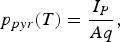
where I P is the pyroelectric current and A the sample area.
In order to determine the interference from spontaneous polarization and pyroelectric effect, we measured the TSPC current under no bias (Fig. 3). The TSPC current showed that it is proportional to T 3 (dashed line) as predicted by Yan et al. [Reference Yan17].
TSPC current under no bias. The dashed line is the fitted curve proportional to T3.

Furthermore, the temperature dependences of TSP currents obtained from a MIM capacitor and for opposite bias polarities are presented in the inset of Fig. 1a. Here it must be pointed out that the bias polarities were measured on the top dielectric surface with respect to the bottom one. The plots clearly show the presence of thermally activated conductivity and the practical absence of any polarization process when the top electrode is negative. In contrast, when the top electrode is positive a polarization process is present. The agreement with Equation (3) is shown in Fig. 4, where in the high-temperature range (T > 370 K) and for both polarities the material conductivity dominates, thus masking any possible TSPC contribution, and reveals an activation energy (U) of about 0.6 eV. This activation energy lies close to that of the N or Al vacancy, both of which are reported to have activation energies of 0.5 eV [22].
TSPC current dependence on temperature.

Fig. 5 presents the difference of TSPC currents. Equation (2) was used further to fit the experimental data of Fig. 5 and the fitting results showed excellent agreement with the applied model. In order to interpret the results, we must take into account the following: (i) the contribution from the pyroelectric effect is small in the temperature region of the peak; (ii) the contribution of spontaneous polarization is practically negligible as stated in [Reference Yan17]; (iii) the fact that the peak is present under certain polarity must exclude the dipolar and space charge polarization since the former leads to symmetrical TSPC spectra and the latter to almost symmetrical spectra.
TSPC difference and fitting results using Equation (2).

Therefore, the difference in TSPC spectra has to be attributed to a change in the AlN. Presently, the available data do not allow one to draw a conclusion on the origin of change of polarization. Taking further into account that the temperature increases with a constant rate of 2.5 K/min, we calculated the change of polarization, ΔP = 5 × 10⁻⁷ C/cm2. Further bearing in mind that the AlN spontaneous polarization is about 0.09 C/m2 (9 μC/cm2) [Reference Ruffner, Clem, Tuttle, Dimos and Gonzales4], we are led to the conclusion that the calculated difference constitutes a negligible change in spontaneous polarization, and according to the available literature it has to be attributed to defects connected to dislocation or other structural or point defects in polycrystalline AlN [Reference Ambacher3, Reference Vergara, Olivares, Iborra, Clement, Sanz-Hervás and Sangrador23, Reference Westwood and Notis24].
B) MEMS switches
The capacitance–voltage characteristic of a MEMS switch with AlN dielectric is presented in Fig. 6. The bias is applied to the coplanar waveguide line with respect to the ground plane, the bridge. So negative bias values correspond to a positive charge at the top surface of the dielectric layer. A close inspection of the below pull-in characteristic and specifically in the negative bias region reveals a step-like behavior, which may be attributed to the presence of a charge that is removed when electric fields greater than 3 × 10⁴ V/cm are applied. The calculation has been performed assuming a sacrificial layer of about 2.5 μm and the capacitor area is about 2.3 × 10⁻⁴ cm2. The result shows that this value is comparable to the one applied for TSPC assessment of MIM capacitors. This conclusion is drawn from Equation (5), where in the absence of P TSPC the capacitance is lower. Moreover, the fact that the polarization is performed contact-less [Reference Papaioannou, Wang, Bessas and Papapolymerou25] supports the hypothesis of AlN bulk polarization.

where P(V) is the electric field-induced polarization, including both the instantaneous and time-dependent ones, z 1 the AlN film thickness, z 2 the distance between the bridge and the CPE line, and P TSPC the polarization determined from TSPC assessment. Now, if we assume that the suspended electrode displacement d is small enough, we can estimate the change of the P TSPC component from

Capacitance–voltage characteristic of a MEMS switch with AlN dielectric.

Taking into account the device dimension, we found that |ΔP TSPC| ≈ 8.3 × 10⁻⁷ C cm−2, which is in excellent agreement with the value obtained from TSPC data. Here it must be emphasized that the fact that practically the same results were obtained with injecting, MIM capacitor, and non-injecting, MEMS switch in up-state, electrodes leads us to the conclusion that the “dielectric charging” in crystalline AlN, with normal to CPW line c-axis orientation, is a bulk phenomenon and not a surface one. In all cases it is not related to surface charges, which may be compensated by charge injection. It is evident that the present experimental results are not sufficient to allow us to draw any conclusions that would give a clearer image on this effect, and further investigation is in progress.
V. CONCLUSION
Dielectric charging has been investigated in MEMS switches with AlN dielectric film. The investigation was performed by using MIM capacitors and MEMS capacitive switches. The TSPC assessment showed that the pyroelectric effect plays a minor role in dielectric charging and that there is a bulk polarization mechanism that seems to be removed under electric fields exceeding magnitudes of about 3 × 10⁴ V/cm. The same effect is observed when the temperature is increased beyond 360 K (87°C). The polarization step corresponds to an equivalent surface charge density change of about 6.6 × 10⁻⁷ C/cm2, a charge density that is much smaller than the theoretically predicted spontaneous polarization. Finally, the change in polarization has to be attributed to defects connected to dislocation or other structural or point defects in polycrystalline AlN.
ACKNOWLEDGEMENT
The authors wish to acknowledge that the present work has been partially supported by the EU-funded NoE project AMICOM (No. 50735-21-11-03).
 Papandreou Eleni received a B.Sc. degree in physics from University of Athens in 2005 and an M.Sc. degree in microelectronics from University of Athens in 2007. Presently, she is working as a research assistant with the Microelectronics Group at the Solid State Physics Section of Physics Department at University of Athens. Her interests are focused on the reliability of MEMS capacitive switches. Miss E. Papandreou has published two papers and contributed 10 conference presentations on the dielectric charging in MEMS capacitive switches.
 Papaioannou George received a B.Sc. degree in physics from University of Athens, an M.Sc. degree from University College London, England, and a Ph.D. degree in solid state physics from University of Athens. In 1975 he joined the Physics Laboratory, Physics Department of University of Athens, as a research assistant and later (1978) as a lecturer conducting research in III–V compound semiconductors, mainly in semi-insulating GaAs. In 1982 he joined the Solid State Physics Section at University of Athens, where from 1982 he worked as a senior lecturer. Presently he is an associate professor at the Solid State Physics Section of Athens University, leading a team on the transport properties and the radiation effects in compound semiconductors and III–V semiconductor devices and the interaction of light in III–V compound semiconductors and SOI structures and devices. Recently, he is working on the investigation of polarization effects in insulating materials in RF-MEMS switches. He has contributed to 70 publications and more than 130 conference presentations.
Thomas Lisec studied at the Lomonossow Institute for Precise Chemical Technology in Moscow, Russia, and received his M.Sc. degree in 1988. From 1988 till 1991 he worked as a process engineer in the DRAM facility of the Center of Microelectronics in Dresden, Eastern Germany. Since 1991 he is a research scientist with the Fraunhofer Institute for Silicon Technology ISiT. In 2000 he received a Ph.D. degree from the University in Kiel in materials engineering. He has worked on a wide variety of MEMS, for example surface-micromachined pressure sensors, micropumps and microvalves, MEMS-based pipetting systems and several types of physical and chemical sensors. Currently, his main research interests are the fabrication and wafer-level packaging of RF-MEMS.



